Int. J. Electrochem. Sci., 11 (2016) 1370 - 1381
International Journal of
ELECTROCHEMICAL
SCIENCE
www.electrochemsci.org
Short Communication
Study of Silicon Composite for Negative Electrode of
Lithium-Ion Battery
T.L.Kulova1,*, A.A.Mironenko2,3, A.M.Skundin1, A.S.Rudy2,3, V.V.Naumov2, D.E.Pukhov3
1
Frumkin Institute of Physical Chemistry and Electrochemistry, 31-4 Leninskii prosp., 119071 Moscow, Russia
2
Yaroslavl Branch of the Institute of Physics and Technology, 21 Universitetskaya ul., 150007 Yaroslavl, Russia
3
Demidov Yaroslavl State University, 10, Sovetskaya ul., 150000 Yaroslavl, Russia
*
E-mail: [email protected]
Received: 10 November 2015 / Accepted: 30 November 2015 / Published: 1 January 2016
Using of layered silicon-based composites instead of thick-film silicon electrodes is an effective way for improvement of their cycling stability. In the present work, the transformation of electrode with layered Si-O-Al composite at cycling is studied. Fresh prepared electrodes have columnar morphology with average pillars’ diameter of 50 nm and inter-pillar distance 1–2 nm. After 100 cycles, the columnar morphology remains as a whole, but total thickness of layered composites increases by 7–10-fold. This phenomenon is likely to be caused by both structure changes and SEI formation.
Keywords: lithium-ion battery, Si-O-Al composite, anode, irreversible capacity, transformation
1. INTRODUCTION
Int. J. Electrochem. Sci., Vol. 11, 2016
1371 amorphous silicon leads to fast degradation during the cycling, which is caused by destruction and partly flaking of films from substrate. Film stability during the cycling can be enhanced using the composite materials among which the popular are the composites of silicon with carbon. There are many publications dedicated to such composites and the reviews on them one can find in [1, 12 and 13]. Among the composite electrodes the particular interest is devoted to electrodes, whose active part consists of plurality of very thin layers of silicon and another material. Layered electrodes made from silicon and carbon composites are described in [14–16], electrodes from silicon and silver composites are described in [17, 18], silicon and germanium ones in [19], silicon and iron ones in [20] and even just porous and nonporous silicon in [21]. In our previous work [22], thin film electrodes with alternated layers of silicon and oxidized silicon whose constitution is noted as SiOx were investigated.
There are notifications in literature that thin film electrodes made of silicon-aluminum alloy reveal high stability during the cycling and this fact was partly explained by higher conductivity of such films in comparison with pure silicon. [23–28].
In this paper, we report on experimental study of electrochemical properties of electrodes with thin-layer Si–O–Al structure, made by magnetron sputteringtechnique, and the study of transformation of such electrodes during the cycling process.
2. EXPERIMENTAL METHODS AND MATERIALS
Electrodes were manufactured by magnetron sputtering by using “Oratoria 22” instrument. The titanium foil with thickness 15 μm was used as a substrate. Before the sputtering this foil was treated by H2SO4:HF:H2O (1:1:20) mixture for 30 s at room temperature. Si–O–Al composite film was
deposited by using simultaneously silicon and aluminum targets. Before the sputtering process, the substrate was heated to 140 °C, whereas the temperature of sputtering was 70 °C with no further forced heating of substrate. The residual gases pressure was 2.5 10-5 Torr. Argon and oxygen were used as a working gases. During the sputtering, the consumption of oxygen was 8 cm3 min-1 at 4.8∙10-5 Torr pressure. Total oxygen and argon pressure was 2∙10-3
Torr. The power of magnetron discharge maintained at 420–480 W for silicon target and 200–210 W for aluminum target. We produced electrodes with silicon composite in the form of four-layer structure where the first and the third layers (counting from substrate) were enriched with aluminum and the second and the fourth layers contained less aluminum. For lacking of aluminum, we turned off the aluminum target. As a witness for defining of composure, thickness, morphology of surface and cleavage of silicon containing films we used the silicon wafers.
Wherein the INCAx-act analyzed the narrow band by fracture cross-section from silicon substrate to film surface. Such a technique gave us opportunity of qualitative distribution of elements by film thickness. This method cannot give the precise quantitative composition in each point because of quite large spot during the scanning and this fact distorts the composition map and doesn’t allow to resolute layers less then 100–200 nm.
Electrochemical measurements at Si-O-Al-electrodes were carried out in sealed three-electrode cells of flat-parallel construction. Cells contained one working electrode, two lithium counter and one lithium reference ones. We used 1М LiPF6 in ethylene carbonate - diethylcarbonate -
dimethylcarbonate (1:1:1) mixture as an electrolyte. The cells were assembled in glove box with humidity about 10 ppm. We used non-woven polypropylene separator. The electrolyte humidity was less than 20 ppm. Cycling of electrochemical cells was performed with computerized cycler of Buster Co. (St. Petersburg, Russia). Potential limits of cycling were 0.01–2.0 V relatively to lithium reference electrode. After cycling the cells were disassembled and working electrodes were thoroughly rinsed by dimethoxyethane in a glove box.
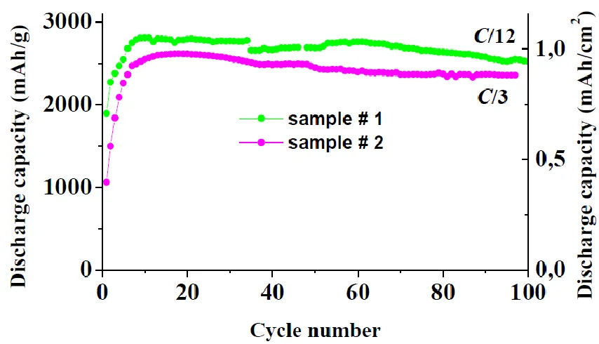
This work provides the results of cycling of two identical samples. Sample #1 was tested at 270 mA/g (0.11 mA/cm2), that corresponded to С/12 mode. Sample #2 was tested at 1080 mA/g (0.44 mA/cm2) that corresponded to С/3 mode. (So-called С- mode or C-rate expressed in mA/g is known to be numerically a fraction or multiple of the rated capacity expressed in mAh/g). The calculated theoretical capacity of Al composite was equal 3240 mAh/g. The value of average load of Si-O-Al composite was 0.41 mg/cm2 taking composite density of 2.1 g/cm3 into account.
3. RESULTS AND DISCUSSION
3.1. Physico-chemical characteristics of original Si-O-Al composite films
The views of fracture cross-sections of original Si-O-Al films are presented in Figure 1. The electron microscopy data show that the thickness of silicon-containing composite was 2036 nm. Dark bands at cross-section correspond to amorphous silicon while light bands correspond to aluminum-enriched silicon (Figure 1a). At higher magnification, one can see (Figure 1b) columnar morphology of Si-O-Al composite, i.e. such composite looks like a porous film, which consists of vertical pillars 30– 50 nm in diameter. On Figure 1c the top view of Si-O-Al composite is presented. At 100 kx magnification the globules of 50–100 nm size which were formed by small particles of 10–20 nm size are clearly seen.
Int. J. Electrochem. Sci., Vol. 11, 2016
1373
[image:4.596.109.489.64.687.2]
Table 1. Chemical composition of original Si-O-Al composite film.
Element Wt. % Wt. % Rel. error
Atomic %
C 3.02 0.34 6.44
O 6.91 0.14 11.08
Al 7.21 0.05 6.86
Si 82.63 0.32 75.51
Fe 0.24 0.03 0.11
Total 100.00 100.00
3.2. Electrochemical properties of Si-O-Al electrodes
The discharge capacity evolution at galvanostatic cycling of Si-O-Al electrodes with different current loads (С/12 for sample #1 and С/3 for sample #2) is shown in Figure 2. As it is seen both modes show discharge capacity growth at the beginning (first 8–10 cycles). Then at C/12 and C/3 modes one can observe stable cycling for no less than 100 cycles. Theoretical capacity of Si-O-Al composite is calculated 3240 mAh/g. So discharge capacity obtained in the experiment is close to the theoretical value.
[image:5.596.96.523.437.682.2]Int. J. Electrochem. Sci., Vol. 11, 2016
1375
Figure 3. Charge-discharge curves of Si-O-Al-electrodes during the cycling. The curves are corresponded to 20th cycles. Sample #1 was tested at 270 mA/g (0.11 mA/cm2), that corresponded to С/12 mode. Sample #2 was tested at 1080 mA/g (0.44 mA/cm2), that corresponded to С/3 mode.
Increasing of capacity at first several cycles could be related to partial reduction of excess amounts of oxygen, which is contained in Si-O-Al composites, additive amorphosizing of this composite, and diminishing of resistance. However, in some cases the same event took place in pure silicon electrode investigation [7, 29–34]. In article [30] such growth in discharge capacity was explained as probable recrystallization of silicon. It should be pointed out that quantitatively such capacity growth at initial cycles varies a lot from paper to paper.
The discharge capacity lost from 10th to 100nd cycles doesn’t exceed 0.11% and 0.12 % per cycle for sample #1 and sample #2, respectively.
Charge-discharge curves of sample #1 and sample #2 at 20th cycles are shown on Figure 3. As one can see, the shape of such curves is almost the same during the cycling. The differences between average potentials at insertion and extraction of lithium (ΔЕ) for 20th
cycles of sample #1 and sample #2 are 0.270 and 0.266 V, respectively.
3.3. Physico-chemical characteristics of original Si-O-Al composite films after cycling
[image:6.596.86.497.81.332.2]
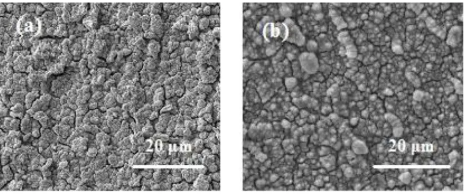
formation of SEI layer, the original Si-O-Al smooth surface disappears. Instead, the Si-O-Al composite film presents a rough and porous morphology. Cracking of the Si-O-Al film is regarded as the main cause of the capacity decrease.
Figure 4. Morphology of surface of sample #1 and sample #2 after 100 cycles
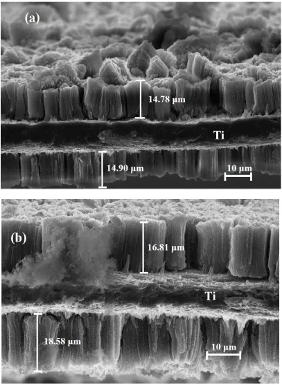
The SEM images of fracture cross-sections of sample #1 and sample #2 are presented at Figure 5. As one can see the thickness of Si-O-Al composite during the cycling strongly increase up to 14.78– 14.90 μm for sample #1, and up to 16.81–18.58 μm for sample #2. In other words at the surface of titanium foil the layers with thickness by 7–10 times more than that of the original Si-O-Al composite is appeared.
It is suggested that that the good cycling performance of Si-O-Al composite should be attributed to the maintenance of electric contact between the Si-O-Al layer and the current collector during cycling. This proves the advantage columnar morphology of Si-O-Al composite, i.e. such composite looks like a porous film, which consists of vertical pillars 30–50 nm in diameter. After 100 cycles, the columnar morphology remains as a whole, but total thickness of layered composites increases by 7–10-fold.
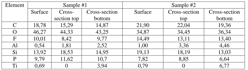
The elemental composition of the samples after cycling was investigated in three points: at surface, in the upper part of fracture cross-section and in the lower part of fracture cross-section. The results are presented in Tables 2.
[image:7.596.79.537.147.340.2]Int. J. Electrochem. Sci., Vol. 11, 2016
[image:8.596.95.502.68.623.2]1377
Figure 5. Fracture cross-sections of sample #1 (a) and sample #2 (b) after 100 cycles
If atomic ratio F:P in studied samples was 1:6 one could suggest that unwashed electrolyte salt (LiPF6) remains at the surface or in the pores of composite film. However Table 2 shows that F:P ratio
[image:9.596.39.561.214.362.2]
Irreversible capacity of sample #1 at first cycle amounted to 14.6 % of reversible capacity, and at all following cycles it was from 1.5 to 1.7 %. Total irreversible capacity for 100 cycles for sample #1 amounted to 3.5 mAh. Total irreversible capacity of sample #2 at first cycle was 14.9 % of reversible capacity and varied from 0.7 to 1.0 % for the following cycles. Total irreversible capacity for 100 cycles for sample #2 was about 2.75 mAh. Data on irreversible capacity agree with increase in fluorine, phosphorus, oxygen and carbon contents for both electrodes.
Table 2. Elemental composition (wt.%) of sample #1and sample #2 after 100 charge-discharge cycles.
Element Sample #1 Sample #2
Surface Cross-section top
Cross-section bottom
Surface Cross-section top
Cross-section bottom
C 18,78 15,29 14,87 21,90 22,04 19,36
O 46,27 44,33 43,25 34,87 34,45 36,34
F 10,01 8,42 9,77 14,49 13,11 13,40
Al 0,54 1,81 2,52 1,00 3,36 4,46
Si 13,92 18,53 14,95 19,13 18,19 13,03
P 9,79 11,62 10,7 7,82 8,85 6,64
Ti 0,69 0 3,94 0,79 0 6,77
Publications devoted to the study of electrolyte reduction at silicon electrodes are few and far between [35–38] in contrast with those at carbon electrodes. Undoubtedly, these processes are very complicated since both aprotic solvent and salt anion can undergo the reduction. During reduction of the electrolyte containing ethylene carbonate, some metastable linear alkylcarbonates (−Si−OCH2CH2OCO2Li, −Si−CH2CH2OCO2Li, R(OCO2Li)2) appear [35]. These alkylcarbonates can
comprise the polymeric component of SEI, but also can interact with the traces of water and hydrogen fluoride (see e.g. [36]):
(CH2OCO2Li)2 + H2O → Li2CO3 + CO2 + (CH2OH)2 ,
ROCO2Li + HF → LiF + ROCO2H.
During the reduction of PF6- anion or products of its conversions like POF3 or PF5, compounds
with stoichiometry F:P = 1:3 form:
POF3 + 2Li+ + 2e− → LiF + LiPOF2,
PF5 + 2Li+ + 2e− → 2LiF + PF3,
PF3 + 2Li+ + e− → LiPF2 + LiF.
(The presence of PF-containing species in SEI is documented also in [38]). Such processes and similar reactions explain obtained data of F:P ratio in SEI.
The authors of [39] believe that SEI formation is the only (or at least, the main) reason of thickness increase of Si-film electrodes. The results of present study show that changes of size of silicon pillars per se play not less role during cycling. Similar conclusions could be found also in [40-42].
Int. J. Electrochem. Sci., Vol. 11, 2016
1379 number of papers report about several hundreds of cycles for silicon films with thickness less than 200 nm. In this connection very demonstrative is [43], which presents data about 400 cycles for Si-electrodes with thickness from 100 to 520 nm, 200 cycles for 1000 nm, and only 50 cycles for 3.6 μm. Thus, the present work is the first evidence of enormous thickening of silicon films in the course of prolonged cycling.
4. CONCLUSIONS
We prepared layered Si-O-Al composites by alternate magnetron sputtering pure silicon and mixture of silicon and aluminum in oxygen-containing environment onto titanium foil. The composite thickness was more than 2 μm. Such composites were found to have columnar morphology with average pillars’ diameter of 50 nm, and inter-pillar distance 1–2 nm. Discharge capacity obtained in the experiment was close to the theoretical value and was equal to 2800 mAh/g. During the multiple cycles of lithium insertion-extraction the composite thickness increases. Thickness growth happens unequally along the electrode surface. The elemental composition of Si-O-Al films changes during the cycling, specifically, fluorine and phosphorous appear at the surface and in the bulk of the composite. Simultaneously oxygen and carbon contents increase. This suggests the formation of passive film on the pillars’ surface, due to electrolyte reduction. Irregularity of thickness growth of Si-O-Al can be a consequence of non-uniform current density distribution, which can be related with different resistance in different areas.
ACKNOWLEDGEMENTS
The authors would like to acknowledge the financial support from the Ministry of Education and Science of the Russian Federation (the Agreement No. 14.604.21.0126 of August 26, 2014. Unique identifier of applied scientific researches is RFMEFI60414X0126).
References
1. R.A. Sharma and R.N. Seefurth, J. Electrochem. Soc., 123 (1976) 1763. 2. R.A. Huggins, Solid State Ionics, 113–115 (1998) 57.
3. H. Li, X. Huang, L. Chen, Z. Wu, Y. Liang, Electrochem. Solid State Lett., 2 (1999) 547. 4. S. Bourderau, T. Brousse, D.M. Schleich, J. Power Sources, 81–82 (1999) 233.
5. S.-J. Lee, J.-K. Lee, S.-H. Chung, H.-Y. Lee, S.-M. Lee, H.-K. Baik, J. Power Sources, 97–98 (2001) 191.
6. A. Netz, R.A. Huggins, W. Weppner, J. Power Sources, 119–121 (2003) 95.
7. S. Ohara, J. Suzuki, K. Sekine, T. Takamura, J. Power Sources, 119–121 (2003) 591. 8. T. Takamura, S. Ohara, M. Uehara, J. Suzuki, K. Sekine, J. Power Sources, 129 (2004) 96. 9. K.-L. Lee, J.-Y. Jung, S.-W. Lee, H.-S. Moon, J.-W. Park, J. Power Sources, 129 (2004) 270. 10. S. Ohara, J. Suzuki, K. Sekine, T. Takamura, J. Power Sources, 136 (2004) 303.
11. Ye. Zhang, Z.-W. Fu, Q.-Z. Qin, Electrochem. Comm., 6 (2004) 484.
14. Yu.E. Roginskaya, T.L. Kulova, A.M. Skundin, M.A. Bruk, A.V. Klochikhina, N.V. Kozlova, V.A. Kal’nov, and B.A. Loginov, Russian Journal of Physical Chemistry A, 82 (2008) 1655. 15. Yu.E.Roginskaya, T.L.Kulova, A.M.Skundin, M.A.Bruk, E.N.Zhikharev, V.A.Kal’nov, and
V.B.Loginov, Russian Journal of Electrochemistry, 44 (2008) 1197.
16. Wei Li, Rong Yang, Xiaojuan Wang, Teng Wang, Jie Zheng, Xingguo Li, J. Power Sources, 221 (2013) 242.
17. Pat. 6 828 063 US, Int. Cl. H01M4/02 (20060101); H01M 4/66 (20060101); H01M 4/62
(20060101); H01M 4/38 (20060101); H01M 10/36 (20060101); H01M10/40 (20060101); H01M 4/40 (20060101); H05K 1/16 (20060101); H01M 004/40; H01M 004/38. Anode thin film for lithium secondary battery / Park Y.-S., Baik H.-K., Lee S.-M., Oh J.-Y.; 09/987,939, filed 16.11.2001, date of patent 07.12.2004–4 p. 2 drawings.
18. Pat. 7 316 867 US, Int. Cl. H01M 4/58 (20060101); C23C 14/00 (20060101); C23C /14/32 (20060101); H01M10/32 (20060101); H01M 4/34 (20060101); H01M 4/54 (20060101) Method for manufacturing a multi-layered thin film for use as an anode in a lithium secondary battery / Park Y.-S., Oh J.-Y., Baik H.-K, Lee S.-M.; 10/997.882, filed 29.11.2004, date of patent 08.01.2008–6 p. 8 drawings.
19. C.-M. Hwang, J.-W. Park, J. Power Sources, 196 (2011) 6772.
20. J.-B. Kim, S.-H. Lim, S.-M. Leez, J. Electrochem. Soc., 153 (2006) A455. 21. M.T. Demirkan, L. Trahey, T. Karabacak, J. Power Sources, 273 (2015) 52.
22. A.E. Berdnikov, V.N. Gerashchenko, V.N. Gusev, T.L. Kulova, A.V. Metlitskaya, A.A. Mironenko, A.S. Rudyi, and A.M. Skundin, Technical Physics Letters, 39 (2013) 350. 23. M.D. Fleischauer, M.N. Obrovac, J.R. Dahn, J. Electrochem. Soc., 155 (2008) A851. 24. L.B. Chen, J.Y. Xie, H.C. Yu, T.H. Wang, Electrochim. Acta, 53 (2008) 8149.
25. M.D. Fleischauer, M.N. Obrovac, J.R. Dahn, J. Electrochem. Soc., 153 (2006) A1201. 26. W. Zhou, Sh. Upreti, M.S. Whittingham, Electrochem. Comm., 13 (2011) 158.
27. Ch. Wang, A.J. Appleby, F.E. Little, J. Power Sources, 93 (2001) 174.
28. Pat. 6 255 017 US, Int. Cl. H01M 4/02 (20060101); H01M 10/40 (20060101); H01M 10/36 (20060101); H01M4/66 (20060101); H01M 4/38 (20060101); H01M 4/40 (20060101); H01M 004/58. Electrode material and compositions including same / Turner R. L. / 09/113.385, filed 10.07.1998, date of patent, 03.07.2001–6 p. 16 drawings.
29. E. Luais, J. Sakai, S. Desplobain, G. Gautier, F. Tran-Van, F. Ghamouss, J. Power Sources, 242 (2013) 166.
30. M. Green, E. Fielder, B. Scrosati, M. Wachtler, J. S. Moreno, Electrochem. Solid-State Lett., 6 (2003) A75.
31. V. Baranchugov, E. Markevich, E. Pollak, G. Salitra, D. Aurbach, Electrochem. Comm., 9 (2007) 796.
32. Zhongsheng Wen, Dong Lu, Junpeng Lei, Yingqing Fu, Liang Wang, Juncai Sun, J. Electrochem. Soc., 158 (2011) A809.
33. Bup Ju Jeon, Joong Kee Lee, Electrochim. Acta, 56 (2011) 6261.
34. Huixin Chen, Ying Xiao, Lin Wang, Yong Yang, J. Power Sources, 196 (2011) 6657.
35. Nam-Soon Choi, Kyoung Han Yew, Kyu Youl Lee, Minseok Sung, Ho Kim, Sung-Soo Kim, J. Power Sources, 161 (2006) 1254.
36. Young-Gyoon Ryu, SeokSoo Lee, SangKook Mah, Dong Joon Lee, Kyungjung Kwon, SeungSik Hwang, and SeokGwang Doo, J. Electrochem. Soc., 155 (2008) A583.
37. L. Baggetto, R.A.H. Niessen, P.H.L. Notten, Electrochim. Acta, 54 (2009) 5937. 38. Cao Cuong Nguyen, Seung-Wan Song, Electrochim Acta, 55 (2010) 3026.
39. D. Mazouzi, N. Delpuech, Y. Oumellal, M. Gauthier, M. Cerbelaud, J. Gaubicher, N. Dupré, P. Moreau, D. Guyomard, L. Roué, B. Lestriez, J. Power Sources, 220 (2012) 180.
Int. J. Electrochem. Sci., Vol. 11, 2016
1381 42. L.A. Berla, Seok Woo Lee, Ill Ryu, Yi Cui, W.D. Nix, J. Power Sources, 258 (2014) 253.
43. M. Uehara, J. Suzuki, K. Tamura, K Sekine, T. Takamura, J. Power Sources, 146 (2005) 441.