Int. J. Electrochem. Sci., 11 (2016) 9508 – 9518, doi: 10.20964/2016.11.26
International Journal of
ELECTROCHEMICAL
SCIENCE
www.electrochemsci.org
SnSbCu
xAlloy Composite Anode Materials for High
Performance Lithium-Ion Batteries
Xiangzhong Ren*, Huihua Cai, Wei Zhang, Yongliang Li*, Peixin Zhang, Libo Deng, Lingna Sun
College of Chemistry and Environmental Engineering, Shenzhen University, Shenzhen, Guangdong 518060, P.R. China
*
E-mail: [email protected], [email protected]
Received: 13 July 2016 / Accepted: 31 August 2016 / Published: 10 October 2016
SnSbCux (x=0, 0.1, 0.2, 0.3, 0.4) composite alloys were synthesized using reductive coprecipitation method and employed as anode materials for lithium ion battery. Their microstructures and electrochemical properties were investigated by X-ray diffraction (XRD), scanning electron microscopy (SEM), constant current charge/discharge tests, cyclic voltammetry (CV) and electrochemical impedance spectroscopy (EIS). The results indicated that introduction of Cu increased electrical conductivity, alleviated volume expansion and inhibited cracking powder formation of SnSb alloy, therefore improved the electrochemical performance. It was demonstrated that the SnSbCu0.3
exhibited the best performance that the initial discharge capacity is 1169.2 mAh/g with a coulombic efficiency of 91.0% and the reversible capacity maintains at 821.5 mAh/g after 100 cycles while the capacity retention is about 77.2%.
Keywords: SnSbCu alloy; composite anode material; coprecipitation method; lithium-ion batteries
1. INTRODUCTION
Sn-based anode material is considered as one of the most potential candidates for next generation lithium ion batteries (LIBs) because of its high specific capacity (974 mAh/g), wide availability and environment friendliness. However, it triggers a huge volume expansion ~300% which leads to powering and shedding of active material, resulting in poor cycling performance limits its practical applications. Therefore, it is important to improve the cycle stability of tin-based anode materials as well as achieve high energy density.
electrochemical performance by shortening the diffusion distance lithium ions and electrons upon discharge/charge processes. But due to the large grain size and uneven distribution of the synthesized anode materials, serious reunion phenomenon occurred during the discharge/charge processes, leading to the decrease of cycle life.
It was found that the swelling effect could be efficiently reduced by introducing other elements to the alloy anode materials. For example, Nithyadharseni et al. [10] prepared nano-sized SnSb:Fe, SnSb:Co, SnSb:Ni composite anode materials and it was found that the SnSb:Co exhibited the highest discharge capacity of 580 mAh/g after 50 cycles. Wang et al. [11] synthesized SnSbAgx composite
anode material through coprecipitation process, in which Ag was applied as a buffer matrix. And the discharge capacity achieved 639 mAh/g after 50 cycles. There are few reports about Sn-Sb-Cu alloy anode materials, Yang et al. [12] and Wang et al. [13] prepared nanosized Sn-Sb-Cu alloys by co-reducing method but it was found that the discharge capacities of the materials showed significant fading during cycling. Arpacık et al. [14] synthesized Sn-Sb-Cu thin films anode materials by electrodeposition method and the materials exhibited a charge capacity of 652 mAh/g with 76% capacity retention over 50 cycles.
Herein, we have implemented coprecipitation method which is simple, low cost, and efficient to prepare the SnSbCux composite anode materials. It was demonstrated that the inactive component,
Cu, can act as a buffer matrix to restrain the pulverization of electrode during the charge/discharge process to improve the cycle performance of the SnSb-based alloy electrodes [15, 16]. More importantly, the atomic ratios of different elements were controlled and the influence of the addition of Cu were investigated [17]. The as-prepared alloy anode materials exhibited high electrochemical performance which are suitable for LIBs with high power density and long lifetime.
2. EXPERIMENTAL
2.1 Synthesis of SnSbCux composite materials
Nano-sized SnSbCux composite materials were prepared by a chemical coprecipitation method. Typically, 0.1 M of SbCl3, SnCl2, CuCl2 and sodium citrate (C6H5Na3O7) with the molar ratio of 1:1:x
(x=0, 0.1 , 0.2, 0.3, 0.4):3.5 as well as 0.2 M of NaBH4 aqueous solution (pH>12) were prepared.
Subsequently, the SbCl3/SnCl2/CuCl2 solutions were added with strong magnetic stirring at room
temperature to the NaBH4 solution. Excess NaBH4 were applied to ensure a complete reduction of
metal ions. All reduced powders were aged in water bath at 80 ℃ for 5 h to obtain a better microstructure. The products were collected by filter and centrifugation, washing with deionized water and ethanol, and vacuum drying for 10 h. Finally, the final products were passed through a 200-mesh sieve and stored in a glove box under an Ar atmosphere.
2.2 Physical characterizations
2.3 Electrochemical tests
To prepared the anode electrodes, 70 wt% of active materials were mixed with 10 wt% of acetylene black as a conductive agent, 20 wt% of CMC and SBR as a binder to form slurry, which was then pasted onto a copper foils and dried at 120 ℃ under vacuum for 10 h. The coin-type cells were assembled in a glove box filled with argon. The synthesized alloy was used as working electrode, a metallic lithium foil was served as a counter electrode and a Celegard 2400 porous was the separator. The electrolyte was 1 M LiPF6 dissolved in a mixture of ethylene carbonate (EC)-dimethyl carbonate
(DMC) (1:1 v/v). The assembled cells were test for galvanostatic charge/discharge behavior by a CT2001A battery testerwith a voltage range from 0 to 2.0 V (vs. Li/Li+) at a constant current density of 0.1 mA/cm2. Cyclic voltammetry (CV) and electrochemical impedance spectroscopy (EIS) measurements were conducted by Solartron 1470E electrochemical testing system at a scan rate of 0.02 mV/s between 0 to 2.0 V (vs. Li/Li+), at a frequency of 106 kHz-0.01Hz and an amplitude of 5 mV. All electrochemical data were obtained at room temperature.
3. RESULTS AND DISCUSSION
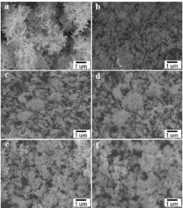
Figure 1. SEM images of (a) Cu, (b) SnSb, (c) SnSbCu0.1, (d) SnSbCu0.2, (e) SnSbCu0.3 and (f)
SnSbCu0.4.
[image:3.596.165.431.355.656.2][image:4.596.155.438.135.384.2]
incompact structure with some gaps and voids after the introduction of Cu. The average particle size is increased and the surface of the particle becomes smooth as the incremental of Cu content.
Figure 2. XRD patterns of the (a) SnSb and (b) SnSbCu0.3 anode materials.
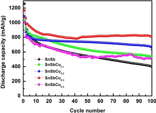
Figure 3. Cycling performance of SnSbCux (x=0, 0.1, 0.2, 0.3, 0.4) composite materials.
Fig. 2 shows the XRD pattern of the pristine SnSb and SnSbCu0.3 composite material,
[image:4.596.143.451.447.669.2]
the introduction of Cu, the peaks from pure Sn and SnSb alloy are gradually weaken, while peaks at 30.02° and 42.82° appear, corresponding to Cu6Sn5 phase [19].
The cycling performance of the SnSbCux composite materials were evaluated by galvanostatic charge/discharge between 0 to 2.0 V at a constant current density of 0.1 mA/cm2 for 100 cycles. As shown in Fig. 3, the discharge capacity of composites is basically higher than that of pure SnSb alloy and the SnSbCu0.3 exhibits the best performance [20] that the initial discharge capacity is 1169.2
[image:5.596.142.455.236.467.2]mAg/h, the coulombic efficiency of first cycle exceeds 91.0% and the reversible capacity maintains at 821.5mAh/g after 100 cycles [21].
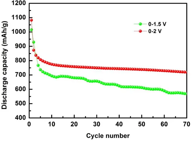
Figure 4. Cycling performance of SnSbCu0.3 over different voltage intervals.
Fig. 4 depicts cycling performance of SnSbCu0.3 at different voltage intervals. The discharge
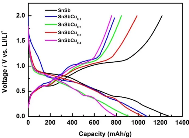
Figure 5. Initial charge/discharge profiles of the SnSbCux (x=0, 0.1, 0.2, 0.3, 0.4) alloy anode materials.
Figure 6. CV curves of (a) SnSb and (b) SnSbCu0.3 composite anode materials.
Fig. 5 shows the galvanostatic charge/discharge profiles of the SnSbCux alloy anode materials. It can be seen that all of them have several distinct voltage plateaus, corresponding to the formation of Li3Sb and a series of LixSn alloy [24], indicating that the Cu contents hardly affect the mechanisms of
[image:6.596.140.451.69.296.2] [image:6.596.77.520.367.530.2]
The CV curves of SnSb and SnSbCu0.3 composite materials were tested at a scan rate of 0.02
mV/s over a voltage range of 0-2.0 V (vs. Li/Li+). As shown in Fig. 6a and 6b, respectively. The reproducibility for the 2nd and 3rd cycle is very good, the shape of peaks are almost the same, indicating relatively good cyclic reversibility [26]. And the addition of Cu to SnSb alloy showed different electrochemical properties. For the cathodic scan, a reduction peak is found in the first cycle at 1.0 to 1.5 V. However this peak disappears in further cycles, which is generally attributed to the reduction of tin oxides and the solid electrolyte interface (SEI) film formation film on the electrode surface by electrolyte decomposition [27]. The significant reduction peak close to 0.8 V and persists through following cycles is generally attributed to the Li+ alloying with SnSb. The Li+ get into reaction with Sb in the SnSb alloy to form Li3Sb, while the metallic tin is released at the same time. And a
series of peaks appear after 0.66 V, contributing to the different LixSn phase which was formed by the
reaction of Sn with lithium. The broad peak on the subsequent anodic scan curve at 0.875 V corresponds to the formation of SnSb alloys and the delithiation of LixSb, respectively. It can be found
that both anode materials are involved in two lithiation/delithiation reactions [28]: Sn+xLi→LixSn (0<x≤4.4) (1)
SnSb+3Li++3e−→Li3Sb+Sn (2)
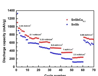
[image:7.596.71.540.88.598.2]Figure 7. Specific capacities of the SnSb and SnSbCu0.3 electrodes at different C rates.
Fig. 7 shows the specific capacities of the SnSb and SnSbCu0.3 at different C rates (1 C =800
mAh/g). The results indicated that the SnSbCu0.3 alloy material exhibited improved electrochemical
performance at different C rates compared with SnSb alloy. The anodes were discharged at increasing current density for 10 cycles [29]. The average specific capacities at 0.05, 0.1, 0.25, 0.5, 1and 2.5 mAh/cm2 gradually declined, and the initial discharge capacities for SnSb and SnSbCu0.3 are 1330.2
[image:7.596.135.459.343.596.2]
capacities of two electrodes after 60 cycles are 125.6 and 242 mAh/g, respectively and when the current density decreased from 2.5 to 0.05 mAh/cm2, the discharge specific capacities accumulated that the discharge capacities for SnSb and SnSbCu0.3 are 657.4 and 778.4 mAh/g with response rates of
[image:8.596.142.452.166.397.2]72.7% and 80.6%.
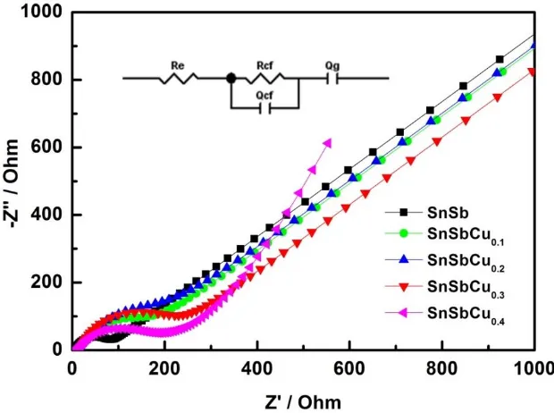
Figure 8. EIS of SnSbCux (x=0, 0.1, 0.2, 0.3, 0.4) at the open circuit voltage.
Fig. 8 shows the impedance spectra of SnSbCux composite anodes at open-circuit voltage, which displayed a depressed semicircle linked with a sloping line. All the spectra of the composite anodes are very similar and the formation of the SEI layer is increased with the Cu content increased due to the uncompact feature that the organic electrolyte can evenly dispersed into the particles in the composite electrodes. In the equivalent circuits, Qg represents the resistance of Li+ diffusion, Rs is the
organic electrolyte impedance, Qcf and Rcf are the contact resistances (inset of Fig. 8) were fitted with
[image:8.596.110.483.627.705.2]the experimental data, and the results are shown in Table 1.
Table 1. Fitting results of the SnSbCux material before cycling at the open-circuit voltage.
SnSbCux 0 0.1 0.2 0.3 0.4
Rs (Ω) 2.75 6.30 5.43 8.26 9.32
Figure 9. EIS of SnSbCu0.3 electrode after different cycles
As shown in Fig. 9, the impedance of SnSbCu0.3 electrode after different cycles increased
compared to the results obtained before discharging. The reason is that volume expansion has taken place in the composite anodes during electrochemical reactions, resulting in a breakdown of the alloy anodes [30]. And with coverage by the shredded powders on surface, the Li+ ions were blocked and caused an increased internal resistance. Therefore the interfacial impedance increased with the cycling.
[image:9.596.144.454.71.305.2] [image:9.596.134.465.450.699.2]
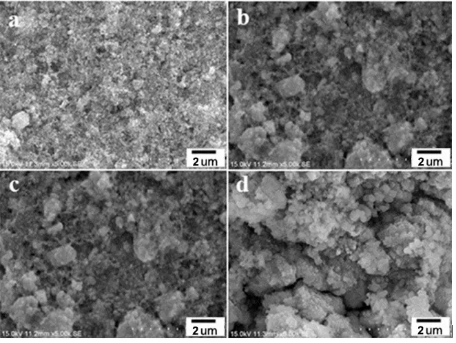
Fig. 10 shows the apparent morphology of SnSbCu0.3 alloy electrode before and after different
cycles. The SnSbCu0.3 composite anode materials were fully penetrated on the current collector due to
the presence of larger, irregular Cu particles, which prevents aggregation of nanoparticles before discharge (Fig. 10a). A dense SEI layer was formed on the surface of the electrode after 10 cycles, and volume expansion occurred that the aggregation of alloy particles expanded, as shown in Fig. 10b. And there are visible cracks on the surface which is probably caused by the shredding of active material, therefore, increasing diffusion distance of Li+ ions between the particles.
4. CONCLUSIONS
In summary, the SnSbCux (x=0, 0.1, 0.2, 0.3, 0.4) alloy materials were synthesized by chemical reduction, and this method is beneficial for reducing the particle’s size to produce nano-sized composite material. SEM results showed an incompact structure with uniform distribution of the particles. XRD results indicated the presence of pristine SnSb and Cu6Sn5 phase [30]. The introduction
of Cu into the binary SnSb alloy system increased electrical conductivity, minimized the volume change of particles during charge/discharge process and inhibited of the phenomenon of powder cracking, resulting in increase of cyclic stability [31]. The SnSbCu0.3 composite alloy anode material
showed the best cycling performance, with an initial discharge capacity of 1280.1 mAg/h and the coulombic efficiency of over 91.0%. The reversible capacity maintained at 814.1 mAh/g and the capacity retention exceeds 77.2% after 100 cycles, so the composite has a fairly high reversible capacity and a quite stable cycle ability. SnSbCux ternary composite materials are potential candidates as anode materials for high performance lithium-ion batteries.
ACKNOWLEDGEMENTS
This work was financial supported by the National Natural Science Foundation of China (51374146, 51502177, 21471100), the Natural Science Foundation of Guangdong (2015A030313542, 2014A030310323) and the Shenzhen Dedicated Funding of Strategic Emerging Industry Development Program (JCYJ20140418182819155, JCYJ20140418182819158).
References
1. S. Yoon, J.-M. Lee, H. Kim, D. Im, S.-G. Doo and H.-J. Sohn, Electrochim. Acta, 54 (2009) 2699. 2. C.-C. Chang, Y.-C. Chen, C.-W. Huang, Y.H. Su and C.-C. Hu, Electrochim. Acta, 99 (2013) 69. 3. G. Fang, S. Kaneko, W. Liu, B. Xia, H. Sun, R. Zhang, J. Zheng and D. Li, Electrochim. Acta, 111
(2013) 627.
4. D. Guan, J. Li, X. Gao and C. Yuan, J. Alloys and Compd., 617 (2014) 464.
5. B. Philippe, A. Mahmoud, J.B. Ledeuil, M.T. Sougrati, K. Edström, R. Dedryvère, D. Gonbeau and P.E. Lippens, Electrochim. Acta, 123 (2014) 72.
6. L. Xue, X. Xia, T. Tucker, K. Fu, S. Zhang, S. Li and X. Zhang, J. Mater. Chem. A, 1 (2013) 13807. 7. L. Baggetto, H.-Y. Hah, J.-C. Jumas, C.E. Johnson, J.A. Johnson, J.K. Keum, C.A. Bridges and
G.M. Veith, J. Power Sources, 267 (2014) 329.
Solid State Sci., 19 (2013) 144.
10. Y. Wang, P. Zhang, X. Ren and G. Yi, J. Electrochem. Soc., 158 (2011) 1404. 11. Q. Jiang, R. Xue and M. Jia, Appl. Surf. Sci., 258 (2012) 3854.
12. R. Yang, J. Huang, W. Zhao, W. Lai, X. Zhang, J. Zheng and X. Li, J. Power Sources, 195 (2010) 6811.
13. F. Wang, M. Zhao and X. Song, J. Power Sources, 175 (2008) 558.
14. M. Arpacık, M. Bicer and I.Sismanz, J. Electrochem. Soc., 160 (2013) A2251.
15. Z. Zhang, C. Zhou, Y. Liu, J. Li, Y. Lai and M. Jia, Int. J. Electrochem. Sci., 8 (2013) 10059. 16. Y. Wang, P. Zhang, X. Ren and G. Yi, Int. J. Electrochem. Sci., 10 (2015) 9652.
17. H. Li, L. Shi, W. Lu, X. Huang and L. Chen, J. Electrochem. Soc., 148 (2001) A915. 18. J. Li, M. Zhou, Y. Zhao, Z. Huang and L. Guan, J. RSC Adv., 3 (2013) 19251. 19. I.-S. Jeong, J.-U. Kim, and H.-B. Gu, J. Power Sources, 102 (2001) 55.
20. R. Qiang, X. Chen, J. Li, L. Guo, and S. Hu, Electrochim. Acta, 193 (2016) 180. 21. Y. Li, W. Zhang, H. Cai, J. Wang, X. Ren and P. Zhang, RSC Adv., 5 (2015) 128. 22. S. Fürtauer, and H. Flandorfer, J. Alloys and Compd., 682 (2016) 713.
23. Q. Jiang, D. Hu, M. Jia and R. Xue, Appl. Surf. Sci., 321 (2014) 109. 24. F. Wang, M. Zhao, and X. Song, J. Power Sources, 175 (2008) 558.
25. P. Nithyadharseni, M.V. Reddy, B. Nalini and B.V.R. Chowdari, Mater. Lett., 150 (2015) 24. 26. L. Feng, Z. Xuan, S. Ji, W. Min, H. Zhao and H. Gao, Int. J. Electrochem. Sci., 10 (2015) 2370. 27. P. Zhang, Y. Wang, J. Wang, D. Zhang, X. Ren and Q. Yuan, Electrochim. Acta, 137 (2014) 121. 28. J. Li, Q. Ru, S. Hu, D. Sun, B. Zhang and X. Hou, Electrochim. Acta, 113 (2013) 505.
29. S.M. Becker, I. Issac, R. Heinzmann, M. Scheuermann, A. Eichhöfer, D. Wang, V.S.K.
Chakravadhanula, C. Kübel, A.S. Ulrich, H. Hahn and S. Indris, J. Power Sources, 229 (2013) 149. 30. X. Chen, R. Qiang, D. Zhao, Y. Mo and S. Hu, J. Alloys and Compd., 646 (2015) 794.
31. J.C. Kim and D.W. Kim, Chem. Asian. J., 9 (2014) 3313.