Abstract— This paper presents a dual Modular Multilevel Converter (MMC) topology that utilizes energy exchange between adjacent arm Sub-Modules (SM), operating with out-of-phase modulation. The proposed configuration is
applicable to medium-voltage, high-power variable-speed drives incorporating open-end stator winding machines. A novel
concept of power redistribution between adjacent SMs in the dual MMC topology is realized through high-frequency
transformer-based dc-dc converter modules. This concept offers a significant reduction in the sizing requirement of the
SM capacitance and the stored energy in the MMC system, while avoiding the problem of wide voltage fluctuations of SM
capacitors, especially at low operating frequencies. The proposed configuration can produce dc voltage, therefore, a
machine speed-range from zero speed to the rated speed is possible under the rated torque operating condition. The
operating principles of the proposed dual MMC configuration are elaborated and necessary mathematical analysis is
derived. Simulation and experimental results verify the concept of the proposed drive configuration.
Index Terms— Dual Half-Bridge (DHB), high-frequency transformer, low motor speed, Medium-Voltage (MV) variable-speed drives, Modular Multilevel Converter (MMC), open-end stator winding machines, Sub-Module (SM) capacitor voltage ripple.
I. INTRODUCTION
Interest in the Modular Multilevel Converter (MMC) has been steadily grown due to its promising potential, enabling it to be
suitable for medium- to high-voltage, high-power applications such as High-Voltage Direct-Current (HVDC) transmission and
Medium-Voltage (MV) motor drive applications [1]-[10]. The salient features of the MMC can be summarized in its high
modularity, ease of scalability, and enhanced reliability. In addition to its merits, the shortcomings of classical multilevel converter
topologies, such as diode-clamped [11], flying-capacitor [12], and cascaded H-bridge converters [13], result in the MMC being the
standard commercialized converter interface in the HVDC field, but not yet in MV adjustable-speed drive applications. The main
reason is that MMC-fed adjustable-speed drives suffer from power imbalance problems between the upper and lower arms when
operating at high-torque and low-speed conditions, where the voltage fluctuations of the MMC floating capacitors is directly
proportional to the magnitude of the output current, while inversely proportional to the operating frequency. With this serious
A Dual Modular Multilevel Converter with
High-Frequency Magnetic Links Between Sub-Modules for
MV Open-End Stator Winding Machine Drives
challenge, the MMC is not suitable to drive a motor at a constant torque while Volt/Hertz control is applied, which constrains its
application in a narrow range of quadratic-torque loads such as fans, pumps, and compressors [14], [15].
Reviewing the literature, several approaches have been proposed to restrain the inherent problem of wide voltage fluctuations of
the MMC floating capacitors at low operating frequencies. The most effective approach to suppress the capacitor voltage-ripple is
to inject a high-frequency circulating current into the MMC phase arms, while injecting the same frequency harmonic into the
converter output Common-Mode Voltage (CMV) [16]-[25]. With this approach, two degrees of freedom are created and can be
exploited to redistribute the power between the upper and lower MMC arms, where both injected signals produce a high-frequency
power exchange between the arms, allowing the Sub-Module (SM) capacitors to be charged and discharged more frequently such
that their voltage ripple is attenuated. In order to reduce the peak of the injected signals, and hence to reduce losses, the injected
circulating current waveform is reshaped from sinusoidal waveform [16]-[20] into a square waveform [21]-[24] and third-order
current harmonic as well [25]. Although this compensation approach limits capacitor voltage variation at low motor speeds, the
CMV introduced at the motor terminals results in insulation and bearing current problems that harm the motor and shorten its
lifetime. Also, the high magnitude of the high-frequency arm currents significantly increases current stress, and consequently
power loss, which necessitates oversizing the current rating of the switching devices. In addition, a conflict in coordinating the
control of the intentionally injected signals and the basic MMC control loops may arise, causing stability problems during transient
conditions.
Revisiting other approaches that address MMC low-frequency operation through the proposal of new control methods, operation
modes, or modulation techniques; an approach which applies a flexible control scheme for MMC capacitor voltage as a motor
driver was proposed in [26] and [27]. In this approach, the SM capacitor voltage can be varied in accordance to the motor speed
by regulating both the dc and ac components of the Pulse-Width Modulation (PWM) reference signal, which allows increasing
capacitor voltage-ripple as the motor speed decreases without exceeding the maximum peak capacitor voltage. Asymmetric MMC
operation, to avoid dc-link voltage influence on the capacitor ripple, was presented in [28]. By forcing one arm to apply the major
dc-link voltage renouncing the contribution in output current generation, the other arm sustains almost all output current with a
low dc-link voltage. The quasi two-level MMC operation, proposed in [29], has been extended to triangle-carrier based PWM in
order to synthesize low-frequency output waveforms as in the conventional two-level PWM voltage source inverter, which reduces
branch energy variations [30].
On the other hand, various modifications to the basic MMC structure have been adopted to tightly control capacitor
voltage-ripple at low-frequency operation of adjustable-speed drives. A power transfer channel has been introduced to provide power
balance between the upper and lower MMC arm by a cross connection of the middle taps of both arms through an additional path
a high-frequency voltage is introduced into the sub-arms, which excites a high-frequency current in the additional cross-connected
path to create one degree of freedom for power redistribution between both the upper and lower arms. Other configurations address
MMC low-frequency operation by employing full-bridge SMs instead of the HB-SMs [33], suggesting an MMC-based Hexverter
topology for energy-balance control [34], combining the conventional MMC configuration with a series switch to the dc input
source to reduce the average dc components in the arm voltages by disconnection of the dc source at regular intervals [35], and
connecting the capacitors of the top SMs and the bottom SMs via two accessorial cables, while connecting the upper and lower
arms through a central SM [36].
Nonetheless, all of the abovementioned approaches are unable to drive a machine at full-load and zero-speed conditions. Also,
most studies address low-frequency operation of MMC-fed variable-speed drives as a transient condition during starting instead
of considering it as a continuous operating condition. Moreover, no further detailed verification and results have been presented
for high-power machines with multi-megawatt drive systems.
To provide a reliable solution that overcomes the discussed limitations of MMC-fed variable-speed drives, this paper proposes a
dual MMC configuration for MV high-power variable-speed drives incorporating an open-end stator winding machine. The
concept of the proposed configuration is inspired by the adverse coupling and interaction between arm stored-energies. For
instance, if the upper arm needs to charge energy, the lower arm needs to discharge the same amount of energy. That is, the
proposed configuration allows a bidirectional energy exchange between each pair of arms of the dual MMC, operating with
out-of-phase modulation, through modular isolated dc-dc converters interfacing each front-to-front SM. With bidirectional energy
exchange between adjacent SMs, the capacitive energy is evenly redistributed among adjacent arms in the same dual leg,
eliminating the wide variation of capacitor voltage-ripple independent of the operating frequency. This allows the MMC to drive
a variable-speed machine at constant torque over the whole speed range, even at stand-still condition. Although the proposed
configuration adds hardware to the basic MMC structure, it significantly reduces the SM capacitance, and hence, the energy stored
in the MMC system. Further, the control of the added energy-exchange modules is independent of the main MMC system control
loops.
The outline of this paper is as follows. Section II addresses the operating principles of the dual MMC topology for open-end stator
winding machines. The proposed dual MMC configuration, with bidirectional energy exchange dc-dc converter modules, is
illustrated in Section III. Simulation results for multi-megawatt MMC systems are presented in Section IV, while experimental
results for a scaled-down laboratory prototype are presented in section V. Assessment of the proposed MMC configuration is
II. DUAL MMC TOPOLOGY FOR OPEN-END STATOR WINDING MACHINES
Machines with open-end stator windings are a possible alternative to conventional star- and delta-connected stators, that not only
suppress switching CMVs but also improve output voltage quality [37]-[41]. The concept of employing a dual-inverter
configuration feeding each end of an open-end stator winding of an induction motor was first introduced in [42] for MV
high-power applications. The topology has been implemented using two two-level inverters, while it is capable of generating three-level
output voltage with half the dc-link voltage compared to a single-sided three-level inverter topology. Similarly, a dual three-level
inverter configuration with a single dc-link voltage was proposed for five-level operation [43]. Thereafter, several multilevel
topologies have been considered for open-end stator winding machines with various topologies [44]-[47]. Recently, a dual inverter
configuration based on the MMC has been proposed with many advantages [48], where it offers single dc-source operation
regardless of the number of output voltage levels, which eliminates bulky and expensive phase-shifting multi-winding isolation
transformers to provide isolated dc sources. Also, the dual MMC configuration achieves the same maximum output
voltage-magnitude as the conventional single-sided MMC with half of the dc-link voltage, which reduces the insulation requirement. If
one converter fails, the other converter can continue operation with a reduced output power while reconfiguring the machine
end-terminals at the faulty-converter side to be connected in star or delta, which gives the dual configuration an intrinsic fault-tolerant
capability. Moreover, it offers higher redundant switching state combinations compared to single-inverter-fed drives of the same
[image:4.612.48.574.426.665.2]number of output voltage levels, which can be exploited in the voltage balancing of the floating capacitors.
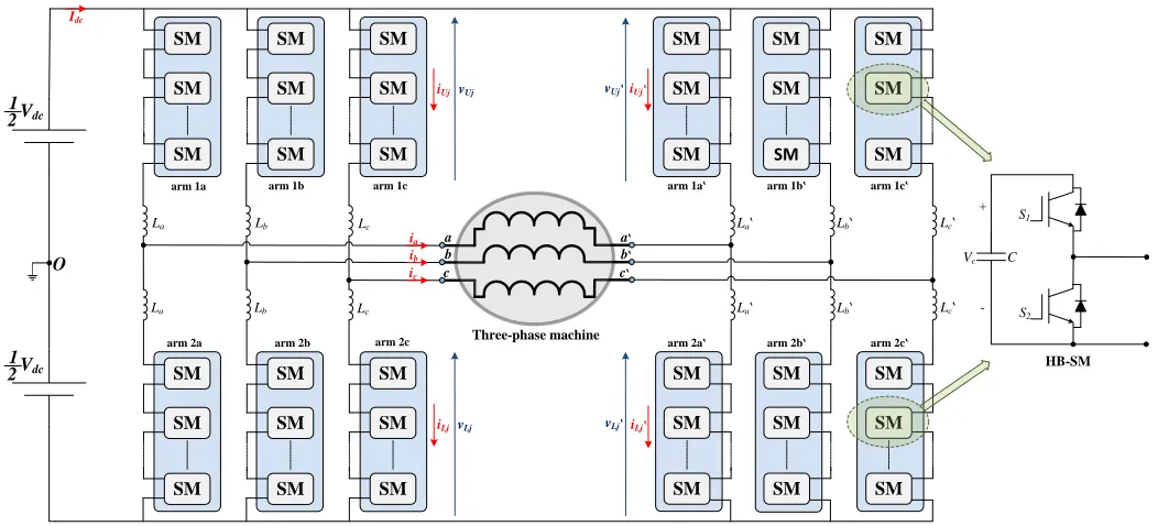
Fig. 1 Circuit configuration of a three-phase dual MMC-fed open-end stator winding machine.
Vdc a b c La La Lb Lb Lc Lc arm 1a arm 1b arm 1c
arm 2a arm 2b arm 2c
SM SM SM SM SM SM SM SM SM SM SM SM SM SM SM SM SM SM a b c Three-phase machine SM SM SM SM SM SM SM SM SM SM SM SM SM SM SM SM SM SM La La Lb Lb Lc Lc arm 1a arm 1b arm 1c
arm 2a arm 2b arm 2c
Vdc
O
iLj
iUj vUj
vLj iLj
The circuit diagram of a three-phase dual MMC configuration is shown in Fig. 1, where it consists of an MMC feeding each end
of the machine stator windings, while both MMCs operate in an out-of-phase manner. Each MMC is composed of three-phase legs
each of which consists of two arms connected in series through arm inductors. Each arm consists of N SMs connected in series, while the SM commonly consists of a HB cell with a dc capacitor of an equivalent capacitance C and a rated voltage 𝑉𝑐. Although
the number of arm inductors is doubled compared to the conventional single-sided MMC topology, the equivalent arm inductance
of the dual MMC topology remains the same. The dual MMC structure can be considered a direct consequence of splitting each
phase-leg of a conventional single-sided MMC into dual complemented legs each of half the number of series-connected SMs,
compared to the single-sided phase leg. Thus, for the same amount of power, the total number of SMs employed in a dual MMC
configuration is same as the number of SMs in a conventional single-sided topology. Additionally, the voltage and current stress
of the SM capacitors and switching devices is identical in both MMC configurations.
A. Basic Circuit Analysis
Referring to Fig. 1, the terminals of the open-end machine windings connected to the left MMC are denoted by 𝑎, 𝑏, 𝑐, while
𝑎′, 𝑏′, 𝑐′will represent the terminal-ends connected to the right MMC. The voltage across each phase-winding is the differential
voltage between both machine-winding ends, and denoted by 𝑣𝑗𝑗′, while the current through the machine winding is denoted by 𝑖𝑗,
where 𝑗 ∈ {𝑎, 𝑏, 𝑐}, and are given as follows.
𝑣𝑗𝑗′=𝑉𝑜cos(𝜔𝑡 + 𝜃𝑗) (1a)
𝑖𝑗=𝐼𝑜cos(𝜔𝑡 + 𝜃𝑗− ∅) (1b)
where 𝜔 is the output angular frequency, 𝜃𝑗 is the phase angle of the stator voltage (𝜃𝑎= 0⁰, 𝜃𝑏= 120⁰, and 𝜃𝑐= 240⁰), and ∅
is the machine power-factor angle. 𝑉𝑜 and 𝐼𝑜 are the magnitudes of the voltage across the machine windings and their current’s,
respectively. The magnitude of the ac output voltage is bounded by the modulation index 𝑀 and the voltage of the input source
𝑉𝑑𝑐 as in (2). It is worth noting that the utilization of the dc-link voltage is doubled with the dual-converter configurations, compared
to a single-sided topology.
𝑉𝑜= 𝑀𝑉𝑑𝑐 (2)
Since each two MMC legs feeding a given machine phase-winding have out-of-phase modulation, the reference voltages for
different MMC arms in both converters in addition to the arm currents are given by (3) and (4), respectively, with the subscripts U and L referring to the corresponding ‘upper’ and ‘lower’ arm.
𝑣𝑈𝑗 = 𝑣𝐿𝑗′=
1
2𝑉𝑑𝑐− 1
2𝑣𝑗𝑗′
𝑣𝐿𝑗= 𝑣𝑈𝑗′= 1 2𝑉𝑑𝑐 +
1
2𝑣𝑗𝑗′ (3b)
𝑖𝑈𝑗 = 𝑖𝑐𝑚 𝑗+
1
2𝑖𝑗 , 𝑖𝐿𝑗= 𝑖𝑐𝑚 𝑗−
1
2𝑖𝑗 (4a)
𝑖𝑈𝑗′= 𝑖𝑐𝑚 𝑗′−
1
2𝑖𝑗 , 𝑖𝐿𝑗′ = 𝑖𝑐𝑚 𝑗′+
1 2𝑖𝑗
(4b)
where 𝑖𝑐𝑚 𝑗 and 𝑖𝑐𝑚 𝑗′ are the Common-Mode (CM) currents of each two complemented legs in the dual MMC topology, and often
referred to as circulating currents. Ideally, these CM currents should be equal to a constant dc-component which depends on the
number of MMC-legs and the active power delivered from or to the dc-link. However, the mutual interaction between the arm
inductors and the SM capacitors induces a series of even-order harmonics that appear in an out-of-phase profile in both CM currents
[49]. With appropriate even-order harmonic suppression control [50], [51], both CM currents can be considered as only a dc
component which can be calculated for a dual three-phase MMC through lossless power balance between the dc input and ac
output as shown in (5), with 𝐼𝑑𝑐 is the dc input current of the dual MMC.
𝑖𝑐𝑚 𝑗= 𝑖𝑐𝑚 𝑗′=
𝐼𝑑𝑐
6 =
𝑀𝐼𝑜cos ∅
4 (5)
B. Energy Variation Analysis
In this subsection, the analysis of energy variation is conducted for a general phase-leg, j, of the left MMC. The same analysis applies to the other phase-legs, denoted by j′ of the right MMC, however, in an out-of-phase manner. The instantaneous power input to each arm is given by the product of the arm voltages (3) and the corresponding arm currents (4):
𝑝𝑈𝑗 = 𝑣𝑈𝑗 𝑖𝑈𝑗 = (
1
2𝑉𝑑𝑐−
1
2𝑉𝑜𝑐𝑜𝑠(𝜔𝑡 + 𝜃𝑗)) (𝑖𝑐𝑚 𝑗+
1
2𝑖𝑗 ) (6a)
𝑝𝐿𝑗= 𝑣𝐿𝑗 𝑖𝐿𝑗= (
1
2𝑉𝑑𝑐+
1
2𝑉𝑜𝑐𝑜𝑠(𝜔𝑡 + 𝜃𝑗)) (𝑖𝑐𝑚 𝑗−
1
2𝑖𝑗 ) (6b)
Substituting (1), (2), and (5) into (6) yields,
𝑝𝑈𝑗 =
𝑉𝑑𝑐 𝐼𝑜
4 [cos(𝜔𝑡 + 𝜃𝑗− ∅) −
𝑀2
2 𝑐𝑜𝑠(∅) 𝑐𝑜𝑠(𝜔𝑡 + 𝜃𝑗) −
𝑀
2 𝑐𝑜𝑠[2(𝜔𝑡 + 𝜃𝑗) − ∅] ] (7a)
𝑝𝐿𝑗=
𝑉𝑑𝑐 𝐼𝑜
4 [−cos(𝜔𝑡 + 𝜃𝑗− ∅) +
𝑀2
2 𝑐𝑜𝑠(∅) 𝑐𝑜𝑠(𝜔𝑡 + 𝜃𝑗) −
𝑀
2 𝑐𝑜𝑠[2(𝜔𝑡 + 𝜃𝑗) − ∅] ] (7b)
The instantaneous power in the upper and lower arms can be categorized into a CM component, 𝑝𝑐𝑚, which is in phase in both
arms, and a Differential-Mode (DM) component, 𝑝𝑑𝑚, which is anti-phase in the upper and lower arms. The CM component
alternates at twice the line frequency, and is a direct consequence of the active power at the dc-side is constant, whereas the
phase-power at the ac-side pulsates at twice the line frequency. The DM component alternates with the fundamental line-frequency, and
𝑝𝑐𝑚= −
𝑉𝑑𝑐 𝐼𝑜𝑀
8 𝑐𝑜𝑠[2(𝜔𝑡 + 𝜃𝑗) − ∅] (8a)
𝑝𝑑𝑚 =
𝑉𝑑𝑐 𝐼𝑜
4 [cos(𝜔𝑡 + 𝜃𝑗− ∅) −
𝑀2
2 𝑐𝑜𝑠(∅) 𝑐𝑜𝑠(𝜔𝑡 + 𝜃𝑗) ] =
𝑉𝑑𝑐 𝐼𝑜
8 √4 + cos
2(∅)(𝑀4− 4𝑀2) 𝑐𝑜𝑠(𝜔𝑡 + 𝜃
𝑗− 𝛾) (8b)
𝛾 = ∅ + tan−1𝑀
2tan ∅ cos2∅
2 − 𝑀2cos2∅ (9)
Similar to the instantaneous power, the energy variation of the arms can be classified into a CM component, 𝑤𝑐𝑚, and a DM
component, 𝑤𝑑𝑚, as given by (10).
𝑤𝑈𝑗= 𝑤𝑐𝑚+ 𝑤𝑑𝑚 (10a)
𝑤𝐿𝑗= 𝑤𝑐𝑚− 𝑤𝑑𝑚 (10b)
where 𝑤𝑈𝑗 and 𝑤𝐿𝑗 are the alternating components of the stored energy in the upper and lower arms, respectively. Integrating (8)
yields both energy variation components as follows.
𝑤𝑐𝑚= −
𝑉𝑑𝑐 𝐼𝑜𝑀
16𝜔 𝑠𝑖𝑛[2(𝜔𝑡 + 𝜃𝑗) − ∅] (11a)
𝑤𝑑𝑚=
𝑉𝑑𝑐 𝐼𝑜
8𝜔 √4 + cos
2(∅)(𝑀4− 4𝑀2) 𝑠𝑖𝑛(𝜔𝑡 + 𝜃
𝑗− 𝛾) (11b)
C. Capacitor Voltage Analysis
Due to the dual frequency alternation of the capacitive energy stored in the MMC arms, capacitor voltage fluctuations have both
CM and DM voltage-ripple components alternating at twice the fundamental frequency and at the fundamental frequency,
respectively, as shown by (12).
∆𝑣𝑐𝑈𝑗= −∆𝑉𝑐 𝑐𝑚
2 𝑠𝑖𝑛[2(𝜔𝑡 + 𝜃𝑗) − ∅] +
∆𝑉𝑐 𝑑𝑚
2 𝑠𝑖𝑛(𝜔𝑡 + 𝜃𝑗− 𝛾) (12a)
∆𝑣𝑐𝐿𝑗= −∆𝑉𝑐 𝑐𝑚
2 𝑠𝑖𝑛[2(𝜔𝑡 + 𝜃𝑗) − ∅] −
∆𝑉𝑐 𝑑𝑚
2 𝑠𝑖𝑛(𝜔𝑡 + 𝜃𝑗− 𝛾) (12b)
where ∆𝑣𝑐𝑈𝑗 and ∆𝑣𝑐𝐿𝑗 are the capacitor voltage variation of SMs in the upper and lower arms of the left MMC, respectively, while
∆𝑉𝑐 𝑐𝑚 and ∆𝑉𝑐 𝑑𝑚 are the absolute values of the peak-to-peak variation of the CM and DM components of the SM capacitor
voltage-ripple. That is, the variation of the arm stored-energy is handled by the capacitors of the series-connected SMs in each arm as
demonstrated by (13).
∆𝑊 =𝑁𝐶
2 (𝑉
2
𝑐 𝑚𝑎𝑥− 𝑉2𝑐 𝑚𝑖𝑛) = 𝑁𝐶𝑉𝑐 ∆𝑉𝑐 (13)
Since the average voltage across each SM capacitor is 𝑉𝑐= 𝑉𝑑𝑐/𝑁, then the magnitude of the peak-to-peak capacitor voltage-ripple
due to CM and DM components, from (11) and (13) are:
∆𝑉𝑐 𝑐𝑚=
𝐼𝑜𝑀
8𝜔𝐶 (14a)
∆𝑉𝑐 𝑑𝑚=
𝐼𝑜
4𝜔𝐶√4 + cos
2(∅)(𝑀4− 4𝑀2) (14b)
The CM component of the capacitor voltage-ripple is a direct result of the CM power given by (8a), which is inherited in the
converter due to the different frequency of the input and output power. Although this CM component is inevitable, it has a slight
influence on the capacitor voltage-ripple as demonstrated by (14a), where in variable-speed drives with Volt/Hertz control, the
ratio 𝑀/𝜔 is near constant, while the load current 𝐼𝑜 is invariant. On the other side, when the operating frequency 𝜔 is reduced in
(14b), while the ratio 𝑀/𝜔 is constant for constant motor torque requirements, the DM component of the capacitor voltage-ripple
increases. Furthermore, the direct proportionality of capacitor voltage-ripple to output current variation at a constant operating
frequency is much higher in the DM component, compared to the CM component. The significant influence of the DM component
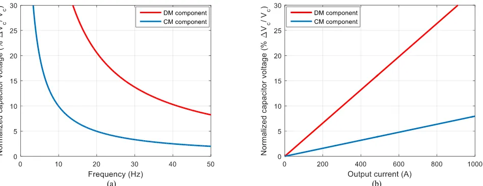
in the capacitor voltage-ripple can be emphasized as in Fig. 2, where the normalized peak-to-peak capacitor voltage-variation, for
both CM and DM components, is illustrated with operating frequency variation in Fig. 2a, and with output current variation in Fig.
2b.
[image:8.612.67.541.423.606.2](a) (b)
Fig. 2 Normalized components of capacitor voltage-ripple, with 𝑉𝑐= 2.5 kV, C =3 mF, M = 0.75, and ∅ =25⁰, at (a) variable frequency and constant output current
(Io =500 A) and (b) variable output current and constant frequency (f = 25 Hz).
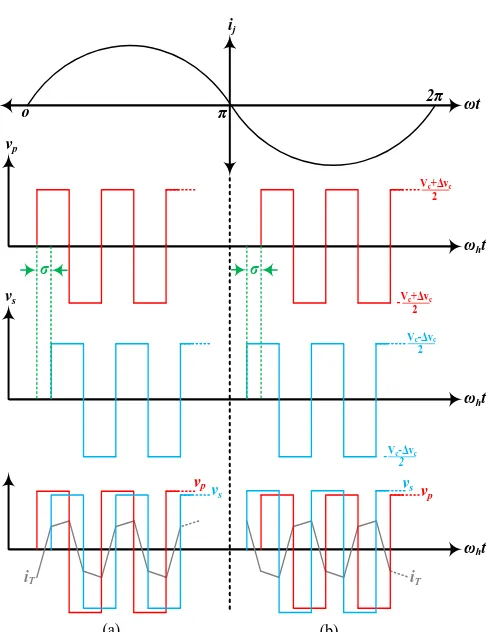
Further assessment of the two components of the capacitor voltage-ripple is elucidated in Fig. 3, where the variation of the
normalized capacitor voltage-ripple for both components is shown with operating frequency variation at different output currents,
while the ratio 𝑀/𝜔 is constant as required by Volt/Hertz control. The CM component of the capacitor voltage-ripple exhibits a
component is slightly affected by a corresponding increase in the output current from 200 A to 1000 A. In contrast, the ripple
profile of the capacitor voltage DM component is significantly increasing at low operating frequencies, while approaching infinity
at near zero frequency. In addition, the DM voltage-ripple is much increased as the output current increases. The conclusion is that
the dominant component of capacitor ripple is the DM, which should be tightly controlled so that the capacitor
[image:9.612.177.433.168.374.2]voltage-ripple does not exceed tolerated values.
Fig. 3 Normalized components of capacitor voltage-ripple at constant 𝑀/𝜔. (C =3 mF, 𝑉𝑐= 2.5 kV, and ∅ =25⁰).
III. PROPOSED DUAL MMC CONFIGURATION WITH ENERGY-EXCHANGE MODULES
The analysis establishes that the major obstacle for wide frequency-range applications of MMCs is the inherent fundamental component in the pulsating power and stored energy of the MMC’s arms. This fundamental component is referred to as the DM
component, which produces wide voltage-fluctuations across the SMs’ capacitors as shown in Fig. 2 and Fig. 3. When the speed
of the machine drops or the developed torque increases, the DM component tends to produce larger voltage fluctuations on the SM
capacitor, while approaching infinity, theoretically, at speeds/frequencies near zero. Accordingly, the most reliable solution for
low-frequency MMC operation is to eliminate the DM component inherited in the energy stored in MMC arms.
The dual MMC topology, illustrated in Section II, infers each machine phase-winding be connected differentially between two
MMC legs modulated out-of-phase. This out-of-phase modulation associated with a common machine-winding keeps the DM
component of the energy stored in one MMC arm to alternate with an opposite phase to the same energy component stored in the
adjacent arm of the complemented leg. Therefore, a scheme to eliminate the DM component in MMC arms is to create a
bidirectional energy exchange path between opposite arms in the same dual-leg. Since the energy stored in each MMC arm is
equally shared by all SMs subsisted by this arm through an individual capacitor voltage balancing technique, a modular
implementation of energy exchange between opposite arms in each dual leg can be achieved by inserting high-frequency (HF)
the stored capacitive-energy among each front-to-front SM by transferring the DM power component from the SM with arm current
charging its capacitor into the adjacent SM with a discharging current-direction. With such bidirectional energy transfer between
adjacent SMs, the DM component of energy variation can be cancelled, while the CM component is evenly distributed. This
approach is illustrated in Fig. 4, where, for brevity, one phase-leg of the proposed three-phase dual MMC topology is shown.
A. Bidirectional Isolated DC-DC Converter Modules
The concept of dc-dc conversion via a HF transformer, proposed in [52], can achieve high power-density dc-dc conversion with
bidirectional power-flow, galvanic isolation, high efficiency, low weight and size, and soft semiconductor switching. The
phase-shift dual-bridge converter is the common implementation of the HF transformer-based dc-dc converter, in which two
active-bridges are interfaced through a HF transformer, where the active-bridges are phase shifted relative to each other to control the power
transferred from one dc voltage tank to the other. Two configurations among the phase-shift dual-bridge dc-dc converters are the
phase-shift Dual Active-Bridge (DAB) and Dual Half-Bridge (DHB) converters [52]-[55]. In a comparison, the DHB topology has
half the switching devices and corresponding drivers for the same power rating resulting in an efficient power transfer. In addition,
the transformer flux-swing of the DHB is only half of DAB’s when the same switching frequency and effective cross-sectional
area of the transformer core are employed. Therefore, the phase-shift DHB is employed as a dc-dc energy-exchange module for
the proposed dual MMC configuration. A detailed circuit diagram for front-to-front SMs in the proposed dual MMC configuration
shown in Fig. 4 is elucidated in Fig. 5, where two HB MMC SMs are interfaced through a DHB dc-dc converter. The DHB
converter consists of two voltage-source HB dc-ac converters that are coupled to a HF isolation transformer. The turns ratio of the
transformer is 1:1 since the dc-dc conversion is only employed for energy exchange between bridge sides at the same voltage level, which is equal to the average voltage of the MMC’s SM capacitors. The leakage inductance of the transformer is utilized as an
interface and energy transfer element between the two voltage-source HB inverters, while the output capacitance of the switching
devices is used to realize soft-switching operation [56]. Both HB converters generate fixed-frequency square-wave voltages with
a constant duty ratio of 50%, applied to both transformer sides. The DHB configuration necessitates the capacitor of each SM be
equally split with access to the center-tap point as shown in Fig. 5.
The phase-shift angle, 𝜎, of the two square-wave voltages of the DHBs determine the amount of power transferred from the
leading bridge to the lagging one. With unity transformer turns-ratio and equal voltage levels 𝑉𝑐 at both bridge sides, the DHB
power is expressed as [55]:
𝑃 =𝑉𝑐
2𝜎(𝜋 − |𝜎|)
8𝜋2𝑓
ℎ𝐿
(15)
Referring to Fig. 5, the front-to-front SMs are assumed in the upper arms of a general dual phase-leg 𝑗𝑗′, where a positive
half-cycle of the output current charges the capacitor of a left-side (primary side) SM, while at the same time discharges the capacitor
of a right-side (secondary side) SM. Forward power-transfer, designated as a positive phase-shift, occurs during the positive
half-cycle of the MMC output current. In this case, the primary-side HB converter is the leading bridge while the secondary-side HB
converter is the lagging bridge. The same power transfer action is repeated during the negative half-cycle of the output current but
with the reversal of leading and lagging bridge sides, resulting in reverse power transfer, with a negative phase-shift. This is
elucidated in Fig. 6, where 𝑣𝑝 and 𝑣𝑠 are the voltages applied on the primary and secondary transformer sides respectively, 𝑖𝑇 is
the transformer current, and 𝜔ℎ is the angular high-frequency of the DHB switching devices. At any output current instant, the
direction of power flow between front-to-front SMs in upper arms is the reversed of the front-to-front SMs in lower arms of the
same dual-leg.
[image:11.612.52.299.279.581.2]Fig. 4 A circuit diagram for the proposed dual MMC configuration with energy-exchange modules between front-to-front SMs.
Fig. 5 DHB configuration for front-to-front HB SMs of the dual MMC topology.
(a) (b)
Fig. 6 Sketch map of the idealized waveforms of DHB converter for bidirectional power transfer between front-to-front MMC SMs. (a) Positive phase-shift angle and (b) Negative phase-shift angle.
La O Vdc 1 2 Vdc 1 2 = = a La La arm 1a SM SM SM SM SM SM a SM SM SM SM SM SM La = = = = = = = = = = arm 1a
arm 2a arm 2a
La
machine winding aa
S1
S2
1 : 1
Spʽ
Sp
Ssʽ
Ss
S2ʽ
S1ʽ
+ -+ -Vc 2 Vc 2 2C + -2C + -Vc 2 Vc 2 2C 2C
vp vs
iUj iUj
iT
Right MMC HB-SM DHB converter Left MMC HB-SM
vp
π
σ
o 2π
vs
ij
σ
iT
2 Vc+Δvc
2 Vc+Δvc -2 Vc-Δvc 2 -Vc-Δvc ωt
ωht
ωht
ωht vpv
s
iT
[image:11.612.333.577.326.642.2] [image:11.612.52.319.610.720.2]B. Capacitor Voltage of Proposed Dual MMC Configuration
With an appropriate control of the phase-shift angle of the DHB converter modules, the DM component of the pulsating power
can be transferred from one SM to the adjacent one at the same voltage-level, through HF transformer action. With the capacitor
voltages of SMs, at both bridge sides, regulated to maintain their nominal value 𝑉𝑐, the DHB phase-shift angle allows the DM
component of the pulsating power to be transferred from the leading bridge to the lagging one, cancelling the same power
component in the adjacent SM. That is, the DM component of the pulsating power is zero for each front-to-front SM, while the
CM component is the same, as given by (8a). Therefore, the voltage fluctuation across SM capacitors in the dual MMC
configuration is given by (16) with an absolute peak-to-peak value equal to the CM component, as shown in (17).
∆𝑣𝑐𝑈𝑗 𝑝𝑟𝑜𝑝𝑜𝑠𝑒𝑑 = ∆𝑣𝑐𝐿𝑗 𝑝𝑟𝑜𝑝𝑜𝑠𝑒𝑑 = −
𝐼𝑜𝑀
16𝜔𝐶𝑠𝑖𝑛[2(𝜔𝑡 + 𝜃𝑗) − ∅] (16)
∆𝑉𝑐 𝑝𝑟𝑜𝑝𝑜𝑠𝑒𝑑= ∆𝑉𝑐 𝑐𝑚=
𝐼𝑜𝑀
8𝜔𝐶 (17)
Based on (17), the variation of the capacitor voltage-ripple in the proposed dual MMC configuration inherits the same behavior of
the CM component shown in Fig. 2 and Fig. 3, which has the least influence on the capacitor voltage-ripple.
The idealized waveforms of the SM capacitor voltage-variation for a conventional MMC topology and the proposed dual MMC
configuration are shown in Fig. 7, at the same SM capacitance and a nominal capacitor voltage of 2.5 kV. In Fig. 7a, the capacitor
voltage-variation of a conventional MMC topology alternates with the fundamental line-frequency, as a direct consequence of both
CM and DM components, in an anti-phase manner in the upper and lower arms, while the peak-to-peak voltage ripple is 440 V
(±8.8%). On the other hand, the proposed dual MMC configuration features a second-order sinusoidal voltage-variation across the
SM capacitors as shown in Fig. 7b, which appears with the same phase in both the upper and lower arms, with a peak-to-peak
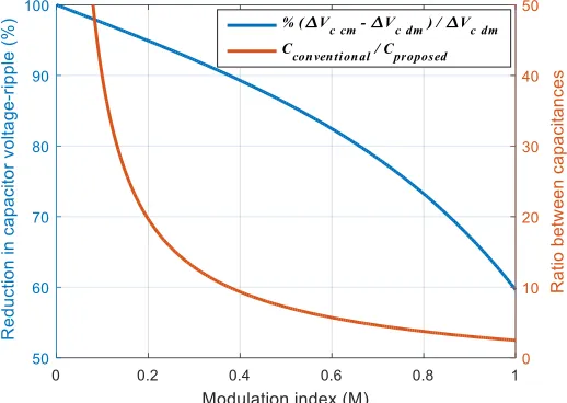
voltage fluctuation of 100 V (±2%). Further assessment of the decreased capacitor voltage-ripple is presented in Fig. 8, where the
percentage reduction in the capacitor voltage-ripple achieved by the proposed dual MMC configuration is depicted with respect to
the capacitor voltage-ripple of the conventional MMC topology, as the modulation index varies. The sizing requirement of the SM
capacitance for both topologies is also compared in Fig. 8. The percentage capacitor voltage-ripple reduction is 60% at unity
modulation index, with further improvement as the modulation index decreases. The ratio between SM capacitance, which results
in the same capacitor voltage-ripple, for a conventional MMC with respect to the proposed configuration varies between two at
unity modulation index, up to 50 times at low modulation indices. For simplicity, the reduction in the capacitor voltage-ripple
shown in Fig. 8 is calculated while considering only the DM component as the dominant voltage-ripple component for a
C. Operation at Zero Motor-Speed/frequency
In a conventional MMC topology, the unidirectional current through MMC arms during near-zero-frequency power conversion
results in a unidirectional change in SM capacitor voltage, leading to infinite capacitor voltage-ripple. In contrast, one of the salient
advantages of the proposed dual MMC configuration is that it has the capability of starting a machine at the full-load torque from
a stand-still condition with a SM capacitor ripple-free voltage profile. That is, at near zero frequency, the power drawn at the output
side will be near dc power, and therefore, the CM component of the pulsating power in MMC arms will be zero. Also, with
unidirectional transfer of the dc DM power component between each front-to-front SM in both the upper and lower arms, the
resultant pulsating power in different arms will be zero. In this case, the capacitive energy stored in the MMC arms will be
redistributed evenly at a constant level among all SMs, resulting in a constant voltage across SMs’ capacitors.
(a) (b)
Fig. 7 Idealized waveforms of capacitor voltage-variation for SMs in upper and lower arms. (C = 3 mF, f = 25 Hz, 𝑉𝑐= 2.5 kV, 𝐼𝑜= 500 A, M = 0.75, and ∅ =
[image:13.612.180.439.486.670.2]25⁰) (a) Conventional MMC topology and (b) Proposed dual MMC configuration.
D. DHB Design Guidelines
1. Transformer Leakage Inductance
Referring to (15), transformer power-transferred is governed by the phase-shift angle and transformer leakage inductance when the DHB’s switching frequency is constant. The maximum power transfer occurs when the phase-shift angle 𝜎 = ½𝜋. Therefore,
the maximum power transfer is:
𝑃𝑇𝑚𝑎𝑥=
𝑉𝑐2
32𝑓ℎ𝐿
(18)
Since the DM component of the arm power alternates as shown in (8b), the maximum amplitude of the decoupled DM power
component for each front-to-front SM is:
𝑃𝑑𝑚𝑆𝑀 =
𝑉𝑑𝑐 𝐼𝑜
4𝑁 (19)
The peak decoupled power of each adjacent SMs pair must be less than the maximum power-transfer ability of the transformer.
Substituting 𝑃𝑑𝑚𝑆𝑀 ≤ 𝑃𝑇𝑚𝑎𝑥 gives a boundary condition for the transformer leakage inductance:
𝐿 ≤ 𝑉𝑑𝑐
8𝑁𝐼𝑜𝑓ℎ
(20)
2. Ratings of the Transformer
The voltage applied on both transformer windings is ½𝑉𝑐, while the maximum transformer current is related to the peak value of
the decoupled DM power, where it is limited to half the amplitude of the output current, and is given by:
𝐼𝑇𝑚𝑎𝑥=
2𝑃𝑑𝑚𝑆𝑀
𝑉𝑐
= ½𝐼𝑜 (21)
3. Ratings of Switching Devices
The voltage rating of the DHB switching devices is 𝑉𝑐, while the current rating is ½𝐼𝑜.
IV. SIMULATION VERIFICATION
The effectiveness of the proposed dual MMC configuration with DHB energy balancing modules is verified through simulation
studies at different operating conditions. A 10 MW MATLAB/SIMULINK model is used to investigate the steady-state operation
of the proposed dual MMC configuration with a brief comparison to the traditional single-sided MMC topology, while a 100 MW
model is considered to investigate the dynamic performance of the proposed configuration when the operating frequency is
increased from zero up to the rated frequency, at rated current. Simulation parameters for both models are listed in Table I, while
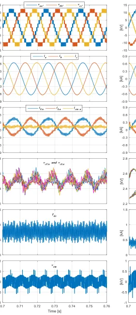
Fig. 9 Fundamental simulation waveforms for a steady-state operation of the proposed dual MMC configuration at 50 Hz.
[image:15.612.318.553.48.692.2]TABLEI SIMULATION PARAMETERS
Parameters of proposed MMC configuration
Number of SMs per arm N = 5 Input dc voltage 𝑉𝑑𝑐=12.5 kV
Average voltage across SM capacitor 𝑉𝑐=2.5 kV
Rated output voltage 8 kV
Fundamental output frequency 𝑓𝑜= 50 Hz
Carrier frequency of MMC 𝑓𝑐=2 kHz
Switching frequency of DHB 𝑓ℎ=10 kHz
Parameters for steady state operation using RL load
Rated active power 10 MW
Rated current magnitude 𝐼𝑜= 655 A
Load resistance 15.5*𝑓𝑜
50 Ω
Load inductance 24 mH
Total arm inductance per leg 2 mH Equivalent SM series capacitance 1 mF
Parameters for transient operation using an open-end winding motor
Rated active power 100 MW
Number of poles 10
Rated motor speed 600 rpm
Rated phase voltage 8 kV
Total arm inductance per leg 2.4 mH Equivalent SM series capacitance 2 mF
A. Simulation Results with an RL Load
Figs. 9 and 10 show the fundamental waveforms of 10 MW steady-state operation for both proposed and traditional MMC
configurations at both rated output current and frequency in Table I. In Fig. 9, the proposed dual MMC configuration feeds
three-phase RL load connected in an open-end configuration via three-paralleled dual-legs, each with 5 SMs per arm, supplied from a 12.5 kV dc input voltage. In Fig. 10, the traditional MMC feeds a three-phase star-connected RL load via three conventional single-legs, each of 10 SMs per arm, supplied from a 25 kV dc input voltage. For both configurations, the modulation index is set to 0.904
to generate an 8 kV output phase-voltage (13.8 kV line-to-line voltage for the single-sided configuration). Comparing the results
in Figs. 9 and 10, the differential output voltage across the terminals of the open-end load, 𝑣𝑗𝑗′, in the dual-sided configuration has
half the number of voltage levels compared to the phase voltage, 𝑣𝑗𝑜, of the single-sided topology. Nonetheless, the quality of the
output currents for both configurations are near the same, with a current peak equal to the rated value of 655 A. In both
configurations, the currents in upper and lower arms are controlled to suppress both second- and fourth-order harmonic components
to give a nearly-constant CM current as assumed in the mathematical analysis in Section II. The recorded peak arm currents is 510
A, while the average CM current is 135 A for both configurations. The capacitor voltage-ripple of the proposed dual MMC
[image:16.612.181.432.63.402.2]of 1 mF. Whereas the capacitor voltage-ripple in the traditional MMC alternates at the fundamental frequency as a consequence of
the contribution of both CM and DM ripple components. The peak-to-peak voltage-ripple of the traditional MMC is ±7.8%, while
the SM capacitance is 2 mF. The current drawn from the input supply, 𝐼𝑑𝑐, is doubled in the dual-sided topology compared to the
single-sided topology since the former operates at half the dc input voltage. The CMV of the dual-sided topology is shown to be
slightly lower than that of the single-sided topology due to the exploitation of the available redundant states offered by dual-sided
configurations.
Fig. 11 shows the voltage across each side of the HF transformer along with the transformer current during positive and negative
half cycles of the output current. The voltage across both sides is near 1.25 kV which is half the nominal SM capacitor voltage. In
Fig. 11a, the voltage at the primary side is higher than the voltage at the secondary side with a leading phase-shift, where the
waveforms are recorded during an arm current direction charging the capacitors connected to the primary side, while discharging
the capacitors connected to the secondary side, resulting in a forward power transfer from the primary to the secondary side. The
opposite case is shown in Fig. 11b, where the primary voltage lags with a lower magnitude than the secondary voltage, producing
a reverse power transfer, from the secondary to the primary side.
Fig. 12 shows the performance of the proposed dual MMC configuration when operated at low frequencies according to a
Volt/Hertz control scheme. From left to right, the results of Fig. 12 are obtained for continuous operation at 10 Hz, 5 Hz, and 1
Hz, respectively. In this case study, the output voltage is reduced in accordance to the operating frequency reduction, while the
load resistance is varied linearly with the operating frequency to maintain the output current constant at the rated value, at all
frequencies, to emulate the constant torque characteristic of variable-speed motors. The output currents are high-quality sinusoidal
waveforms with a peak of 655A, while the arm currents are maintained free of dominant even-harmonic components. Importantly,
the SM capacitor voltages are balanced and not affected by the reduction in both modulation index and operating frequency. The
peak-to-peak voltage-ripple across the SMs’ capacitors are ±5%, while the equivalent SM capacitance is 1 mF.
To assess the reduction in capacitor ripple achieved by the proposed configuration, Fig. 13 shows capacitor
voltage-variation with the deactivation of the DHB switching signals at the mid-period of a simulation at low operating frequencies. When
the DHB PWM signals are inhibited, the configuration is reduced to a conventional dual-sided MMC which inherits the same
capacitor voltage-ripple profile as the single-sided MMC. At the time of deactivation of the energy-balancing modules, the
capacitor voltage-ripple significantly increases especially as the operating frequency is further reduced. While the voltage-ripple of the SMs’ capacitors is near constant at 5% at the three-different frequencies when the DHB modules are in operation, the voltage
ripple after DHB deactivation is recorded at 33%, 50%, and 66% at 10 Hz, 5 Hz, and 1 Hz, respectively. Although the latter
voltage-ripple percentages are impractical, they highlight the significant reduction in capacitive storage-element sizing achievable
(a) (b)
Fig. 11 Key waveforms of the phase-shift DHB converter. (a) Primary voltage is leading and (b) Primary voltage is lagging.
[image:18.612.55.562.194.622.2](a) (b) (c)
Fig. 12 Simulation results for a continuous operation of the proposed dual MMC topology, at (a) 10 Hz, (b) 5 Hz, and (c) 1 Hz.
(a) (b) (c)
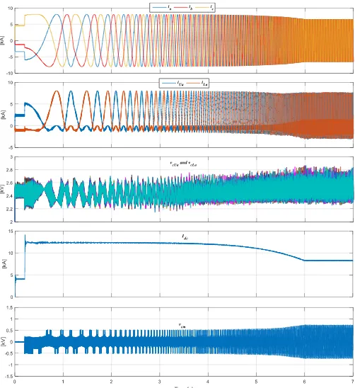
[image:18.612.55.562.621.712.2]Fig. 14 Simulation of transient operation of the proposed dual MMC configuration when driving an open-end stator winding motor from stand-still to the rated speed at constant full-load torque.
B. Simulation Results with an Open-End Winding Machine
To investigate the dynamic performance of the proposed dual MMC configuration and to establish its ability to extend the output
power to scores of megawatts, Fig. 14 presents the dynamic performance of a 100 MW, 8kV open-end winding motor, where the
high-quality over the whole speed range, while the SM capacitor voltages are balanced with a bounded voltage-ripple regardless
of the operating frequency. The dual MMC configuration is able to operate at near zero frequency with a constant SM capacitor
voltage-ripple profile. It is worth noting that the capacitor voltage-ripple is slightly increasing at frequencies near rated frequency
compared to the voltage ripple at low frequencies, where the peak-to-peak voltage-ripple varies between ±1% at near 0 Hz and
±10% at 50 Hz. The increase in the capacitor voltage-ripple at higher motor speeds is due to the growth of the CM current which
in turn increases the CM voltage-ripple component.
V. EXPERIMENTAL VERIFICATION
A scaled-down prototype of the proposed dual MMC configuration with DHB energy-balancing modules is built to practically
verify the effectiveness of the proposed concept. The experimental prototype has 3 SMs per arm (12 SMs for each dual leg), rated
at 4 kW and 210 V. The dc-link voltage is 300 V, and the nominal SM capacitor voltage is 100 V. Each front-to-front SMs are
interfaced through a DHB converter employing a nanocrystalline core-based HF transformer with a saturation flux density of 1.2
T and a unity turns ratio. The control system is implemented in a TMS320F28335 DSP. The main units employed in the
experimental setup are shown in Fig. 15, while the parameters and operating conditions are listed in Table II. Three-phase RL loads, connected in an open-end configuration, were connected to the MMC to assess converter steady-state performance at
different operating frequencies starting from the rated frequency down to 1 Hz, while the load resistance was varied linearly with
output frequency to emulate the constant torque condition of an induction motor. Results were recorded during both activation and
deactivation of the DHB modules to confirm the influence of the proposed configuration. Experimental waveforms are presented
in Figs. 16-22.
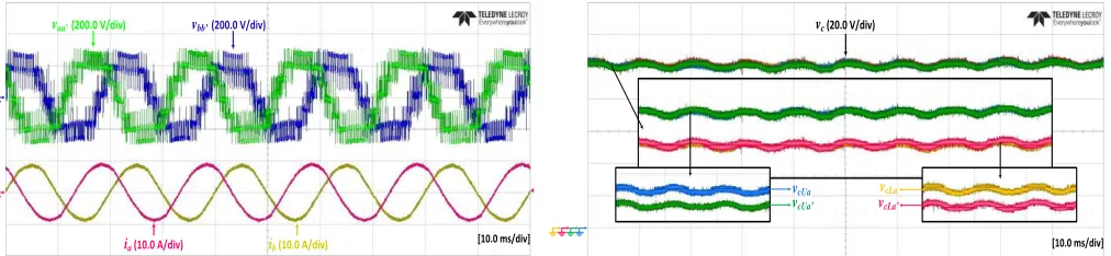
Fig. 16 shows the differential voltages across two phases of the open-end load terminals (𝑣𝑎𝑎′ and 𝑣𝑏𝑏′) and their currents (𝑖𝑎
and 𝑖𝑏) when the proposed MMC configuration is operated at 50 Hz and 0.9 modulation index. The output voltages have three
voltage-levels with a peak of the dc input voltage, while the output currents are high-quality with a magnitude of 9.5 A. Since the
three-phase configuration is balanced, the differential voltage 𝑣𝑐𝑐′ and the load current 𝑖𝑐 will have ⅔𝜋 phase displacement. Fig.
17 shows different SM capacitor voltages in the four arms of the dual phase-leg 𝑎𝑎′ where they are balanced around 100 V, while
alternating at twice the line frequency due to the CM component of the capacitor voltage-ripple.
The fundamental switching waveforms of the phase-shift DHB converter in Fig. 18, show the voltages across both transformer
sides and the transformer current during both forward and reverse power flow. The DHB converter is operating at 10 kHz, while
an auxiliary inductance of 100 µH is connected in series with the transformer primary-side. Both primary- and secondary-side
voltages are square waveforms with a constant duty cycle of 50% and near 50 V peak, which is half the nominal voltage across
TABLEII EXPERIMENTAL PARAMETERS
Number of SMs per arm N = 3
Rated active power 4 kW
Input dc voltage 𝑉𝑑𝑐= 300 V
Rated current magnitude 𝐼𝑜= 9.5 A
Average voltage across SM capacitor 𝑉𝑐= 100 V
Fundamental output frequency 𝑓𝑜= 50 Hz
Carrier frequency of MMC 𝑓𝑐= 2 kHz
Switching frequency of DHB 𝑓ℎ=10 kHz
Load resistance 30*𝑓𝑜
50 Ω
Load inductance 20 mH
Total arm inductance per leg 2.8 mH Equivalent SM series capacitance 1.1 mF Transformer turns ratio n = 1 Auxiliary leakage inductance 100 µH
Fig. 15 Scaled-down experimental setup.
[image:21.612.60.566.554.671.2]Fig. 16 Voltage and current waveforms for a steady-state operation of the proposed dual MMC configuration at 50 Hz.
Fig. 17 Voltages across SM capacitors of the same dual-leg at 50 Hz. scope
eZdsp F28335
voltage transducers SMs capacitors
DC input voltage source
RL load
gate-drive arm inductors
current transducers
circuits
DHB 3 SMs arm
dead-time circuits
differential scope-probe
power supplies
CANcaseXL device scope
vaaʽ(200.0 V/div) vbbʽ (200.0 V/div)
ia (10.0 A/div) ib (10.0 A/div) [10.0 ms/div]
vc (20.0 V/div)
[10.0 ms/div]
vcUa
vcUa
vcLa
(a) (b)
Fig.18 Fundamental switching waveforms of the phase-shift DHB converter. (a) Forward power flow and (b) Reverse power flow.
The experimental results of the dual MMC configuration that assess the SM capacitor voltage-ripple at different operating
frequencies are presented in Figs. 19-22 with suffix “a” when the DHB modules are deactivated, while suffix “b” means the DHB
modules are operational. Only the voltage of one SM from each arm is shown, since the other waveforms are virtually identical,
in addition to the output current, arm currents, and the CM current. The output voltage is reduced in accordance to operating
frequency reduction, while the load resistance is varied linearly with the operating frequency to maintain constant rated output
current. When the DHB modules are deactivated in the proposed MMC configuration, it exhibits the performance of the traditional
MMC.
At 50 Hz, Fig. 19 shows that the capacitor voltage-ripple of a traditional MMC is 14 V (±7%), while it is reduced to 7 V (±3.5%)
when the DHB modules are activated. In both cases, the output current is regulated at the rated output value, while the CM current
includes second-order harmonics, since the CM current has not been controlled to experimentally suppress even-order harmonics,
so clearly affects both arm current waveforms. In Fig. 20, the operating frequency is reduced to 10 Hz where the capacitor voltage-
ripple is 23 V (±11.5%) for a traditional MMC, and 11 V (±5.5%) with DHB activation. With further operating frequency reduction
to 5 Hz (Fig. 21) and 1 Hz (Fig. 22), the capacitor voltage-ripple is significantly increased to 42 V (±21%) and 115 V (±57.5%),
respectively, for a traditional MMC topology, while being 14 V (±7%) and 18 V (±9%), respectively, with DHB modules operation.
As the operating frequency is reduced, the output current of the traditional MMC can no longer be controlled at the rated value,
since the increased capacitor voltage-ripple results in a loss of controllability. In contrast, the output current of the proposed MMC
configuration is always regulated at the rated value, regardless of the operating frequency, as shown in Figs. 19-22. The quality of
the load current waveforms is adversely affected with the operating frequency reduction since the number of voltage levels is
reduced. The percentage reduction in the capacitor voltage-ripple, and hence the reduction in the required capacitance, gained by
the activation of the DHB modules, is found to be 66% and 84% at 5 Hz and 1 Hz, respectively, although the output currents are
much lower than the rated value when the DHB modules are deactivated at these low operating frequencies.
vp (20.0 V/div) vs (20.0 V/div)
iT (10.0 A/div)
[50.0 µ s/div]
vp (20.0 V/div) vs (20.0 V/div)
iT (10.0 A/div)
(a) (b) Fig. 19 Experimental results at 50 Hz when DHB modules are (a) deactivated and (b) activated.
[image:23.612.46.564.207.332.2](a) (b)
Fig. 20 Experimental results at 10 Hz when DHB modules are (a) deactivated and (b) activated.
(a) (b)
Fig. 21 Experimental results at 5 Hz when DHB modules are (a) deactivated and (b) activated.
(a) (b)
Fig. 22 Experimental results at 1 Hz when DHB modules are (a) deactivated (b) activated. [10.0 ms/div]
vcUa(20.0 V/div) vcLa (20.0 V/div)
iLa (10.0 A/div) iUa (10.0 A/div)
icm a (10.0 A/div)
ia (10.0 A/div)
14 V
[10.0 ms/div]
vcUa(20.0 V/div) vcLa (20.0 V/div)
iLa (10.0 A/div) iUa (10.0 A/div)
icm a (10.0 A/div)
ia (10.0 A/div)
7 V
[50.0 ms/div]
vcUa(20.0 V/div) vcLa (20.0 V/div)
iLa (10.0 A/div) iUa (10.0 A/div)
icm a (10.0 A/div)
ia (10.0 A/div)
23 V
[50.0 ms/div]
vcUa(20.0 V/div) vcLa (20.0 V/div)
iLa (10.0 A/div) iUa (10.0 A/div)
icm a (10.0 A/div)
ia (10.0 A/div)
11 V
[100.0 ms/div]
vcUa (20.0 V/div) vcLa (20.0 V/div)
iLa (10.0 A/div) iUa (10.0 A/div)
icm a (10.0 A/div)
ia (10.0 A/div)
42 V
[100.0 ms/div]
vcUa(20.0 V/div) vcLa (20.0 V/div)
iLa (10.0 A/div) iUa (10.0 A/div)
icm a (10.0 A/div)
ia (10.0 A/div)
14 V
[500.0 ms/div]
vcUa vcLa
iLa (10.0 A/div) iUa (10.0 A/div)
icm a (10.0 A/div)
ia (10.0 A/div)
115 V
(50.0 V/div) (50.0 V/div)
[500.0 ms/div]
vcUa(20.0 V/div) vcLa (20.0 V/div)
iLa (10.0 A/div) iUa (10.0 A/div)
icm a (10.0 A/div)
ia (10.0 A/div)
[image:23.612.54.562.363.488.2] [image:23.612.40.562.518.642.2]VI. ASSESSMENT OF PROPOSED MMC CONFIGURATION
Compared with the currently-accepted MMC topologies and circulating-current control approaches, the proposed dual MMC
configuration is characterized as an innovative solution able to drive MV multi-megawatt open-end winding machines at full-load
torque, in an independent scheme of the operating frequency, even at zero speed/frequency. The proposed configuration inserts
DHB modules, between each front-to-front SM of the same dual-leg, that form an auxiliary branch for the dual MMC topology to
maintain the SM capacitor voltage-balance over whole frequency range. Therefore, the proposed configuration has a power branch
and an auxiliary balance branch, with the former to perform the necessary power conversion, while the latter to decouple the
fundamental ripple-power component to maintain voltage balance between the SMs. It is worth mentioning that the proposed
configuration still retains the modularity feature since the auxiliary balance branches have a modular scheme. In addition, there is
no interaction between the control of the DHB modules and the basic control loops of the MMC.
The decoupling of the fundamental ripple-power component between front-to-front SMs through the DHB modules results in a
reduction in SM capacitance. The DHB hardware adds volume to the MMC system, countering the capacitance reduction. Aside
from the two added switching devices for each MMC SM, the inserted transformer between front-to-front SMs is an energy transfer
element, and does not increase MMC stored energy. Thus, the DHB with the reduced SM capacitance reduces system stored
energy.
The proposed MMC configuration has a dc-fault blocking capability. With the inhibition of the PWM signals of the switching
devices at the fault instant, the proposed configuration produces a zero differential voltage across the machine windings, while the
SM capacitors do not contribute to the dc-fault current.
Considering the efficiency of the proposed MMC configuration, the four switching devices and the HF transformer inevitably
increase the power loss and reduce the efficiency of the overall system when compared to a conventional MMC topology. However,
since conventional MMC topologies cannot drive multi-megawatt machines at very low speeds, accurate power loss analysis will
be investigated in future research to compare the efficiency of the proposed MMC configuration with the efficiency of MMC
topologies that utilize HF circulating-current injection approaches.
A comparison of the proposed MMC configuration with the conventional MMC topology in terms of component volume is
presented for 10 MW system selected as the case study. Since the number of SMs is the same, and identical, the comparison is
conducted for only one SM.
A. Switching Devices
For the power branch, the 5SNA1200G450350 IGBT with 4.5 kV, 1200 A power rating is chosen [57], while the balancing
balancing-branch IGBTs is 1.28 L and 0.87 L respectively. For conventional MMC topology, two power-branch IGBTs are
required, while the proposed MMC configuration requires two balancing-branch IGBTs in addition to the conventional two
power-branch IGBTs. As a result, the volume of the switching devices is increased by 68%.
B. SM Capacitors
Each SM in the proposed MMC configuration requires two 2 mF and 1.4 kV capacitors. This capacitance enables the proposed
MMC configuration to operate the 10 MW system continuously at any operating frequency, even at near zero frequency, with a
near constant ±5% capacitor voltage-ripple. To achieve the same voltage-ripple suppression effect, according to the simulation
results in Fig. 13c at 1 Hz, the capacitance of the conventional MMC topology should be 13 times that of the equivalent SM
capacitance of the proposed MMC configuration. Therefore, the conventional MMC topology requires one capacitor with 13 mF
and 2.8 kV, while being unable to drive such 10 MW system at near zero frequency. The capacitive energy stored in each SM in
case of the conventional MMC topology is 51 kJ, while it is only 4 kJ for the proposed MMC configuration. Accordingly, the
percentage reduction in the capacitive stored-energy achieved by the proposed MMC configuration is 92%. To assess the reduction
in the capacitors size, according to the oil-impregnated power capacitors from EPOCS [59], the volume of capacitors combination
required to match the parameters of the SM capacitor of a conventional MMC is 440 L, while the volume of the SM split-capacitor
for the proposed MMC configuration is only 38 L, with a 91% volume reduction.
C. HF Transformer
For a full decoupling of the fundamental ripple-power component, each front-to-front SM requires a HF transformer with 1:1
turns ratio and 1.25 kV, 330 A power rating. An estimation for the transformer size can be obtained based on practical assemblies
for HF transformers designed for high-power applications in previous studies [60]-[62], where the transformer volume for the
[image:25.612.155.445.535.726.2]mentioned ratings could be 17 L.
Fig. 23 compares the volume of the main components of each SM for both MMC approaches. By using the proposed MMC
configuration, the component volume can be reduced from 445 L to 55 L, resulting in 87% reduction in the overall SM volume. It
should be noted that this is only a comparison for the volume of the main SM components (capacitor, HF transformer, IGBT, and
heatsink), rather than a comparison of the volume of real SM enclosures (in which there are more components). Nevertheless, a
significant decrease in the main component volume enables a more compact and lighter layout design of an SM enclosure.
VII. CONCLUSION
A novel configuration for MV high-power machine drives incorporating open-end stator windings has been proposed based on
a dual MMC topology. The configuration is characterized by the insertion of HF transformer-based bidirectional dc-dc converter
modules between to-front SMs operating in the same dual-leg. Based on the fact that the fundamental ripple-power of
front-to-front SMs in dual MMC topology alternates with an opposite phase, the dc-dc converter modules can decouple this fundamental
ripple-power, allowing the capacitive stored-energy to be evenly distributed among all SMs. The main advantages of the proposed
configuration are summarized as follows. It offers i) a significant reduction in SM capacitance since the voltage fluctuations across
the capacitors are brought down to a very narrow band, therefore reducing the energy stored in the converter system. ii) eliminates
the problems of capacitor-voltage fluctuations in an independent operating frequency scheme. iii) a single dc-source operation with
half the value of the dc input voltage compared to single-sided converter configurations, in addition to the higher redundant space
vector combinations that are utilized in CMV elimination. iv) a dc-fault blocking capability. v) compared to circulating-current
injection methods, the proposed configuration does not affect the arm current or the CMV. The proposed configuration is believed
to be the most suitable solution for adjustable-speed drives since it guarantees the continuous operation at any speed/torque
condition with the ability of driving multi-megawatt machines from stand-still at full-load torque.
Minor drawbacks countering the mentioned advantages are i) the proposed configuration utilizes extra hardware which slightly
reduces the MMC system efficiency. ii) it necessitates each MMC SM to have a split capacitor bank. iii) it is restricted to machines
with an open-end winding connection.
The proposed configuration has been examined for MV high-power adjustable-speed drive applications through mathematical
analysis and simulations. Theoretical deductions were validated by experimentation, which agreed with theoretical analysis and
simulation.
REFERENCES
[1] A. Lesnicar and R. Marquardt, “An innovative modular multilevel converter topology suitable for a wide power range,” in Proc. IEEE Power Tech. Conf., Bologna, Italy, vol. 3, Jun. 23–26, 2003.
[3] S. Debnath, J. Qin, B. Bahrani, M. Saeedifard, and P. Barbosa, “Operation, control, and applications of the modular multilevel converter: a review,” IEEE
Trans. Power Electron., vol. 30, no. 1, pp. 37–53, Jan. 2015.
[4] H. Akagi, “Classification, terminology, and application of the Modular Multilevel Cascade Converter (MMCC),” IEEE Trans. Power Electron., vol. 26, no. 11, pp. 3119–3130, Nov. 2011.
[5] L. Harnefors, A. Antonopoulos, S. Norrga, L. Angquist, and H.-P. Nee, “Dynamic analysis of modular multilevel converters,” IEEE Trans. Ind. Electron., vol. 60, no. 7, pp. 2526–2537, Jul. 2013.
[6] M. Saeedifard and R. Iravani, “Dynamic performance of a modular multilevel back-to-back HVDC system,” IEEE Trans. Power Del., vol. 25, no. 4, pp. 2903–2912, Oct. 2010.
[7] M. Guan and Z. Xu, “Modeling and control of a modular multilevel converter-based HVDC system under unbalanced grid conditions,” IEEE Trans. Power
Electron., vol. 27, no. 12, pp. 4858–4867, Dec. 2012.
[8] A. Hassanpoor, A. Roostaei, S. Norrga, M. Lindgren, “Optimization- Based Cell Selection Method for Grid-Connected Modular Multilevel Converters,”
IEEE Trans. Power Electron., vol. 31, no. 4, pp. 2780 - 2790, April. 2016.
[9] J. Peralta, H. Saad, S. Dennetiere, J. Mahseredjian, and S. Nguefeu, “Detailed and averaged models for a 401-level MMC–HVDC system,” IEEE Trans.
Power Del., vol. 27, no. 3, pp. 1501–1508, Jul. 2012.
[10] M. Hagiwara, K. Nishimura, H. Akagi. “A Medium-Voltage Motor Drive with a Modular Multilevel PWM Inverter,” IEEE Trans. Power Electron., vol. 25, no. 7, pp. 1786-1799, 2010.
[11] S. Busquets-Monge, S. Somavilla, J. Bordonau, and D. Boroyevich, “Capacitor voltage balance for the neutral-point-clamped converter using the virtual space vector concept with optimized spectral performance,” IEEE Trans. Power Electron., vol. 22, no. 4, pp. 1128–1135, Jul. 2007.
[12] S. Thielemans, A. Ruderman, B. Reznikov, and J. Melkebeek, “Improved natural balancing with modified phase-shifted PWM for single-leg five-level flying-capacitor converters,” IEEE Trans. Power Electron., vol. 27, no. 4, pp. 1658–1667, Apr. 2012.
[13] S. Du, J. Liu, and J. Lin, “Hybrid cascaded h-bridge converter for harmonic current compensation,” IEEE Trans. Power Electron., vol. 28, no. 5, pp. 2170– 2179, May 2013.
[14] A. Korn, M. Winkelnkemper, and P. Steimer, “Low output frequency operation of the modular multi-level converter”, in Proc. IEEE ECCE, 2010, pp. 3993– 3997.
[15] S. Debnath, J. Qin and M. Saeedifard, “Control and Stability Analysis of Modular Multilevel Converter Under Low-Frequency Operation,” IEEE Trans. Ind.
Electron, vol. 62, no. 9, pp. 5329-5339, Sept. 2015.
[16] J. Kolb, F. Kammerer, M. Gommeringer, and M. Braun, “Cascaded control system of the modular multilevel converter for feeding variable-speed drives,”
IEEE Trans. Power Electron., vol. 30, no. 1, pp. 349–357, Jan. 2015.
[17] M. Spichartz, V. Staudt, A. Steimel, “Modular multilevel converter for propulsion system of electric ships”, in IEEE Electric Ship Technologies Symposium
(ESTS), 2013, pp. 237–242.
[18] A. Antonopoulos, L. Angquist, S. Norrga, K. Ilves, L. Harnefors, H.-P. Nee, “Modular multilevel converter ac motor drives with constant torque from zero to nominal speed,” IEEE Trans. Ind. Appl., vol. 50, no. 3, pp. 1982–1993, May/Jun. 2014.
[19] J. Jung, H. Lee, and S. Sul, “Control of the modular multilevel converter for variable-speed drives,” in Proc. IEEE International Conference on Power
Electronics, Drives and Energy Systems, 16-19, Bengaluru, India, Dec. 2012, pp. 1–6.
[20] K. Wang, Y. Li, Z. Zheng, and L. Xu, “Voltage balancing and fluctuation-suppression method of floating capacitors in a new modular multilevel converter,”
IEEE Trans. Ind. Electron., vol. 60, no. 5, pp. 1943–1954, May 2013.
[21] M. Hagiwara, I. Hasegawa, and H. Akagi, “Start-up and low-speed operation of an electric motor driven by a modular multilevel cascade inverter,” IEEE