This is a repository copy of
Non-invasive charge detection in
surface-acoustic-wave-defined dynamic quantum dots
.
White Rose Research Online URL for this paper:
http://eprints.whiterose.ac.uk/110853/
Version: Accepted Version
Article:
Astley, M.R., Kataoka, M., Ford, C.J.B. et al. (6 more authors) (2016) Non-invasive charge
detection in surface-acoustic-wave-defined dynamic quantum dots. Applied Physics
Letters, 109 (18). 183501. ISSN 0003-6951
https://doi.org/10.1063/1.4966667
[email protected] https://eprints.whiterose.ac.uk/
Reuse
Unless indicated otherwise, fulltext items are protected by copyright with all rights reserved. The copyright exception in section 29 of the Copyright, Designs and Patents Act 1988 allows the making of a single copy solely for the purpose of non-commercial research or private study within the limits of fair dealing. The publisher or other rights-holder may allow further reproduction and re-use of this version - refer to the White Rose Research Online record for this item. Where records identify the publisher as the copyright holder, users can verify any specific terms of use on the publisher’s website.
Takedown
If you consider content in White Rose Research Online to be in breach of UK law, please notify us by
M. R. Astley,∗† M. Kataoka, C. J. B. Ford, C. H. W. Barnes,
D. Anderson, G. A. C. Jones, I. Farrer, D. A. Ritchie, and M. Pepper†
Cavendish Laboratory, University of Cambridge, J. J. Thomson Ave., Cambridge CB3 0HE, United Kingdom.
Using a non-invasive charge detection method, we detect a flow of electrons trapped in dynamic quantum dots. The dynamic quantum dots are defined by surface acoustic waves (SAWs) and move through a long depleted one-dimensional channel. A one-dimensional constriction is placed next to the SAW channel but in a separate circuit; the current induced by the SAWs through this detector constriction is sensitive to the number of electrons trapped in the SAW mnima. We observe steps in the detector acoustoelectric current as the number of electrons carried by SAWs are varied as
1,2,3. . ..
PACS numbers: 73.23.Hk, 73.50.Rb, 73.63.Kv
Surface acoustic waves (SAWs) can produce a quan-tised acoustoelectric current through an empty one-dimensional channel.1 Electrons are carried through the
SAW channel in dynamic quantum dots; on the acousto-electric current plateau, each dynamic quantum dot con-tains an integer number of electrons.2 The fundamental
properties of electrons confined to dynamic quantum dots in complex surface acoustic wave circuits have been the object of recent experimental3,4 and theoretical5,6
stud-ies. Also, it has been proposed that the spins of sin-gle electrons in dynamic quantum dots could be used as qubits for a quantum computer.7 However, far fewer
ex-perimental techniques have been developed for probing the characteristics of dynamic quantum dots, as com-pared to static dots.8,9 For static quantum dots, one
of the most powerful techniques is non-invasive charge detection:10 the conduction through a quantum point
contact alongside the quantum dot is affected by the charge of electrons in the dot, and this effect has been widely used to probe fundamental quantum properties of confined electrons.11–16
Here, we report our non-invasive charge detection mea-surement in SAW dynamic quantum dots. In our de-vice a detector constriction, which is sensitive to the lo-cal electric potential, is created next to a SAW channel. The potential landscape is partially determined by the electrons occupying dynamic quantum dots through the SAW channel. Therefore the current through the detec-tor constriction senses the charge in dynamic dots.ng a nearby SAW channel.
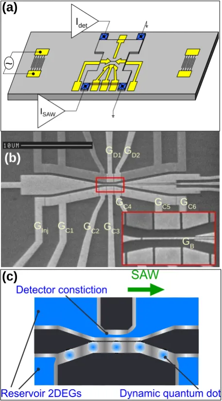
The device [shown in Figs. 1(a) and (b)] was made using a GaAs/AlGaAs heterostructure which contained a two-dimensional electron gas (2DEG) 97nm below the surface. The 2DEG had a mobility of 160 m2/Vs and a
carrier density of 1.8×10¹⁵m−2, measured at 1.5 K in
the dark. SAWs were generated by applying a resonant
∗email: [email protected]
†also affiliated with Toshiba Research Europe Ltd., Cambridge
Research Laboratory, 208 Cambridge Science Park, Cambridge CB4 0GZ, United Kingdom
microwave signal from an Agilent 8648D signal genera-tor to a transducer, made of 70 pairs of interdigitated fingers with a period of 1µm. The microwave signal was pulse-modulated using a Tektronix PG5110 pulse gener-ator with a duty ratio of 10µs : 500µs to prevent heat-ing of the sample by the SAW.17 The SAWs travelled
across the surface of the chip to the NiCr/Au surface gates shown in Fig. 1(b) which were situated 2.5 mm from the transducer. When a negative voltage was ap-plied to the surface gates, the 2DEG below the gates was depleted, creating the SAW and detector channels. +0.3 V was applied to the surface gates during cool-down to minimise random switching noise.18
The device operation is shown in Fig. 1(c): the SAW carries electrons into the normally empty SAW channel in dynamic quantum dots. The occupation of each dynamic quantum dot is controlled by the injector gate (GInj)—
as the voltage applied to the injector gate (Vinjector) is
swept the acoustoelectric current through the SAW chan-nel (ISAW) takes on quantised values of ISAW = nef
wherenis the integer occupation number of electrons in each dynamic quantum dot,eis the electron charge, and
f is the frequency of the SAW (typically ∼ 2.7 GHz).1
The electrons are carried along the channel to the cen-tral barrier region by the dynamic quantum dots (the SAW channel gate voltages GC1-GC6 have been carefully
tuned to avoid any abrupt changes in the gradient of the electric potential, which could otherwise lead to elec-trons escaping from the dynamic quantum dots19). A
sufficiently negative bias is applied to the barrier gate (GB) that no electrons can escape across the barrier
be-tween the channels.3However, the charge of the electrons
in the SAW channel will couple capacitively to the detec-tor channel constriction. Therefore the detecdetec-tor channel current can be used to monitor the occupation of the dynamic quantum dots in the top channel.
Figure 2 shows the effect of sweeping the injector gate. The SAW channel current (solid line) shows plateaux at multiples of 8.7 pA, which is ISAW = nef reduced by
the 1 : 50 pulse ratio;20 the locations of plateaux are
2
GInj GC1 GC2 GC3
GC4 GC5 GC6
GB GD1GD2
(b)
(c)
~
ISAW Idet(a)
FIG. 1: (colour online). a) Schematic of the device. b) Scan-ning electron microscope image of the device surface gates. The gates are labeled as follows: detector channel gates (GD1 and GD2), barrier gate (GB), injector gate (GInj), SAW chan-nel Gates (GC1-GC6). Dark shaded gates were not used in this experiment, and were held at a voltage of +0.3 V (i.e. undefined). c) Device operation: the electron occupation of a dynamic quantum dot is measured by observing the current flowing through the detector constriction.
channel (see below), can be seen to clearly follow the features in ISAW, despite the fact that the gate being
swept is∼8µm away from the detector circuit and would
therefore be expected to have a negligible direct coupling to the detector current. However, Idet is sensitive to
changes in the local potential landscape. The electrons which make up the acousto-electric current are carried through the channel in dynamic quantum dots, and so they are out of equilibrium with the reservoir 2DEGs. This means that the additional charge contained in the
0 20 40 60 -10 -20 -30
-0.74 -0.72 -0.70 -1 0 1 2 0 1 2 I S A W ( p A ) (a)
3ef / 50 2ef / 50
I d e t ( p A )
ef / 50
(b) d I S A W / d V i n je c t o r ( n A / V ) V injector (V) d I d e t / d V i n je c t o r ( n A / V )
FIG. 2: (colour online). a) Current produced in the SAW channel (dotted line) and detector constriction (solid line) as a function of the injector gate voltage. b) Differential of the SAW channel (dotted line) and detector constriction (solid line) currents.
dynamic quantum dots increases the local electric poten-tial, and so as the current carried in the dynamic quan-tum dots past the detector constriction is increased the constriction is closed, and the magnitude of the detector current decreases.
Note that the current through the detector circuit is negative. This is because the channel is sufficiently open for the current to be dominated by crosstalk (current generated by the interaction between the free-space elec-tromagnetic wave and the SAW), rather than being a true acoustoelectrically-pumped current—it is experimentally known that crosstalk current can be positive or negative depending on various conditions (frequency, SAW ampli-tude, gate geometry) for reasons that are not fully under-stood. The crosstalk current is more sensitive to changes in the local potential landscape than an acoustoelectric charge-pump current, and also has the advantage that it is approximately linear over tens of picoamp variation and so gives a uniform sensitivity, whereas if a charge-pump current was used in the detector circuit then the current plateau would lead to a non-linear sensitivity.
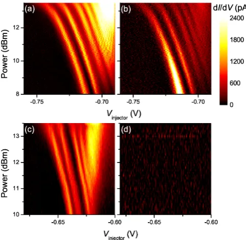
[image:3.595.325.553.50.290.2] [image:3.595.62.291.52.464.2]FIG. 3: (colour online). The differentials of the currents in the SAW and detector channels with respect to the injector gate voltage: (a) SAW channel and (b) detector constriction, where the SAW current is transported through the SAW chan-nel in dynamic quantum dots; (c) SAW chanchan-nel, and (d) de-tector constriction, where the SAW channel gate voltages have been backed off to allow an open one-dimensional channel of electrons to form in the SAW channel.
reset the detector constriction current to -10 pA at the start of each sweep, because the detector channel current is strongly sensitive to the transducer power).
To demonstrate that it is the confined non-equilibrium charge in the dynamic quantum dots rather than the mere presence of electric current that controls the de-tector channel current, the voltages applied to the SAW channel gates C2-C6were backed off so that the channel
was populated by an electron Fermi sea in the region de-fined by C2-C6. In this regime the electrons are pumped
over the constriction at the injector gate and the current flows through the open 1D channel, but the SAW will
be screened by the free electrons in the channel and so electrons are not confined to dynamic quantum dots as they pass the detector and there is no net increase in the charge close to the detector constriction. The differ-entials of the SAW channel and detector constriction are shown in Figs. 3(c) and (d). The SAW channel behaves in a similar way to as in Figs. 3(a) and (b), but the detector current does not record any features, as there is no non-equilibrium charge confined in dynamic quantum dots to change the channel current. This demonstrates that it is the non-equilibrium charge confined to dynamic quan-tum dots which creates an effect in the detector current, and not merely the fact that a current is flowing through the SAW channel.
It was hoped that the detector circuit could be cal-ibrated by applying a bias to the free electron gas in the open channel to pinch off the detector constriction;10
however the results obtained from this method proved counterintuitive—the energy levels in the dynamic quan-tum dots appeared to become more closely spaced as confinement was increased, which contradicts both theo-retical and experimental investigations in static quantum dots.8It is likely that the electronic configuration of a
se-ries of SAW-defined dynamic quantum dots is sufficiently different to that of an open one-dimensional channel that no useful comparisons can be drawn between the two.
In conclusion, we have demonstrated that a detec-tor circuit may be used to observe the occupation of a SAW-defined dynamic quantum dot. The measurement is carried out non-invasively by using the effect of the change in the local electric potential caused by the non-equilibrium charge contained in the dynamic quantum dot. This technique is expected to be widely used as in-creasingly complex SAW devices are developed, as non-invasive charge detection will be necessary both to test each component of a multiple-stage SAW circuit and to probe fundamental quantum effects in SAW devices (for example, as a “which path” detector21 in a SAW
quan-tum interferometer5).
This work was funded by the UK EPSRC. MRA thanks Toshiba for funding.
1 J. M. Shilton, V. I. Talyanskii, M. Pepper, D. A. Ritchie, J. E. F. Frost, C. J. B. Ford, C. G. Smith, and G. A. C. Jones, J. Phys.: Condens. Matter8, L531 (1996).
2 A. M. Robinson and V. I. Talyanskii, Phys. Rev. Lett.95, 247202 (2005).
3 M. R. Astley, M. Kataoka, C. J. B. Ford, C. H. W. Barnes, D. Anderson, G. A. C. Jones, I. Farrer, D. A. Ritchie, and M. Pepper, Phys. Rev. Lett.99, 156802 (2007).
4 M. Kataoka, M. R. Astley, A. L. Thorn, D. K. L. Oi, C. H. W. Barnes, C. J. B. Ford, D. Anderson, G. A. C. Jones, I. Farrer, D. A. Ritchie, et al., in preperation. 5 R. Rodriquez, D. K. L. Oi, M. Kataoka, C. H. W. Barnes,
T. Ohshima, and A. K. Ekert, Phys. Rev. B72, 085329
(2005).
6 A. L. Thorn, D. K. L. Oi, M. Kataoka, and C. H. W. Barnes, in preperation.
7 C. H. W. Barnes, J. M. Shilton, and A. N. Robinson, Phys. Rev. B62, 8410 (2000).
8 L. P. Kouwenhoven, D. G. Austing, and S. Tarucha, Re-ports On Progress In Physics64, 701 (2001).
9 L. P. Kouwenhoven and C. M. Marcus, Phys. World 11, 35 (1998).
10 M. Field, C. G. Smith, M. Pepper, D. A. Ritchie, J. E. F. Frost, G. A. C. Jones, and D. G. Hasko, Phys. Rev. Lett.
70, 1311 (1993).
[image:4.595.53.294.50.284.2]4
Y. Jin, and H. Launois, Physica E6, 457 (2000).
12 J. M. Elzerman, R. Hanson, L. H. W. van Beveren, B. Witkamp, L. M. K. Vandersypen, and L. P. Kouwen-hoven, Nature430, 431 (2004).
13 J. M. Elzerman, R. Hanson, L. H. W. van Beveren, L. M. K. Vandersypen, and L. P. Kouwenhoven, Appl. Phys. Lett.84, 4617 (2004).
14 S. Gustavsson, R. Leturcq, B. Simovic, R. Schleser, T. Ihn, P. Studerus, K. Ensslin, D. C. Driscoll, and A. C. Gossard, Phys. Rev. Lett.96, 076605 (2006).
15 T. Fujisawa, T. Hayashi, R. Tomita, and Y. Hirayama, Science312, 1634 (2006).
16 K. MacLean, S. Amasha, I. P. Radu, D. M. Zumbuhl, M. A. Kastner, M. P. Hanson, and A. C. Gossard, Phys. Rev. Lett.98, 036802 (2007).
17 R. J. Schneble, M. Kataoka, C. J. B. Ford, C. H. W.
Barnes, D. Anderson, G. A. C. Jones, I. Farrer, D. A. Ritchie, and M. Pepper, Appl. Phys. Lett. 89, 122104
(2006).
18 M. Pioro-Ladri`ere, J. H. Davies, A. R. Long, A. S. Sachra-jda, L. Gaudreau, P. Zawadzki, J. Lapointe, J. Gupta, Z. Wasilewski, and S. Studenikin, Phys. Rev. B72, 115331
(2005).
19 M. Kataoka, C. H. W. Barnes, H. E. Beere, D. A. Ritchie, and M. Pepper, Phys. Rev. B74, 085302 (2006).
20 M. Kataoka, C. J. B. Ford, C. H. W. Barnes, D. Anderson, G. A. C. Jones, H. E. Beere, D. A. Ritchie, and M. Pepper, J. Appl. Phys.100, 063710 (2006).