Abstract: In this paper the proposed efficient FIR filter architecture using a distributed arithmetic (DA) algorithm in which two issues are discussed in the conventional FIR filter. The FIR filter is well known to include delay elements, multipliers and adders. Due to the need for multipliers, this results in 2 demerits which are (i) increased in area and (ii) delayed increases that eventually lead to low efficiency (low speed). A notable feature of the proposed technique is to substitute a trivial amount of indexed LUT pages instead of conventional LUT based DA that it helps to maintain the access time lower. Also, significant idea connected with the proposed technique is required page can be thoroughly selected with the selection module without needing adders that result in reduced computation time. Furthermore, the proposed fast FIR filter is used for the powerful ECG noise elimination technique, which is prevalently used in biomedical and healthcare applications. The designs are simulated and synthesized by using Xilinx ISE. It can be seen from reports that our proposed DA consumes 30% less power for 11-tap FIR filters with a 40% shorter area, while the saving in power consumption for 8-tap FIR filters is 30% to 80% and 35% to 80% in the area. Especially in contrast with all the above-mentioned DA techniques, our enhanced quick FIR filters require less area and less power intake due to their lower memory requirements. All architectures are designed for FIR filters with 4 and 8 taps.
Index Terms: Distributed arithmetic · Multiplier-less filter; VLSI design; FIR filter; LUT; ECG noise removal.
I. INTRODUCTION
Recently, numerous audio and image signal processing has been evolved with the improvement in VLSI technology. The FIR (Finite Impulse Response) filter has several applications in digital signal processing, particularly suitable for eliminating PLI (Power Line Interference) [1]. Throughout this mechanism, the obtained ECG data is first digitized and forwarded to the signal preprocessing stage of the filtering unit. The filter unit minimizes noise from two stage FIR filters, for instance, the baseline walking, power line interference and high-frequency noise. Several techniques [3-10] were used to boost the output and make the filter area power efficient. The most profitable technique was distributed arithmetic (DA) [2]. It contributes to the framework of the multiplier-less structure and tends to make the system area performance environmentally friendly. Several of these applications are computationally intensive, with prevalent operations being multiplication and/or addition. The main benefit of the distributed arithmetic
Revised Manuscript Received on July 22, 2019.
Ch. Pratyusha Chowdari, Research Scholar in GITAM and Working as Assistant Professor, Department of ECE, GRIET, Hyderabad, Telangana, India.
Dr. J. B. Seventline, Professor, Department of ECE, GITAM, Andhra
strategy is that the multiplication process is accelerated by pre-computing all necessary medium values and storing them in a ROM. We could also use the input data to resolve the memory and the outcome directly. Distributed decomposition of arithmetic and row-column reduces hardware volume and improves speed performance. However, in some cases especially, the main difficulty with DA is that the need for memory/LUT capacities increases with the filter order exponentially, since DA implementations need 2K–words (K
being the number of filter taps). This represents a first obstacle for high-quality FIR filters. In [11], the authors proposed a flexible architecture that would progressively replace multiplexer/adder pairs with LUT needs. The authors take advantage that block values in a LUT-DA structure corresponding to K coefficients are equivalent to block values corresponding to K+1 coefficients if the latter coefficient is rejected. In this paper, a single large conventional LUT based DA is switched by a number of smaller indexed LUT pages to reduce the exponential increase and decrease of the system access time.
Selection module from the intended page selects the required value and feeds the value with further calculation. The tradeoff between LUTs' access times and perhaps the selection module responsible for achieving critical path to minimal for maximizing operating speed. We reveal that our modified version is superior to previous LUT-very miniature DA architectures in terms of area. Finally, we used a Distributed Arithmetic FIR filter method based on FPGA to erase the noise from the ECG signal using the Xilinx Design Suite. It is a high-level software tool that allows Matlab to create and verify Xilinx FPGAs ' hardware designs
The main contributions and organization of this paper are summarized as follows: In section 2 we describe background details of DA and FIR filter details. Section 3 proposed work. Section 4 deliberates results and discussions. Finally, in section 5, we concluded the paper.
II. BACKGROUND WORKS
A. Overview of DA based FIR Filter
The essential activities of the FIR filter require multiplying the filter coefficients and repeated accumulation of the input digital data. The multiplier and adders are the two main electricity consuming blocks in VLSI signal processing. The researchers, therefore, focused on multiplying fewer FIR filter designs. The researchers, therefore, concentrated on multiplying less FIR filter design. The traditional multipliers are therefore fully replaced by shifting and adder circuits. Distributed arithmetic (DA)
can be used to calculate product sums. Many DSP algorithms are formulated in
An Efficient FIR Filter Architecture
Implementation using Distributed Arithmetic
(DA) for DSP Applications
the sum of products (SOP) form, such as convolution and correlation. Take into account the proceeding product sum:
1
, 0 0 1 1 1 1
0 N
y c x c n x n c x c x c N x N
n
K (1)
Further assume that the coefficients c[n] are known values and that the variable x[n] can be represented by
1
2 0
B b
x n xb n
b
withxb
n , (2) Where xb
n represents the bth bit position of the number’s binary representation. The SOP can be represented as:
1 1
, 2
0 0
N B b
y c x c n xb n
n b
(3)
Expanding the summations yields to:
1
2
0
, 0 1 0 2B 2 0 2B 0 0 2
y c x c xB xB Kx
1
2
0
1 1 1 2B 2 1 2B 0 1 2
c xB xB x
K
…
1
2
0
1 1 1 2B 2 1 2B 0 1 2
c N xB N xB N x N
K (4)
Redistributing the terms we have:
1, 0 1 0 1 1 1 1 1 1 2B
y c x c xB c xB Kc N xB N
2
0 2 0 1 2 1 1 2 1 2
0
0 0 0 1 0 1 1 0 1 2
B
c xB c xB c N xB N
c x c x c N x N
K M K (5)
In more compact form:
1 1
, 2
0 0
B bN
y c x c n x n
b n b
(6) Finally, a block diagram for the DA implementation of an FIR filter is shown in figure 1.
X0[N-1]
. . . XB-1[N-1] X1[N-1]
X0[1]
. . . XB-1[1] X1[1]
X0[0]
. . . XB-1[0] X1[0]
. . . . . . . . .
L
U
T
+/-R
e
g
is
te
r
[image:2.595.308.549.475.599.2]Bit shift register Arith. Table Scaling Accumulator
Fig.1: DA Block Diagram
B. FIR filter implementation using Different DA techniques
As mentioned above, the primary issue with LUT-based. The main problem with LUT-based implementation is, as stated above, that the LUT prerequisite grows exponentially with the filter order. The main strategy for addressing this problem is using the 4-input LUT-based FPGAs architecture. The Look-Up Table is divided into four-bit units to lower the cost from 2K –words to (K/4x24)–words by about 4-bit (K-4)/4 adders. To obtain N-tap output y[n], for an filter linear response gives
1
0
N
i i
y n C x n i
(7)Where Ci denotes coefficients of the FIR filter, x[n-i] be the data that is available at every sampling interval, so that the filter can be coded in B-bit 2’s complementary form as
10 0 2 B j i ij j
x n i x x
(8)Where xijϵ {0, 1}, xi0 denotes sign bit and xi,B-1 denotes Least
significant bit (LSB). Substituting eqn.(8) in eqn.(7) and the order of the summation could be changed, results in the output form as
1 10
0 0
2
N B
j
i i ij
i j
y n C x x
(9)
1 1 10
0 0 0
2
N B N
j
i i ij i ij
i j i
y n C x x C x
(10)It was shown that coefficients set as Ci (i= 0, 1, 2,...., N−1),
among them only one of 2N possible values to be store in a LUT through ROM table using N-bit sequence {xi, j for 0 ≤i ≤
N} as address bits. The filter output y[n] can be collected from results at intermediate stages for B clock cycles.
C. FIR filter based on MUX-LUT DA
[image:2.595.54.283.490.609.2]This DA technique uses a new method, i.e. to minimize the memory size to half of the conventional DA technology, multiplexer and adder block are used. Compared with all other DA techniques other than modified DA, this combination of multiplexer and LUT reduces the area and power. Implementing the 4-tap FIR MUX-LUT DA filter in Figure 2.
Figure 2. Block diagram of MUX-LUT DA based implementation of 4-tap FIR filter [12] D. FIR filter based on LUT-Less DA
Fig. 3: LUT-less DA architectures for a 4-tap FIR filter [13]
E. FIR filter based Modified DA
The hardware necessity for traditional DA rises with the filter order. One method of reducing the area is to break down N address bits into N / M groups of M bits, reducing the area between 2N and (N / M)2M. For four tap FIR filters conventional DA techniques require 16-ROM entries, but 8-ROM entries with one additional adder block are required for modified DA technique. Modified DA provides greater hardware and higher-order filter power consumption, as shown in Figure 4.
Figure.4. Block diagram of MDA based implementation of 4-tap FIR filter [14]
III. PROPOSED MODEL
In this article, we advocated an efficient method to determine the desired LUT size for the lowest possible value for look-up table to have less computing time for a given critical path. By denoting N= (n+m), wherever n and m
seems to be positive numbers. As mentioned earlier a large 2N LUT is converted into 2m LUT pages with two memory locations on each page. In other words, the carried work in this paper, LUT consists of indexed-sum-of-filter coefficients relatively than a consistent amount of the traditional look-up table. Although LUT pages, associated with m bits, chooses the required output from a page selector module. A desired
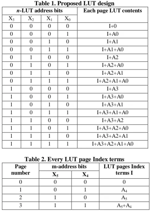
m-n combination enables the look-up table page its corresponding selector module to be selected to achieve the maximum operating frequency. Table.1 and Table 2, respectively, are the structure of the LUT 6th order filter, for
n=4 and m=2 as well indexed terms of each page. Each LUT page includes filter coefficients summation and index term I. The proposed LUT design comprises of the filter coefficients
[image:3.595.306.551.74.419.2]indexed sums, as illustrated in Table.2, rather than consisting in a summation of coefficient in a traditional LUT.
Table 1. Proposed LUT design
n-LUT address bits Each page LUT contents
X3 X2 X1 X0
0 0 0 0 I+0
0 0 0 1 I+A0
0 0 1 0 I+A1
0 0 1 1 I+A1+A0
0 1 0 0 I+A2
0 1 0 1 I+A2+A0
0 1 1 0 I+A2+A1
0 1 1 1 I+A2+A1+A0
1 0 0 0 I+A3
1 0 0 1 I+A3+A0
1 0 1 0 I+A3+A1
1 0 1 1 I+A3+A1+A0
1 1 0 0 I+A3+A2
1 1 0 1 I+A3+A2+A0
1 1 1 0 I+A3+A2+A1
[image:3.595.53.289.327.495.2]1 1 1 1 I+A3+A2+A1+A0
Table 2. Every LUT page Index terms
Page number
m-address bits LUT pages Index terms I
X5 X4
0 0 0 0
1 0 1 A4
2 1 0 A5
3 1 1 A5+A4
A. Realization of proposed architecture
In the following sections, the carried work regarding FIR filter is discussed in detail. It is composed of four main input register components, a look-up table (LUT), a barrel shifter (BS), and a control unit (CU).
A. Input register bank
[image:3.595.306.548.552.660.2]Register Bank of Input, shown in fig.5, with the parallel shift registers N serial-in parallel-out, accepts the input samples for X(n)., n=0,1, .., N-1. Registry contents take a correct shift at every clock pulse and generate B terms of length N.
Fig. 5. Input register bank and address bifurcation
B. Look-up-table unit
The LUT address generated by the bank of the register is divided into two address groups n and m as shown in Figure 6. LSB n bits set the LUT address, while the LUT pages are set to m bits. Four LUT pages are connected in parallel with sixteen locations by 4 address lines. A 4:1 multiplexer unit selects a suitable output for the next stage.
C. Accumulator and Shifter Unit
ensure that complexity of the hardware greatly reduced to the way the LUT is handled and thus an accumulator or shifter is changed to produce partial products.
Fig.6. The proposed structure of the LUT unit D. Control Unit
[image:4.595.320.544.164.652.2]From figure.7, it is clear that the operation flow starts with the RESET=1, the filtering process stays remain in the idle state. When the enable (E=1), begins the filtering process and fetching for LUT for every clock cycle (CLK=1). If the count is equal to 8 it will give the filter output, otherwise, it will add operation accompanied with shift operation for LUT fetching.
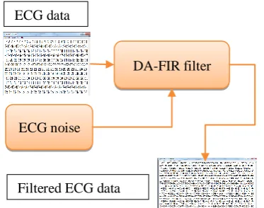
Fig.7. Control unit of a proposed structure E. Application of FIR Filter: ECG System
One of the most critical steps in ECG digital signals is the filtering of noise as ECG signals are affected noisily by many different sources, such as Baseline Wander, EMG interference, and power line noise. Many filters can minimize these noises. In this paper, an HDL FIR-DA filter is to be implemented to reduce high-frequency noise and the interference from power lines. Figure.8 demonstrates the typical shape of an impulse of an ECG signal. Electrically powered electric cardiograph supply is not perfect and can give rise to the proliferation of the electric network noise. This noise is the largest part of the 50 Hz or 60 Hz sinusoid frequency based on the location of the device. The noise is a supplement and adds a useful signal.
Fig.8. Pure ECG signal [15]
[image:4.595.64.256.345.460.2]This gives a signal that cannot be detected from the characteristic ECG signals (P, Q, R, S and T in Figure 8). The design of a narrow-band filter and a notch filter that filters the component at 60 Hz and misses the useful signal is therefore necessary. In addition, it is possible that by recording an ECG signal the mean value of the signal changes due to patient breathing, and this paradox is termed a baseline drift in the literature. The change in the average value is slow, so high-frequency filtering, when the marginal frequency is low, is in the order of 0.5 Hz.
Figure. 9: Flow process of FIR implementation in the Matlab environment
F. Design if FIR filter with Matlab environment:
The strength of MATLAB is that it enables the construction of its own reusable tools. EMG noise from the MIT-BIH noise stress database is accessed in real time in the form of an a.mat file and is imported into a workspace added with pure ECG. The design flow process of FIR implementation in the
Matlab depicted in figure.9.
Apply the ecg_corrupted.mat and display the timing of the signal whose axis should be in seconds. The frequency of selection is fs= 360 Hz.
Design a FIR filter with a high frequency by the optimization method whose intrinsic band fa , impermeable band fp and attenuation in the impermeable (αa) and permeable (αp) band.
Design a FIR filter power line noise filter that should satisfy the following limit relative frequencies:
a) The bandwidth of the bandwidth: Fp1 = (fc - 2 Hz) / fs and Fp2 = (fc + 2 Hz) / fs,
b) The limit frequencies of the impervious bands: Fa1 = (fc - 0.5 Hz) / fs and Fa2 = (fc + 0.5 Hz) / fs.
If the dimensions are not met, the functions need to change the order of the filter until they become satisfied
Using the baseline_drift_filter function, design a filter where fa= 0.4 Hz, fp = 1 Hz, αa = 30 dB and
αp = 0,5 dB. Filter the loaded ECG signal. Draw the timeline of the output signal.
[image:4.595.48.269.636.765.2]G. Design if FIR filter with Xilinx environment
The following are the specification of the filter as follows:
Order of the filter: 10
Number of Taps: 11
Integer coefficients: 8-bit signed
Table 3. Coefficient terms for ECG denoising Coefficients of
filter
8-bit integer Hexadecimal equivalent
h0 -15 F1
h1 -13 F3
h2 7 07
h3 38 26
h4 66 42
h5 78 4E
h6 66 42
h7 38 26
h8 7 07
h9 -13 F3
h10 -15 F1
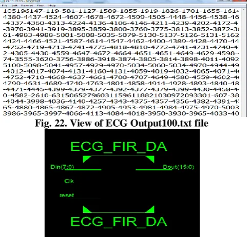
[image:5.595.303.545.49.259.2]The VHDL code for the FIR filter is simulated and verified in comparison with I-Sim’s simulated results with Matlab's correct results. Input.txt files contain samples of ECG input, the VHDL filter code reads these ECG files, applies digital filtering, and writes output.txt files are shown in Figure.10, for verification. After simulations in Xilinx Isim, the filtered output is written for verification in output.txt. The test is done by making comparisons the output file with the correct Matlab results.
Figure.10: FPGA based DA-FIR filter of the proposed approach
IV. RESULTS & DISCUSSION
The filter was first designed in MATLAB to examine the viability of the requirements in MATLAB. In MATLAB we have the desired results. The filter was then designed in HDL with the desired specifications and simulated in Modelsim Altera 10.1b. Xilinx ISE 14.4 designs the FIR filter which uses both enhanced DA and fast FIR, and is implemented in Virtex-6 FPGA. Results of simulation show that DA-designated FIR filters can save significant hardware resources by using LUT to replace MAC units and a smaller scope compared to traditional filter implementation.
Figure.11: DA_FIR filter top-level entity
Table 4: Comparison of the various parameters Parameters LUT based
FIR-DA
Proposed FIR-DA
Delay(ns) 7.56 5.49
Area-delay product (ADP)
210625 196480
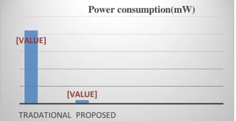
Power consumption
[image:5.595.307.548.288.497.2]0.211mW 0.011mW
Table 5: FPGA resources (Area resources)
Logic functions LUT based FIR-DA
Proposed FIR-DA
Adders 2 2
Counters 3 1
Registers 205 205
Multiplexers 26 18
[image:5.595.68.255.421.568.2]Logic shifters 4 2
Fig. 12. Comparison of performance metrics of DA_FIR filter for delay
Fig. 13. Comparison of performance metrics of DA_FIR filter for Area
[VALUE]
[VALUE]
TRADATIONAL PROPOSED
Delay(ns)
[VALUE]
[VALUE]
TRADATIONAL PROPOSED
Area-delay product (ADP) DA-FIR filter
ECG data
Filtered ECG data data
[image:5.595.305.547.472.658.2]Fig. 14. Comparison of performance metrics of DA_FIR filter for power
[image:6.595.49.289.52.175.2]Two different filters, such as the traditional DA - FIR filter (MUX - LUT DA) and the proposed LUT indexed DA - FIR filter is shown in (Fig.12 – 14) from the above delay, area and power report. The proposed Area Delay Product (ADP) is less than traditional.
Fig. 15. Comparison of filtering effects of fixed and double precision of filtered output
[image:6.595.48.292.263.425.2]Figure15 illustrates that the filtered output of both fixed and double precision differs more in filtering at initial intervals only (i.e. from 0 to 3200).
Fig. 16. Original ECG corrupted signal
Fig. 17. ECG signal leaked through VF filter
Fig. 18. ECG signal leaked through VF filter NPO
Fig. 19. Phase characteristics of VF filter
Fig. 20. Phase characteristics of NPO filter It is clear from fig.19 and fig.20 that for 0.5Hz the VF filter phase is -200 when the filter is -100 in the case of the NPO, similarly for 3Hz -1300 VF and -700 in the case of NPO filter, with a 50% decrease in NPO for the VF filter. Therefore, the order necessary for the VF filter is 833 and the order necessary for the NPO filter is 473 which indicates only NPO filter outperformance.
Fig. 21. View of ECG Input100.txt file [VALUE]
[VALUE]
TRADATIONAL PROPOSED
[image:6.595.46.289.462.742.2]Fig. 22. View of ECG Output100.txt file
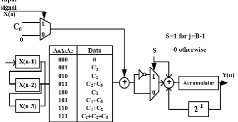
Fig. 23. The top module of ECG FIR filter using DA
V. CONCLUSION
In this paper, a simplistic formulation on FIR filters using DA has been provided and two cost-effective structures have been proposed. In addition, DA based LUTs were divided into small orders of parallel DA based LUTs for higher order filters which decreased the delay in the critical path, and the use of a single step parallel unit separates the critical path from the filter order. The proposed compact FIR filter is introduced using quick FIR algorithmic DA, with the result that high performance and low power consumption are achieved through the accumulator phase. LUT indexing limits rapid growth and removes the need for additional devices, which leads to a decrease in the critical pathway and optimizes operating frequency. The filter reliability is analyzed by the ECG noise reduction method. Synthesis results demonstrate that there are significant improvements in the performance, power consumption, and area required for both the proposed structures than for the classical filter order.
REFERENCES
1. M. S. Chavan, R. Agarwala, and M. Upland, “Design and implementation of digital FIR equiripple notch filter on ECG signal for removal of power line interference,” WSEAS transactions on signal processing, vol. 4, no. 4, pp. 221–230, 2008.
2. S.A. White, “Applications of Distributed arithmetic to digital signal processing: A tutorial review,” IEEE ASSP Magazine, vol.6, no. 3, pp.a5-19 Jul. 1989.
3. D.J. Allred, H.Yoo, V.krishnan, W.Huang and D.V. Anderson, “LMS adaptive filters using distributed arithmetic for high throughput,” IEEE Transactions on Circuits and Systems I: Regular Papers, vol. 52, no. 7, pp. 1327-1337, July 2005. 4. A.Peled and B.Liu, “A new hardware realization of digital
filters,” IEEE Transaction Acoust. Speech, Signal Process. vol. 22, pp. 456-462, Dec. 1974.
5. S.Y. Park and P.K. Meher, “Low-Power, High –Throughput, and Low Area Adaptive FIR Filter Based on Distributed Arithmetic”, IEEE Transactions on Circuits and Systems-II, pp. 346-350, 2013.
6. P.K. Meher and S.Y. Park, “High-throughput pipelined realization of adaptive FIR filter based on distributed arithmetic,” in IEEE International Conference on Very Large Scale Integration, pp. 428-433, Oct.2011.
7. G.A. Clark, S.K. Mitra and S.R. Parker, “Block implementation of adaptive digital filters,” IEEE Trans. Circuits Systems, vol.28, pp. 584-592, Jun. 1981.
8. S.Baghel and R. Shaik, “FPGA implementation of fast block LMS adaptive filter using distributed arithmetic for high throughput,” Proc. Int. Conf. Commun. Signal Process (ICCSP), pp. 443-447, Feb. 10-12, 2011.
9. B.K. Mohanty and P.K. Meher, “A high- performance energy efficient architecture for FIR adaptive filter based onthe new distributed arithmetic formulation of block LMS algorithm,” IEEE Trans. Signal Processing, vol .61, no. 4, pp. 921-932, Feb 2013.
10. B.K. Mohanty, P.K. Meher and S.K. Patel, “LUT Optimization for Distributed Arithmetic -Based Block Least Mean Square Adaptive Filter,” IEEE Transactions on Very Large Scale Integration(VLSI) Systems, vol. 24, no. 5, pp.1926-1935, April 2016.
11. H. Yoo, and D. Anderson, “Hardware-Efficient Distributed Arithmetic Architecture for High-Order Digital Filters”, in Proc. IEEE International Conference on Acoustics, Speech, and Signal Processing (ICASSP '05), 2005, Vol. 5, pp. 125 – 128. 12. Özalevli E, Huang W, Hasler PE, Anderson DV.A
Reconfigurable Mixed-Signal VLSI Implementation of Distributed Arithmetic Used for Finite-Impulse Response Filtering. IEEE Transactions on Circuits and Systems I, Regular Papers. 2008 Mar; 55(2):510–21.
13. Meher PK. New Approach to Look-Up-Table Design and Memory-Based Realization of FIR Digital Filter. IEEE Transactions on Circuits and Systems I, Regular Papers. 2010 Mar; 57(3):592–603.
14. Peled A, Liu B. A new hardware realization of digital filters. IEEE Transactions on Acoustics Speech and Signal Processing. 1974 Dec; ASSP-22(6):456–62.
[image:7.595.322.554.351.719.2]15. B. Pradeep Kumar and S. Balambigai, February 2012, ‘ A Survey on ECG De-Noising Techniques, Bonfring International Journal of advances in Image Processing’, Vol. 2, Special Issue 1, Part 1.
Figure. 24. Simulation of Input100.txt ECG data
Figure. 25. Simulation of Input101.txt ECG data
AUTHORS PROFILE
Pratyusha Chowdari. Ch, Received the B.E degree in Electronics and Communication Engineering from Andhra University, India, in 2009. And M.Tech degree in VLSI Design from Andhra University, India in 2011. She is currently working as an Assistant Professor in GRIET, Hyderabad. Her research interests include VLSI and Signal Processing.
![Fig.8. Pure ECG signal [15]](https://thumb-us.123doks.com/thumbv2/123dok_us/8189372.257352/4.595.52.292.86.221/fig-pure-ecg-signal.webp)