Abstract- The moto of this paper is to develop an unmanned aerial vehicle equipped with modern technologies used for auto pilot video recording Application. In this paper we proposed a method todesigna quadcopter to record the video in any location using Linux operating system. we use Raspberry Pi micro controller for flight control operation. we have developed a cloud based solution by creating a Wi-Fi network connection between the laptop and theflightcontrollerboard with the help of raspberry pi micro controller to produce “Hard Real Time output” .The quadcopter will able to acquire Additional characteristics such as • Altitude and longitude • Auto pilot • Speed • Detects ground level and height • Geographic coordinates. The Raspberry PI Micro controller is interfaced with two cameras having 1080-pixel resolution and captures 30 frames per second. The camera size is very small and light weight with good quality interfaced with quadcopter to record the videos. The proposed system can reduce the manpower involved in live outdoor video recording camera man system
Keywords—Accelerometer, Raspberry pi µ-controller, Brushless DC-Motor, KK2.1.5 Flight controller Board, Electronic speed controller, Radio Calibration, Transmitter and receiver, Wi-Fi Module.
I. INTRODUCTION
Quadcopterisanassistivedevicewhichhasahighdemandin the industrial & surveillance sector.Remote location control quadcopters can be controlled by using microprocessors or dedicated flight controllers. In this proposed Auto pilot video recording quadcopter can be
controlled by using Raspberry-pi
microcontrollerrunningon Linuxoperatingsystem. It controllers all the flight control operations without using anyadditional support of micro controller like Arduino-UNO .Many people have thought that Raspberry Pi doesn‟t work in real time mode, because it may have trouble in reading/receiving the sensor data and transmits commands to the motor at appropriate timing, otherwise it will leads to instability. In this method our Raspberry Pi
Revised Manuscript Received on October 05, 2019.
Dr. Shaik Masood Ahamed: LMISTE, LMCSI, MIE, MNSPE(USA), MAISES(USA), Professor-Dept. of CSE, Aurora Scientific Technological Reasearch Academy, Bandlaguda, Hyderabad
Prof. Dr.V. Lobo: Professor-Dept. of Chemistry,Aurora Scientific Technological Reasearch Academy, Bandlaguda, Hyderabad
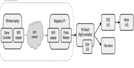
[image:1.595.309.540.376.493.2]microcontroller will resolves all the problems without using any additional micro controller. Initially we have developed a cloud based system by creating a secure Wi-Fi network connection between the laptop and theflight controller through with the help of raspberry pi micro controller to produce “Hard Real Time output” running on a Linux operating system. The auto pilot video recording flight control operating code are written by using C- python Language using the code the quad copter will able to acquire thecharacteristicssuch as • Altitude and longitude • Auto pilot • Speed • Detects ground level and height • Geographic coordinates.
Figure 1 Block Diagram of cloud Based system. II. HARDWAREDESIGNSPECIFICATIONOF
QUADCOPTER
The proposed design of Auto pilot quadcopter based video recording system has to follow ten different steps in a sequential manner
1. Arranging the Frame 2. Soldering the PCB board
3. Interfacing the Electronic Speed Controller 4. Placing of Brushless DC - motors
5. Propellers Arrangement
6. Interfacing the Flight controller KK2.1.5 7. Radio Calibration Transmitter.
8. Interfacing Auto pilot channel with Receiver. 9. Adjusting
the receiver parameters to IDLE.
10.Testing the Quad copterFrame principle2.1ARRANGINGTHEFRAME
Frame is the physical structureof quad-copter.it is used to attach all the components
together.
Design and Development of Linux
Based Quadcopter Cameraman System
using Raspberry Pi Microcontroller
And it can be arranged in three different fashions they are „+‟, „X‟,‟ H‟. The selection of frame arrangement fashion is depends uponuser choice. To construct the frame we can use three different materials they are metal, plastic, and wood. To construct a wooden frame, take a wooden sheet and add a rectangular piece in the central part of this frame. Frame size here we used as 15 cm height and 6cm breath, and 2mm thickness. To inter-connect these frames use nails and glue. In case if we decide to construct the metal frame or plastic, the dimensions are same but connections are different.
Fig 2 Frame
In the proposed method Auto Pilot video recording system .wehave chosen HJ- 450 Frame. It supports all multi-rotor designed principle and auto- pilots operations. Arrange the frame HJ540 in a „X‟ arrangement Fashion.
Security protection methods:
Before flying the quad copter various security protection methods to be followedthey are.
During flying mode Place the quad copter away from
objects and obstacles
Don‟t go closer to the propeller when it is in flying
mode.
During flying mode Don‟t touch the BLDC motors
and propellers.
Don‟t overload multi-rotorbrushless DC -motor. Check that the Brushless DC-motor and
Propellerconfigurations are arranged properly
beforeflying the drone.
During flying mode,Check the rotation of each
propeller rotating in Appropriate direction or not.
2.2 Soldering the PCB
[image:2.595.87.240.190.320.2]Chassis which is inbuilt with HJ-450 frame. it has to be soldered for connecting the Electronic Speed Controller. The frame Chassis operates as a printed circuit board to ensure the power supply for the frame. We have used Insulating material for soldering. During soldiering there should not be any open or close circuit.
Fig 3 Chasis
2.3 Interfacing the Electronic Speed Controller
After the arrangement of HJ450 framewith the Chassis. The next step is to Interface Electronics speed controller at four junctions to HJ450 frame chassis using cables and after connecting the four nodes with electronic Speed controller (ESC).Proper Soldering have tobe done at four junctions. Otherwise it tends to get short circuit.
[image:2.595.337.519.239.338.2]
Fig 4 interfacingthe Electronic Speed Controller
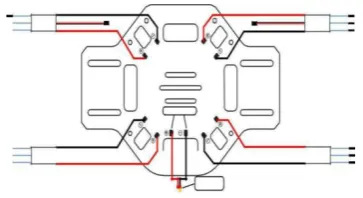
Fig 5 overview of HJ450 frame 2.4 Placing of Brushless DC Motors
After connecting the Electronic Speed Controller with the Frame chassis .Next step we have to place four brushlessDC motors of 1000 KV each. Interfacing the Brushless DC motor to Electronic Speed Controller is to be done very carefully without getting any burst in winding. The three bullets are connected to brushless DC motor is to be connected with Electronic Speed Controller.
[image:2.595.324.546.375.498.2] [image:2.595.310.518.611.711.2]2.5 Propeller Arrangement
Multi-rotor brushless DC motor enables a highspeed and stable flight control operation, Each rotor of brushless DC motor works with other‟s Brushless DC motor thrust points. Each brushless DC motor rotor is connected with 9 -inch metal Propeller. It is available for low price in the market. These are highly durable and it won‟t bend easily if the quad copter hits any obstacle during flying.
[image:3.595.347.504.215.325.2]After attaching brushless DC motors we need to fourmetal propellers. Place two propellers in clockwise direction and two Propellers in Anti clock wise direction.
Fig 7 propellers 2.6Interfacing TheFlight controller KK2.1.5
After connecting the propellers the next step is to set
the values in the Flight controller KK2.1.5. in the
“LOAD MOTOR LAYOUT”. The Next step is to
Check the directions of motors which rotates in clock
wise and counter clock wise direction. Second we need
to set PI controller settings as:
Roll/Pitch Axis:
Pgain = 50
Plimit = 100
Igain = 25
Ilimit = 20
Yaw Axis:
Pgain = 50
Plimit = 20
Igain = 25
Ilimit = 10
Default gains are set to 50/50/50 (roll/pitch/yaw) P-term, and 25, 25, 50 I-term.
2.7 RADIO CALIBRATION
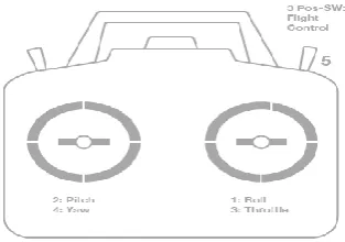
Radio Calibration transmitter is used for controlling the quad copter motion control management. it has six channels and two modes they are Channel 1: Roll, Channel 2: Pitch, Channel 3: Throttle, Channel 4: Yaw, Channel 5: Flight modes (AUTO TO ANUAL), Channel 6: Operates geared gripper mechanism.
All the combined control signals are integrated tothe Radio calibration transmitter and Receiver through autopilot channels from the Respective receiver.
Calibrating every input signal from sticks/switches of Radio calibration transmitter controls/channels can be done by
simply rotating the switches/sticks from minimum position to Maximum value. And Record the maximum and minimum positions value.
2.7.1Transmitter configuration
There are two main transmitter configurations:
Mode 1: left stick/ switches movement will controls the channel 2 : pitch and channel 4 :yaw operation , and the proper stick/switch can controls the operation of Channel 3 :throttle and channel 1 :roll operation.
Mode 2: left switch can control the channel 3: throttle and channel 4: yaw operation. the proper stick can control the operation of channel 2: pitch and channel 1: roll operation.
FIG 8.Transmitter(Mode 1): Recommended Channels
2.8 Interfacing Auto pilot channel with Receiver
Using the USB port interface the autopilot channel with Receiver and turn on the Radio Calibration transmitter. Test the Radio calibration transmitter is connected to the receiver (by checking the receiver displays a solid inexperienced light).
III. OVERVIEWOFDIFFERENT
COMMUNICATIONPROTOCOL
The local control STM32F3 firststepit communicate with Raspberry PI module via USB-cable. Through a un -manned area vehicles Talk2 protocol and it also communicate with high level objects. BecausetheUAVTalk protocol act as a bi – directional communication interface.in one end it is interfaced local control and other end is interfaced with global control, all useful parts of data are available as a UAVObject.
Figure9: Overview of different communication protocols.
[image:3.595.312.553.563.680.2]The UAVObjects data information on the local control which can be easily accessible on a laptop, using a WiFi or an Ethernet connection.
3.1 Laptop
The flight controller is connected through the laptop through the Wi-Fi adaptor module and it runs on Linux operating system, so it gives provisional to create a cloud based data environment to share the data from one remote location to another location through internet connection.
3.2 Barometer
The barometer peripheral is interfaced with Raspberry PI module by using I²C current driver module. The Raspberry PI module transfers the latitude, longitude and attitude data from barometer to the STM32F3-Discovery using the UAV-Objectsand the UAV-Talk protocol.
3.3 Camera
The cameras are interfaced to the Raspberry PI module with flat-cable through CSI3-interface.
We have chosen the Raspberry PI having two cameras having 1080-pixel resolution and capture 30 frames per second. The camera size is very small and light weight with good quality interfaced with quad copter to record the videos
To enhance more features in the quad copter, the Raspberry PI microcontroller has acamera peripheral interface ( CSI) interface. CSI supports the camera to record 1080 pixel quality resolution through a Five megapixel sensor and it records 30 frames per second. The Raspberry PI provides an open-source driver for the camera used for processing the images which provides good quality resolution output. The camera software provides two commands to operate the camera; raspivid and raspistill. raspivid is a command line application that allows torecord the video, while the second command raspistill allows you to capture images. By using this we can record and capture the image and videos. using this feature we have implemented an auto pilot Video recording system.
Fig 10 Camera interfaced with raspberry Pi Module
IV. SOFTWAREIMPLEMENTATIONAND
EXECUTION
To make the quadcopter for flying and recording the videos , we need control software to control from ground to top. (i.e local control and global control )
4.1 Local control
Here we use the open source software project module named as TauLabs4For local control operation. We choose this open
source software project module, because it easy to interface the hardware STM32F3Discovery.
4.2 Global control
The software for “Ground Control Station” (GCS) programmed in Python language to control local and ground station. This program runs on your computer and communicated with the local control to provide configuration options and means of debugging and monitoring.
We have written own programming for global control station by using python language. This program runs on a Raspberry PI module which allows, it to communicate with the local control using UAVObject,
4.2.1 Recorder plugin
This plugin monitors the “Armed” flag in the “Flight Status” UAVObject, and as soon as the quad copter gets armed, it starts recording video on both Raspberry PIs. On disarming, the recording stops. This allows us to easily create in-flight footage with the cameras.
V. SOFTWAREEXECUTIONINLINUX OPERATINGSYSTEM
STEP-1: OPEN THE PUTTY OFTWARE
STEP-2:TYPE IP ADDRESS TO CONNECT WITH RASPBERRYPI
STEP-3:LOGIN AS “PI” & ENTER THE PASSWORD AS “RASPBERRY”
STEP-4:WHEN CONNECTED TYPE COMMAND “python_test connection.py” AND ENTER.
STEP-5:PROGRAM STARTS EXECUTING
STEP-6:DRONE STARTS AUTONOMOUSLY
STEP-7:DRONE REACHES LOCATION AND STARTS RECOEDING THE VIDEO
VI. CONCLUSION
Our Proposed model hasachieved a successful development of Linux and raspberry pi-basedQuad copter for Autopilot cameraman system in affordable price. Quad copter can be easily designed and assembled by using these shelf components.Itcanbeusedasalowcostalternativetovarious applications which includes pesticide sprinkling in Agricultural Lands, end to end delivery within the
transmitter‟s RF range, surveillance in
defenseandothersensitiveplaceslikenationborder,mapping through remote sensing, etc. with very high level ofprecision. In future we
such as pollution control, weather forecasting and live recording through the quadcopter. The proposed system has successfully reduced the manpower involved in outdoor video recording camera man system.
REFERENCES
1. Akki, V. V. R., & Kumar, G. Dgs Based Frequency Reconfigurable Microstrip Patch Antenna For Cognitive Radio And Wi-Max Applications.
2. Stafford, Jesse, "How a Quadcopter works Clay Allen". University of Alaska, Fairbanks. Retrieved2015-01-20.
3. SandeeepKhajure, VaibhavSurwade, VivekBadak, “Quadcopter Design and Fabrication,” International Advance Research Journal in Science, Engineering and Technology (IARJSET), Vol. 3, Issue2, February2016. 4. Bhatnagar, R. U. C. H. I. R., & Birla, K. V. (2015). Wi-Fi Security: A Literature Review of Security in Wireless Network. IMPACT: IJRET, 3(5), 23-30.
5. 5.QuadcopterDynamics,Simulation,andControl,January 26, 2010. 6. David Roberts, "Construction and Testing of a
Quadcopter," California Polytechnic State University, San Luis Obispo, CA, 93407, June,2013.
7. Venugopal, N., & Dongre, M. A Novel Technique That Maximizes Ergodic And Outage Capacity For Enhanced Spectrum Sharing In Cognitive Radio Network.
8. 8 S. Bouabdallah, P. Murrieri, R. Siegwart, "Design and Control of an Indoor Micro Quadrotor", Robotics and Automation 2004. Proceedings. ICRA „04. 2004 IEEE International Conference on, vol. 5, pp. 4393-4398, 2004.
9. Sharma, A., & Thakur, D. (2017). A review on wlans with radio-over-fiber technology. International Journal of Electronics and Communication Engineering (IJECE), 6(5), 1-6.
10. J. Engel, J. Sturm, D. Cremers, "Camera-based navigation of a low-cost quadrocopter", IEEE/RSJ, International Conference on
Intelligent Robots and
Systems(IROS),pp.2815-2821,Oct.2012,ISBN2153-0858.
11. 11 J. Valvano, "Embedded Microcomputer Systems: Real Time Interfacing", Brooks-Cole, 2000, ISBN0534366422.
12. Chourasia, R. C., & Bhardwaj, A. K. (2014). Design Estimation Of Brushless SEDC Motor For Speed Control By Using Various Controllers. IJEEER ISSN (P).
AUTHORS PROFILE
Dr. Shaik Masood Ahamed, B.E, M.Tech, Ph.D,
LMISTE, LMCSI, MIE, MNSPE(USA),
MAISES(USA) Professor-Dept. of CSE, Aurora‟s Scientific and Technological Research Academy, Hyderabad Dr. Shaik Masood Ahamed received his Bachelors degree in Engineering from Osmania University, Hyderabad in 1991 and Masters in CSE in 1999.He did his Ph.d in CSE . He started his professional career as a academician who turns into a Software Consultant in various Positions in USA with EDS,IBM in Illinois, USA and Accenture in India and USA for over 10 years. Later after returning from Accenture he headed in reputed Engineering colleges in India. He has published 18 research papers to his credit in many National,International Journals and many Conference Proceedings. He has 23 years of experience in both teaching and Research fields. His areas of interests are Artificial Intelligence, Wireless Sensor Networks and Image Processing. He is reviewer for many reputed National and International Journals.
Prof. V. Lobo did his graduation (B.Sc.),
post-graduation (M.Sc.) and doctoral (Ph.D.)
research from the University of
Bombay, Bombay. He did his doctoral research with a Minor Research Project awarded by the University Grants Commission (UGC), New Delhi. The topic of his research was "Separation of some elements using ion-exchangers and neutron activation analysis". He has also completed a research project sponsored by the University of Bombay. He has presented several research papers in various conferences in India and abroad. He has published six research papers in journals of national and international repute. He has visited several countries such as Austria, Qatar, Slovakia, Turkey,
USA and Yemen for Symposia / Seminar /Educational activities. He is a member of the Royal Society of Chemistry, UK, and Chemical Society of Ethiopia.
Currently he is serving as Professor of Chemistry in ASTRA,
Moosarambagh, Hyderabad. He teaches engineering chemistry,
environmental science and soft skills to B.Tech students as Professor of Chemistry. He has also taught Instrumental Methods I, Instrumental Methods II in Modular Programme of European Credit Transfer System. He has also been assigned teach post-graduate students in chemistry. I have
completed National Programme on Technology EnhancedLearning courses