Miniaturized Microstrip Branch-Line Coupler with Good Harmonic
Suppression Based on Radial Stub Loaded Resonators
Hai Zhang1 and Zhijie Zhang2, *
Abstract—In this paper, a novel miniaturized microstrip branch-line coupler (BLC) with good harmonic suppression using radial stub loaded resonators is proposed. The novel structure has two significant advantages, which not only effectively reduces the occupied area to 10.3% of the conventional BLC at 0.5 GHz, but also has high 14th harmonic suppression performance. The measured results indicate that a bandwidth of more than 121 MHz has been achieved while the phase difference between
S21 and S31 is within 90◦ ±1.5◦. The measured bandwidth of |S21| and |S31| within 3 ±0.4 dB are
146 MHz and 151 MHz, respectively. Furthermore, the measured insertion loss is comparable to that of a conventional BLC. To validate the design concept, a new miniaturized planar BLC with good harmonic suppression using radial stub loaded resonators is designed and fabricated. Simulated and experimental results are achieved with good agreement.
1. INTRODUCTION
Branch-line coupler (BLC) is widely used at microwave frequencies in the design of microwave circuits such as power dividers, balanced amplifiers, and balanced filters [1]. Currently there are two drawbacks for the conventional microstrip BLC design. Firstly, a conventional BLC is composed of four quarter-wavelength transmission-line sections at the designed frequency, which will result in a large occupied area especially at low frequency. Secondly, the conventional design also has harmonics that occur at integral multiples of the fundamental operation frequency. These properties will degrade the performance of the coupler. Therefore, much work has been reported in recent years to achieve both compact design and harmonic suppression for the BLC [2–15].
Usually there are two methods to design a compact planar microstrip BLC with harmonic suppression. The first method is to load the coupler with shunt open-stubs. By loading shunt open-stubs inside the free area of the BLC, a BLC was designed with a size reduction of 37% to the conventional design at 1.8 GHz [5]. Based on a similar idea, a BLC was proposed that had the properties of 42% size reduction at 2.4 GHz and 5th harmonics suppression [6]. However, further improvement should be carried out on size reduction and harmonic suppression. The second design method is to introduce slow-wave resonators in the coupler structure. Using compensated spiral compact microstrip resonant cells, a BLC was introduced with its area reduced to 24% of the conventional one together with 2nd and 3rd harmonics suppression at 2.4 GHz. However, the isolation performance is not ideal [7]. By introducing high-low impedance resonators inside the free area of the coupler, a slow-wave BLC was proposed with its area reduced to 28% of the conventional one at 2.0 GHz. Even so, it only has 2nd harmonic suppression performance [8]. On the other hand, size reduction methods were also reported in [9–11]. These couplers achieved compact size, but the harmonic suppressions needed improvement.
Received 1 July 2019, Accepted 9 August 2019, Scheduled 29 August 2019
* Corresponding author: Zhijie Zhang ([email protected]).
1 College of Information Science and Engineering, Huaqiao University, Xiamen 361021, China. 2 Department of Electrical and
A new microstrip BLC with compact size and wideband harmonic suppression using radial stub loaded resonators is present based on our previous works [12]. For this purpose, one BLC with operation central frequency located at 0.5 GHz using radial stub loaded resonators is designed, fabricated, and measured. Measured results indicate that the proposed branch coupler not only effectively reduces the occupied area to 10.3% of the conventional BLC at the same operation frequency, but also has high 14th harmonic suppression performance. Furthermore, the proposed novel coupler has a bandwidth of more than 121 MHz, while the phase difference between S21 and S31 is within 90◦ ±1.5◦. To validate
the design theory, a new miniaturized planar BLC with good harmonic suppression using radial stub loaded resonators has been designed and fabricated. Good agreement between measured and simulated results is provided.
2. CIRCUIT DESIGN
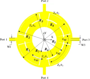
The layout of the proposed BLC is shown in Fig. 1, which consists of eight radial stub resonators loaded inside the free area of a conventional BLC. Each radial stub resonator is composed of a short high-impedance line and a long low-impedance line. The length of the high-impedance line is very short and less thanλ/10, whereλis the guided wavelength at the operation frequency. Therefore, each high-impedance line can be deemed as a lumped element with negligibly small value. The inductance effect to the per unit length of the main transmission lines between two adjacent ports can be ignored since it is trivial. The capacitances caused by the low-impedance lines are loaded parallel with the main transmission lines in a distributed form. This will increase the per unit length capacitance of the main transmission lines between two adjacent ports.
Port 2
Port 4 W1
Port 1
W3 Port 3
Z2,θ2
Z3,θ3
Z1,θ1
Z4,θ4
Y X
θ02
θ01
R1 R2
R3
R4
R5
θ03
R6 R7
Figure 1. Topology of the proposed BLC.
Figure 2 shows the equivalent circuit of the proposed BLC [15]. We can clearly see from this figure that the loaded high-low impedance resonators will introduce extra parallel capacitances denoted asC11
and C12 in the coupler, where C11 and C12 are the capacitances caused by the couplings between the
loaded resonators and the ground. The propagation constant β and working frequency are given by:
fc = 2π√1L
0C0
(2)
whereL0 andC0 are the distributed inductance and capacitance for the main line of the BLC per unit
length, respectively, andC1 is the effective distributed capacitance per unit length caused by the shunt
capacitance C11 and C12. The proposed BLC is designed based on the slow-wave loading mentioned
above.
Port 1
Port 2
Port 3
Port 4
Z3,θ3 Z2,θ2 Z2,θ2
Z2,θ2 Z2,θ2
Z3,θ3
Z3,θ3 Z3,θ3 C11
C12 C12
C11
C12 C11 C12
C11
Figure 2. Equivalent circuit of the proposed BLC.
With further optimal design by the full-wave electronic magnetic (EM) simulation software, the final structure parameters of the proposed BLC are as follows: W1 = 1.7 mm, W2 = 1.0 mm,R1= 17.7 mm,
R2 = 17.3 mm, R3 = 17.0 mm, R4 = 16.2 mm,R5 = 13.0 mm, R6 = 12.0 mm, R7 = 8.0 mm,θ01 = 20◦,
θ02 = 63◦,θ03 = 34◦. They can be easily implemented by the standard printed-circuit-board etching
processes. The substrate used here has a relative dielectric constant of 2.94 and thickness of 0.762 mm, and the total area of the proposed BLC is 630.12 mm2.
3. SIMULATION AND MEASUREMENT RESULTS
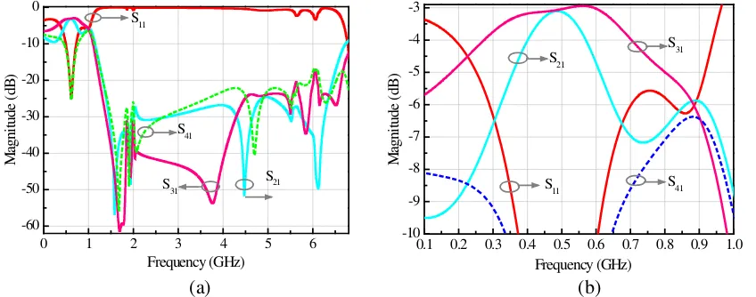
Simulation was completed with HFSS 14.0. Measurement was carried out on an Agilent 8511B network analyzer. Fig. 3 shows the simulated results ofS-parameters. Fig. 4 shows the measured S-parameters
0 1 2 3 4 5 6
-60 -50 -40 -30 -20 -10 0
S31 S21
M
agni
tude
(
dB
)
Frequency (GHz) S11
S41
0.1 0.2 0.3 0.4 0.5 0.6 0.7 0.8 0.9 1.0 -10
-9 -8 -7 -6 -5 -4 -3
S31 S21
S11 S41
M
agni
tude
(
dB
)
Frequency (GHz)
(a) (b)
of the proposed BLC. We can find that they are in good agreement. Referring to the measured results in Fig. 4, the central frequency located at 0.5 GHz can be clearly observed. At this central frequency, the measuredS21is 3.12 dB, andS31is 3.10 dB, while the measured bandwidth of|S21|and |S31|within
3±0.5 dB are 146 MHz and 151 MHz, respectively.
0 1 2 3 4 5 6 7
-60 -50 -40 -30 -20 -10 0 S41 S11 S31 M agni tude ( dB ) Frequency (GHz) S21
0.1 0.2 0.3 0.4 0.5 0.6 0.7 0.8 0.9 1.0 -10 -9 -8 -7 -6 -5 -4 -3 S31 S21
S11 S41
M agni tude ( dB ) Frequency (GHz) (a) (b)
Figure 4. Measured S-parameters of the proposed BLC. (a) Frequency range of 0.1 to 7.0 GHz. (b) Frequency range of 0.1 to 1.0 GHz.
0.1 0.2 0.3 0.4 0.5 0.6 0.7 0.8 0.9 1.0 0 30 60 90 120 150 180 Measurement Simulation P hase D if fe re nce ( D eg ) Frequency (GHz)
Figure 5. Phase difference between S21 andS31.
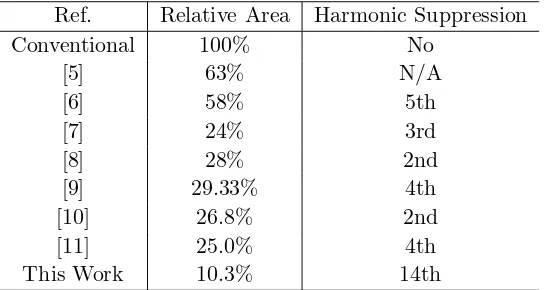
Table 1. Performance comparison of other couplers.
Ref. Relative Area Harmonic Suppression Conventional 100% No
[5] 63% N/A
[6] 58% 5th
[7] 24% 3rd
[8] 28% 2nd
[9] 29.33% 4th
[10] 26.8% 2nd
[11] 25.0% 4th
We can also observe that the 14th harmonic signals have been effectively suppressed withS21 and
S31 lower than a criterion of −10 dB from Fig. 4(a). This means that the proposed new coupler can
protect specialized communication system from the interference of the unwanted signals from 1.0 GHz to 7.0 GHz. This property is very useful for modern communication system to operation in high performance. In order to study the size reduction performance, we investigated the circuit area of conventional one at the same frequency and found that the cost area is 3089.77 mm2. This means that the proposed BLC can effectively reduce the occupied area to 10.3% of the conventional coupler.
Figure 5 shows the phase difference betweenS21 andS31. According to a criterion of ±1.5◦ around
the optimum 90◦ phase difference, the frequency range is from 0.44 GHz to 0.56 GHz corresponding to a bandwidth 24.0%. To demonstrate the superior performance of the proposed coupler, Table 1 shows the performance comparison of the proposed design with several previous designs. The advantages of the proposed coupler can be clearly observed.
4. CONCLUSION
In this work, a new miniaturized planar BLC with good harmonic suppression using radial stub loaded resonators is proposed. Due to eight radial stub resonators placed inside the free area of a conventional BLC, the novel structure has effectively reduced the occupied area to 10.3% of the conventional design at 0.5 GHz and has high 14th harmonic suppression performance. One sample microstrip BLC has been fabricated, measured, and compared with the previous designs. Results indicate that the proposed coupler has the properties of compact size, low insertion loss, and wideband harmonic suppression performance. To summarize, the proposed planar BLC is very useful for modern wireless communication systems owing to its marked properties of simple topology, compact size, and excellent performance.
ACKNOWLEDGMENT
This work was supported by the Natural Science Foundation of Fujian Province, China (Grant No. 2017J01115), and the Undergraduate Education and Teaching Reform Project of Fujian Province, China (Grant No. FBJG20170151).
REFERENCES
1. Pozar, D. M., Microwave Engineering, 3rd Edition, Chap. 7, 333–337, Wiley, New York, 2005. 2. Mohra, A., A. F. Sheta, and S. F. Mahmoud, “New compact 3 dB 0/180 microstrip coupler
configurations,”Applied Computational Electromagnetics Society (ACES) Journal, Vol. 19, No. 2, 108–112, Jul. 2004.
3. Xiao, B., J. Hong, and B. Wang, “A novel UWB out-of-phase four-way power divider,” Applied Computational Electromagnetics Society (ACES) Journal, Vol. 26, No. 10, 863–867, Oct. 2011. 4. Shamaileh, K. A., A. Qaroot, N. Dib, and A. Sheta, “Design of miniaturized unequal split
Wilkinson power divider with harmonics suppression using non-uniform transmission lines,”Applied Computational Electromagnetics Society Journal, Vol. 26, No. 6, 530–538, Jun. 2011.
5. Eccleston, K. W. and S. H. M. Ong, “Compact planar microstripline branch-line and rat-race couplers,”IEEE Trans. Microw. Theory Tech., Vol. 51, No. 10, 2119–2125, Oct. 2003.
6. Mondal, P. and A. Chakrabarty, “Design of miniaturized branch-line and rat-race hybrid couplers with harmonics suppression,”IET Microw. Antennas Propag., Vol. 3, No. 1, 109–116, Jan. 2009. 7. Gu, J. and X. Sun, “Miniaturization and harmonic suppression of branch-line and rat-race hybrid
coupler using compensating spiral compact microstrip resonant cell,”IEEE MTT-S Int. Dig., 1211– 1214, 2005.
9. Velidi, V. K., B. Patel, and S. Sanval, “Harmonic suppressed compact wideband branch-line coupler using unequal length open-stub units,” International Journal of RF and Microwave Computer-Aided Engineering, Vol. 21, No. 1, 115–119, Jan. 2011.
10. Tsai, K. Y., H. S. Yang, J. H. Chen, and Y. J. Chen, “A miniaturized 3 dB branch-line hybrid coupler with harmonics suppression,” IEEE Microw. Wirel. Compon. Lett., Vol. 21, No. 10, 537– 539, Oct. 2011.
11. Velidi, V. K., A. Pal, and S. Sanyal, “Harmonics and size reduced microstrip branch-line baluns using shunt open-stubs,”International Journal of RF and Microwave Computer-Aided Engineering, Vol. 21, No. 2, 115–119, Mar. 2011.
12. Sha, S., Y. Ye, and Z. Zhang, “A novel microstrip branch-line coupler with wide suppression band,” Progress In Electromagnetics Research Letters, Vol. 83, 139–143, 2019.
13. Nosrati, M., “An extremely miniaturized microstrip branch-line coupler,”Microw. Opt. Tech. Lett., Vol. 51, No. 6, 1403–1406, 2009.
14. Kurgan, P., A. Bekasiewicz, and M. Kitlinski, “Slow-wave resonant structures in branch-line coupler miniaturization: A case study,” 19th International Conference on Microwaves, Radar & Wireless Communications, 695–698, 2012.