International Journal of Innovative Technology and Exploring Engineering (IJITEE) ISSN: 2278-3075, Volume-8 Issue-7, May, 2019
Abstract: This paper presents automation of packing system for Atta kneader. In production industries, Packaging is one of the important operations. The main aspect is to automate the packing system of Atta Kneader with wooden box and closing using power screw. The purpose of study is to replace manual handling of Atta Kneader to fully automatic as manual handling is time consuming and requires more man power. The Raspberry pi 3 is used to control the entire system. Proximity sensor and Force sensor are used to detect the presence of Atta Kneader and to check the weight. The motor, Robot arm, Mechanical gripper, rollers and pneumatic fasteners are used to automate the packing system. An experimental prototype is done to automate the packing system completely. The advantage is it decreases production time and increases product rate. About 80% of the packaging is completely automatic without human intervention.
Keywords - Robot arm, Atta kneader, Wooden and Cardboard, Pneumatic Fasteners
I. INTRODUCTION
Packaging is the art of science for closing and protecting the products from various environmental factors which is used for distribution and storing the products in the Warehouse. Packaging also be useful in transportation of goods and machines from one place to another without any damage. Fully integrated packing system can be done by using Packing machines. Packaging machines have Advantages as well as disadvantages. The pros are reduced labour costs, higher production rate in less cycle time. The cons are high capital needed for initial setup and high maintenance. The robotic arm lift the heavy weight machine using Mechanical gripper and place it in a wooden box. The wooden box is placed in a base plate with the help of vertical shaft and bearings. The shaft is driven by a DC motor at optimal speed. The closing part is also done by same pick and
Manuscript Received on May 12, 2019.
S. Kannaki, Assistant Professor, Department of Mechatronics Engineering, Sri Krishna College of Engineering and Technology, Coimbatore, India.
S. Jeganathan, Professor& Head , Department of Electrical and Electronics Engineering, Dr.N.G.P Institute of Technology, Coimbatore, India
S. Panneerselvam, Assistant Professor, Department of Mechatronics Engineering, Sri Krishna College of Engineering and Technology, Coimbatore, India.
C. Prasath, Assistant Professor, Department of Mechatronics Engineering, Sri Krishna College of Engineering and Technology, Coimbatore, India.
L. Feroz Ali, Assistant Professor, Department of Mechatronics Engineering, Sri Krishna College of Engineering and Technology, Coimbatore, India
T. Vignesh, Assistant Professor, Department of Mechatronics Engineering, Sri Krishna College of Engineering and Technology, Coimbatore, India.
place robotic arm. The screwing function is done by another robotic arm which has pneumatic fasteners as a gripper for screwing of the cardboard box. The entire process is controlled by microcontroller (Raspberry pi 3).
II. PROPOSEDMETHODOLOGY
2.1 COMPONENTS SELECTION AND HARDWARE STRUCTURE
Automatic Machine Packaging System is an integrated system of Electronics, Mechanical and control unit. Each domain and the system should provide equal contribution to provide full efficient working of the automatic system. Every system has input device, output device, and control unit.
Input devices such as sensors are used to sense the physical system and converts into electronic voltage and send it to the Raspberry pi 3 which is a microcontroller. The controller reads the input signal and based on the input signal it actuates the output devices such as motor and robotic arm.
2.1.1 SENSORS
A Sensor is a device used to measure the physical characteristics of the system. The sensors used are Proximity sensors and Force sensors.
Proximity Sensors:
It is used to detect the presence of machine without making any contact with the body using a beam of electromagnetic radiation in the form of infrared light. Some of the proximity sensors are capacitive, inductive, photo cell and hall effect sensor.
Design and Modeling of Automatic Packing
System for Atta Kneader
Force Sensor:
It acts as a force sensing resistor by which when varying force is applied to the sensor, there is corresponding decrease in resistance. It is used to detect and measure rate of change of force over load time, force thresholds to trigger
appropriate action
[image:2.595.69.268.140.443.2]Fig.1.Proximity Sensor
Fig 2: Force Sensor
2.1.2 PICK AND PLACE ROBOTIC ARM
A Robot is a mechanical or virtual artificial agent, usually a mechatronics device that is controlled by high processing controllers. The basic components of robots are end effectors, manipulators, actuators, controller and sensors.
Manipulator
It consists of joints and links which provides independent motion of the object. The relative motions are provided by joints. The rigid members are links. There are various types of joints such as linear and rotary which varies depending upon the applications.
End Effector
It is a special tool holding equipment which enables the robot to do specific tasks. The end effectors are broadly divided into two types such as Grippers and Tools. Grippers are used to grasp the objects and move from starting point to the desired point. It picks parts from the conveyor and it also used to arrange parts on the pallet. There are various types of
grippers single, double, multiple. On the other hand Tools are used to perform specific work or function on the work part. The common operations are spot welding, arc welding, spray painting, grinding, drilling, wire brushing, heating torch, water jet cutting etc.
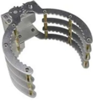
Mechanical Gripper:
The grasping is done by using mechanical fingers actuated by mechanism. In mechanical grippers, Fingers are also called as jaws. If fingers are of attachable type they can be detached and replaced. It requires certain power to actuate so the power input are pneumatics, mechanical, electric and hydraulics. There are two types of gripper mechanisms pivoting movement and linear or translational movement. In pivoting movement the gripper fingers rotate about fixed pivot point for making the gripper open and close. Generally the motion is done by some kind of linkage mechanisms. In linear or translational movements the gripper fingers open and close by
moving parallel to each other. Generally the motion is accomplished by means of guide rails so the finger base slides along the guide rail during the movements of opening and closing.
Fig 3: Mechanical Gripper Actuators
[image:2.595.334.497.387.572.2]International Journal of Innovative Technology and Exploring Engineering (IJITEE) ISSN: 2278-3075, Volume-8 Issue-7, May, 2019
Sensors
It is used to fetch information about the internal state of the robot arm and sends control signal to the controller. It can be active or passive sensors which measures environmental energy entering the sensor or emit environmental energy into the environment.
Controller
It provides necessary intelligence to control the manipulator and actuators. It also process the sensors information using many algorithms and gives control commands for the actuators to perform specific tasks.
Operation
It moves in three perpendicular direction to construct x, y, z axes. X-axis represents left and right motions. Y-axis represents forward and backward motions. Z-axis represents up and down motions. They are also known as rectilinear or gantry robots. It is a simple kinematic model having rigid structure with higher accuracy and repeatability. It has mainly rectangular work volume.
2.1.3 ACTUATORS
[image:3.595.316.514.156.355.2]Actuators are output device which provides motion based on the control signal received from the controller. The commonly used actuators are DC motor. DC motor are used in many applications such as Lathe machines, Weaving machines, Conveyors, Centrifugal pumps etc.
Fig 5: DC Motor
CONTROLLER
The controller used is Raspberry pi 3 which is used for automation of machine packing system. There are two types of models in Raspberry pi such as Model A and Model B. Model A will consume consume less power and does not requires ethernet cable. Model B consumes high power and requires ethernet cable. The hardware components of
[image:3.595.80.238.482.666.2]Raspberry pi 3 includes RAM, CPU, GPU and Ethernet port. It has also interfaces for communication with external devices. For high storage SD flash memory cards are used. The SD card contains Linux OS. It also has powered USB hub and internet connection port. SDRAM has 256MB for Model A and 51MB for Model B. It is generally a smaller pc having ram of about 512MB or 256 MB.
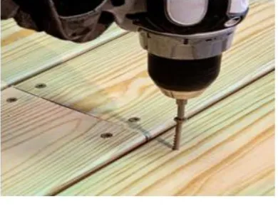
Fig 4: Cartesian Robot 2.1.4. SCREWING
Screwing is done on the cardboard box to close the wooden box so that the machine is safe. Screwing is generally done by using pneumatic fasteners on the four sides of the cardboard box. The pneumatic fasteners are held by the robotic arm to completely automate the packing process. Pneumatic fasteners are also called as nail gun or pneumatic torque wrench. It has a gear box that is fitted to pneumatic torque motor. The gear box are used mainly to absorb torque and allows the pneumatic gun to operate with the minimum effort. The torque output is adjusted by controlling the air pressure. The advantage of using the pneumatic torque wrench is it has less vibration and only minimum effort is needed so that it is
easy for the robotic arm to carry the pneumatic gun.
Fig 7: Pneumatic fasteners
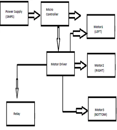
[image:3.595.329.524.570.715.2]2.2. BLOCK DIAGRAM
The figure 8 shows the sequence of working of the Automatic Machine Packing system
Fig.8. Block diagram
3. ASSEMBLY DIAGRAM
[image:4.595.50.249.96.317.2]Assembly drawing show how different parts go together, identify those parts by number and have a parts list often referred as a bill of materials. In a technical service manual, this type of drawing may be referred as an exploded view drawing or diagram
Fig 9: Assembly drawing
III. RESULT&DISCUSSION
The material chosen and the calculation done are suitable for extreme condition of load. For the control of the automatic Machine Packing System for Atta Kneader,
programming was done using ATmega328P
Microcontroller.
Fig 10 shows the Isometric diagram of Automatic Packing System for Atta Kneader
[image:4.595.347.567.151.348.2]The automation in this packing process provides more flexibility to the user. This system is user independent. The placing of machine inside the wood and cardboard box and screwing the wooden box is completely automated. At last the screwing is done by pneumatic fasteners. This setup is simple, cost efficient and covers large volume so it is very easy to pick machine and place at the required position.
Fig 10. Isometric iagram
IV. CONCLUSION
The automatic machine packing system has been successfully designed by implementing the concepts involved in mechanical, electrical and control systems. The whole process is controlled by microcontroller which receives input signal and provides output signal to actuator which is mainly DC motor. It provides a fundamental building block of many computerized fabrication tools with Cartesian motion in a simple and adaptable format.
From the experimental results it has been seen that production rate has been increased with decreased cycle time. The man power and the capital to the labours have been reduced completely. The packaging machine can able to pack 20 machines for one hour which are definitely higher than the manual packaging.
ACKNOWLEDGMENT
[image:4.595.46.263.425.688.2]International Journal of Innovative Technology and Exploring Engineering (IJITEE) ISSN: 2278-3075, Volume-8 Issue-7, May, 2019
REFERENCE
1. “Automated Packing System –A System Engineering Approach” by Paul
F. Whelan, Bruce G. Batchelor in The Institute of Electrical and Electronics Engineers on September 1996 suggested geometric packer and heuristic packerA geometric packer (GP), based upon the principles of mathematical morphology and which takes an arbitrary shape in a given orientation and puts the shape into place, in that orientation (Whelan and Batchelor 1991). (b) An heuristic packer (HP), which is concerned with the ordering and alignment of shapes prior to applying them to the geometric packer. This component also deals with other general considerations, such as the conflicts in problem constraints and the measurement of packing performance.
2. “A Depth Sensor to control Pick And Place Robots For Fruit Packaging” by
Pavel Dzitac, Abdul Md Mazid in The Institute of Electrical and Electronics Engineers on March 2013 suggested automatic packing can be done using pick and place robots.
3. “PLC Controlled Low Cost Automatic Packing Machine” by Shashank
Lingappa M, Vijayavithal Bongale, Sreerajendra in International Journal of Advanced Mechanical Engineering suggested automatic packing of different sized products based on PLC.
4. “The automatic packaging machine design based on reconfigurable
theory” by Zhihui Liu, Mengqi Li, Zhigang Chen, Zhiwei Lin, Xuemin Liu in International Conference on Consumer Electronics, Communications and Networks (CECNet).
5. “Automated material handling system using pick and place Robotic arm &
Image processing” by Deepak L Rajnor, A.S.Bhide in International Journal For Scientific research and development on 2014 suggested using of robot arm controlled by servo motors and image processing done by web camera.
AUTHORSPROFILE
Prof. S. Kannaki is working as Assistant professor in the Department of Mechatronics Engineering at Sri Krishna College of Engineering and Technology, Coimbatore, Tamilnadu, India – 641008. she has attained B.E, degree in Electrical and Electronics Engineering from PSNA College of Engineering and Technology, Dindigul, India in 2005 and M.E., degree in Power Electronics and Drives from PSNA College of Engineering and Technology, Dindigul, India in 2007. She is doing Research in Advanced Meter Infrastructure in Smart Grid. She has published a number of research papers in international journals and conferences and guided a number UG Scholars.
Prof. S. Jeganathan is working as a professor & Head in the Department of Electrical and Electronics Engineering at Dr. N.G.P Institute of Technology, Coimbatore, Tamilnadu, India. He has Obtained B.E, degree in Electrical and Electronics Engineering from Madras University, Chennai, India in 2000 and M.E, degree in Power System Engineering from Government College of technology, Coimbatore, India in 2013.He has Obtained Doctor of Philosophy in power system from Anna University,Chennai in 2013. He has published a number of research papers in international journals and conferences and guided a number UG Scholars
and research scholars.
Prof. S. PanneerSelvam is working as assistant professor in the Department of Mechatronics Engineering at Sri Krishna College of Engineering and Technology, Coimbatore, Tamilnadu, India – 641008. He has Obtained B.E, degree in Mechanical Engineering from Sri Ramakrishna Institute of Technology, Coimbatore, India in 2012 and M.E., degree in Engineering Design from Kongu Engineering College, Perunthurai, India in 2015. His Research interests include Mechanical Design. He has published a number of research papers in international journals and conferences and guided a number UG Scholars.
Prof. C. Prasath is working as assistant professor in the Department of Mechatronics Engineering at Sri Krishna College of Engineering and Technology, Coimbatore, Tamilnadu, India – 641008. He has Obtained B.E, degree in Mechanical Engineering from Adhiparasakthi Engineering College, Melmaruvathur, India in 2009 and M.E., degree in Production Technology from Thiagarajar College of Engineering, Madurai, India in 2013. He has published a number of research papers in international journals and conferences and guided a number UG Scholars.
Prof. L. Feroz Ali is working as assistant professor in the Department of Mechatronics Engineering at Sri Krishna College of Engineering and Technology, Coimbatore, Tamilnadu, India – 641008. He has Obtained B.E, degree in Mechatronics Engineering from Kongu Engineering College, Perunthurai, India in 2008 and M.E., degree in Industrial Engineering from
Anna University Regional Centre, Coimbatore, India in 2013.He is doing research in Welding. He has published a number of research papers in international journals and conferences and guided a number UG Scholars