FACULTY OF ENGINEERING AND SURVEYING
WIRELESS LAN BASED INFRARED REMOTE
CONTROL
A dissertation submitted by
John Michael Palmer, BTEng
in the fulfilment of the requirements of
Course ENG4111 and ENG4112 Research Project
towards the degree of
Bachelor of Engineering (Electrical & Electronic)
Abstract
Practically all consumer electronic devices in a household are controlled via Infrared Remote Controls. A Number of these consumer devices can be controlled using one Universal Infrared Remote Control.
A Smart Phone or Tablet PC with a Web Browser or an Application can be used to provide a new control interface to the Universal Infrared Remote Control. This is accomplished using WLAN communications and a Web Server built into a Universal Infrared Remote Control.
An Arduino based Prototype has been designed and built that successfully demonstrates a Wi-Fi enabled Smart Phone controlling consumer home media appliances. It also has an extra feature that provides automatic volume control.
Disclaimer
University of Southern Queensland
Faculty of Engineering and Surveying
ENG4111 Research Project Part 1 &
ENG4112 Research Project Part 2
Limitations of Use
The Council of the University of Southern Queensland, its Faculty of Engineering and Surveying, and the staff of the University of Southern Queensland, do not accept any responsibility for the truth, accuracy or completeness of material contained within or associated with this dissertation.
Persons using all or any part of this material do so at their own risk, and not at the risk of the Council of the University of Southern Queensland, its Faculty of Engineering and Surveying or the staff of the University of Southern Queensland.
This dissertation reports an educational exercise and has no purpose or validity beyond this exercise. The sole purpose of the course pair entitled “Research Project” is to contribute to the overall education within the student's chosen degree program. This document, the associated hardware, software, drawings, and other material set out in the associated appendices should not be used for any other purpose: if they are so used, it is entirely at the risk of the user.
Professor Frank Bullen Dean
Certification
I certify that the ideas, design and experimental work, results, analyses and conclusion set out in this dissertation are entirely my own effort, except where otherwise indicated and acknowledged.
I further certify that the work is original and has not been previously submitted for assessment in any other course or institution, except where specifically stated.
John Palmer
Acknowledgments
Thank you to my family, for their continuing support throughout my degree.
I would like to thank my supervisor, Dr Alexander Kist, for his guidance and advice, in supporting the project.
I am very grateful to the USQ Engineering Team for their support that they have given and providing an external mode of study.
Table
of
Contents
Abstract ... ii
Disclaimer ... iii
Certification ... iv
Acknowledgments ... v
List of Figures ... ix
List of Tables ... ix
Abbreviations ... x
Chapter 1- Introduction ... 1
1.1 Background ... 1
1.2 Requirements ... 2
1.3 Objectives ... 2
1.4 Dissertation Outline ... 3
Chapter 2 - Background and Literature Review... 4
2.1 History of Remote Controls ... 4
2.2 Current Commercial Products ... 4
2.3 User Interface ... 4
2.4 Security ... 7
2.5 Wi-Fi IEEE 802.11 Connectivity ... 8
2.6 Infrared IR Communications and Codes ... 9
2.7 Automatic Volume Control ... 10
2.8 Microcontrollers MCU ... 11
2.9 Integrated Development Environments IDE ... 12
2.10 Availability of System Components ... 12
Chapter 3 - System Design ... 13
3.1 System Overview ... 13
3.2 Microcontroller MCU and IDE ... 14
3.3 User Interface ... 16
3.4 MCU Web Server ... 21
3.5 Wi-Fi Shield ... 23
3.6 Infrared Communications ... 25
3.7 Automatic Volume Control ... 27
3.8 Power System ... 31
3.9 MCU System Pin Assignments ... 32
Chapter 4 - Implementation... 36
4.2 Prototype-2 ... 37
Chapter 5 - System and Functional Testing ... 39
5.1 User Interface ... 39
5.2 Wi-Fi Connectivity ... 39
5.3 AsyncLabs Web Server ... 40
5.4 IRMimic2 IR Learning and Sending ... 40
5.5 SPL Microphone Hardware ... 41
5.6 Automatic Volume Control Algorithm... 41
5.7 Power System and Energy Usage ... 41
Chapter 6 - Conclusion and Further Work ... 42
6.1 Conclusion ... 42
6.2 Future Work ... 42
References ... 43
APPENDICES ... 46
APPENDIX A - Specification ... 46
APPENDIX B - Requirements ... 48
B.1) System Block Diagram ... 49
B.2) Main System Requirements ... 50
B.3) System Requirements and Verification Matrix ... 51
APPENDIX C - Safety and Ethics ... 54
C.1) Risk Assessment ... 55
C.2) Assessment of Consequential Effects ... 56
APPENDIX D - Focus Group Research ... 57
D.1) Human Ethics Committee Application... 58
D.2) Human Ethics Committee Approval ... 70
D.3) Focus Group questions and user testing requirements ... 71
D.4) Results from Focus Group ... 72
D.5) Progress and Final Report ... 73
APPENDIX E - Project Management Plan PMP ... 75
E.1) PMP Methodology ... 76
E.2) Resource Planning ... 76
E.3) Project Gantt Chart ... 78
E.4) Project Risks ... 79
APPENDIX F - Source Code ... 80
F.1) Code Modification Note... 81
F.2) Main Arduino MCU ... 81
F.2.1) IR Testing ... 81
F.3) Apple iPhone/iPad... 117
F.3.1) Main Storyboard ... 117
F.3.2) AppDelegate.h... 118
F.3.3) AppDelegate.m ... 118
F.3.4) ViewController.h... 120
F.3.5) ViewController.m ... 121
APPENDIX G - Data Sheets ... 126
G.1) IRMimic2 ... 127
G.2 Microphone Sound Input Module ... 135
G.3) Wi-Fi CuHead Shield V2 ... 138
G.4) Arduino compatible Uno - Freetronics Eleven... 139
G.5) Arduino compatible Uno - Freetronics EtherTen ... 140
G.6) Arduino Uno ... 141
G.7) Arduino MEGA 2560 ... 146
APPENDIX H - Test Results ... 151
H.1) Apple IDE... 152
H.2) MCU IDE ... 152
H.3) Web Server ... 153
H.4) IR Controlling Devices ... 154
H.5) Wi-Fi Shield ... 155
H.6) Sound Pressure Level SPL Sensor ... 159
H.7) Power Consumption ... 161
APPENDIX I - Design Evaluations ... 162
I.1) Sub System Components and Tools ... 163
I.2) Project Challenges and Delays... 163
I.3) MCU and IDE Testing ... 163
I.4) IR Communications Testing ... 163
I.5) DFRobot Wi-Fi Shield ... 165
I.6) Web Server software library testing ... 166
I.7) User Interface design and testing ... 166
I.8) Apple Xcode and iPhone Application ... 166
I.9) USB to RS232 Serial communications link ... 166
I.10) Other MCU boards ... 168
I.11) Basic IR hardware setup ... 169
APPENDIX J - Self Reflection ... 173
List of Figures
Figure 1.1 - System Overview... 1
Figure 2.1 - IR Remote Controls ... 5
Figure 2.2 - A Universal Infrared Remote Control (Logitech Harmony 600) ... 6
Figure 2.3 - Vishay IR Receiver Block Diagram, (Vishay, 2003) ... 10
Figure 3.1 - System Requirements Block Diagram... 13
Figure 3.2 - Arduino Freetronics Eleven board... 14
Figure 3.3 - Arduino 2560 Mega board ... 15
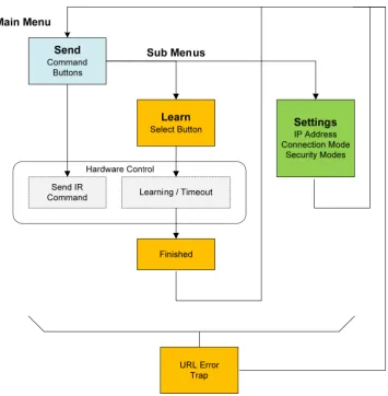
Figure 3.4 - Web Page Navigation Flowchart ... 17
Figure 3.5 - Main Web Page ... 18
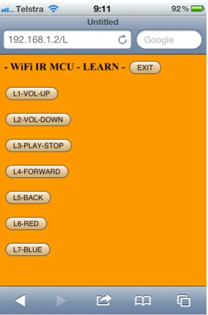
Figure 3.6 - Learn Web Page ... 18
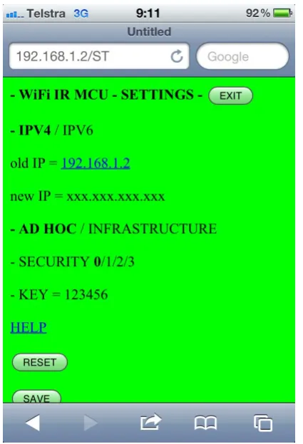
Figure 3.7 - Settings Web Page ... 19
Figure 3.8 - URL decode Error Web Page ... 19
Figure 3.9 - iPhone Application, User Interface ... 20
Figure 3.10 - LinkSprite Copperhead Wi-Fi shield V2 ... 23
Figure 3.11 - iPhone Ad-Hoc connection Settings ... 25
Figure 3.12 - IRMimic2, (Grieb, B 2012). ... 26
Figure 3.13 - Freetronics microphone module with gain feedback resistor ... 28
Figure 3.14 - DC power low pass filter and changed gain resistor ... 29
Figure 3.15 - DC power low pass filter ... 29
Figure 3.16 - Software controlled microphone circuit schematic ... 30
Figure 3.17 - Assembled software controlled microphone ... 31
Figure 3.18 - 4 x 1.2 Volt NiMH, size AA Rechargeable Batteries... 32
Figure 3.19 - Prototype-1 pin assignment ... 33
Figure 3.20 - Prototype-2 pin assignment ... 34
Figure 3.21 - Arduino Eleven IR development pin out ... 35
Figure 4.1 - Prototype-1 assembled... 36
Figure 4.2 - Prototype-2 assembled... 38
Figure I.1 - Measured IR wave forms using PC sound card ... 165
Figure I.2 - DFRobot Arduino WIZnet Wi-Fi Shield (DFRobot) ... 165
Figure I.3 - Prolific USB to Serial RS232 converter ... 167
Figure I.4 - PCMCIA Express Serial RS232 and Parallel card ... 167
Figure I.5 - AVR ISP Serial RS232 programmer ... 168
Figure I.6 - Arduino Freetronics EtherTen LAN board with 2 G SD card ... 169
Figure I.7 - IR circuit design and calculations ... 170
Figure I.8 - IR Tx Rx hardware ... 171
Figure I.9 - Freetronics EtherTen IR Pin assignments ... 171
Figure I.10 - Photodiode Trans-impedance amplifier ... 172
List of Tables
Table B.1 - Major System Requirements with Sub Requirement descriptions ... 50Table B.2 - System Requirements and Verification Matrix ... 51
Table C.1 - Hazard, Risk Identification, Evaluation and Risk Controls ... 55
Table E.1 - Project Gantt Chart ... 78
Abbreviations
The following abbreviations have been used throughout the text.
AC Alternating Current AGC Automatic Gain Control
AVR Atmel MCU
CIR Consumer Infrared
DC Direct Current
DVD Digital Video Disk
HTTP Hypertext Transfer Protocol
I2C Inter Integrated Circuit, two wire communication bus
IC Integrated Circuit
IDE Integrated Development Environment
IEEE Institute of Electrical and Electronic Engineers IR Infrared
IrDA Infrared Data Association LAN Local Area Network
MCU Microcontroller
NATA National Association of Testing Authorities NiMH Nickel Metal Hydride, rechargeable battery
PIC Microchip MCU
POE Power over Ethernet PWM Pulse Width Modulation
RoHS Restriction of Hazardous Substances Directive, European Union Shield Arduino stackable board
Sketch Arduino code file
SPI Serial Peripheral Interface, programming MCU SPL Sound Pressure Level
SRVM Requirements and Verification Matrix
TCP/IP Transmission Control Protocol / Internet Protocol
USART Universal Synchronous Asynchronous Receiver Transmitter USB Universal Serial Bus
WAP Wi-Fi encryption
WEP Wi-Fi encryption
Wi-Fi Wi-Fi a trademark of Wi-Fi Alliance is used to connect to WLAN WLAN Wireless Local Area Network
Chapter 1- Introduction
1.1 Background
Practically all consumer electronic devices in a household are controlled via infrared remote controls. In particular media entertainment systems have a large number of functions that are able to be controlled remotely. Consumers may have many devices and a number of Remote Controls having various functions and layouts.
ThinkFlood the makers of RedEye suggest that ‘deep down, everyone loves technology - or would, if it wasn’t so darn frustrating sometimes’ and ‘unreliable and hard to use.’ (ThinkFlood, 2012a) To ease consumer’s frustration and to make remote controls simpler, consumers are able to use a Universal Infrared Remote Control that combines a number of remotes into one.
The use of home wireless networks, Smart Phones and Tablets enabled with Wi-Fi has grown. Wi-Fi communications can provide a control link to a Universal Infrared Remote Control.
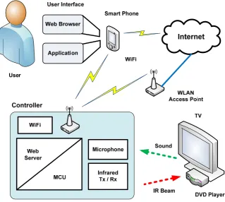
[image:11.595.167.487.428.714.2]By combining these technologies, a single control interface on an iPhone or iPad then provides a new control interface to consumer’s home entertainment systems. Or any other devices that are capable of being Infrared Remote Controlled. See Figure 1.1 - System Overview.
1.2 Requirements
The idea is to improve or extend the functionality of a consumer electronic product called the Universal Infrared Remote Control. It is extended by adding Wi-Fi connectivity and automatic volume control. The user interface is a Web Page in a Web Browser or an Application on an iPhone or iPad. User commands are sent via URL strings using standard TCP/IP HTTP protocols. See Figure 1.1 - System Overview.
The aim is to design and build a Prototype as proof of concept.
The requirements are,
Interface
o Design, with user input from research activity
o Web Pages delivered to a Web Browser
o Apple iPhone or iPad Application Wi-Fi connectivity
o Adhoc, point to point
o Infrastructure, WLAN Network
o Security modes
Web Server, on a low power Microcontroller Infrared
o Receive
o Store
o Transmit Microphone Battery power
The objectives have been broken down into major system requirements and sub system elements to satisfy a solution. These lower sub systems can be evaluated and alternatives proposed for the overall system design and Prototype.
A detailed System Requirements Block Diagram is presented in Chapter 3 - System Design. These Requirements are also linked to a System Requirements and Verification Matrix SRVM for full system testing which is listed in Appendix B - Requirements.
1.3 Objectives
The main objectives accomplished in this project include,
1. Research Infrared remote control communication, WLAN communication, protocols and hardware.
3. Design a basic Prototype for proof of concept and implement individual building blocks that include an infrared interface, WLAN hardware, Web interface and an iPhone or iPad application.
As time permits
4. Investigate Remote Control interfaces and user interaction. 5. Propose a new interface that enhances the user experience. 6. Evaluate the usability of the Prototype device.
7. Design and implement an automatic volume gain control. 8. Optimise hardware power consumption.
Overall a Prototype has been built and demonstrated showing functionality covering the objectives. A second Prototype is part of further work using a larger MCU to extend functionality. Security has been researched but not implemented due to time constraints.
1.4 Dissertation Outline
Chapter 1 - Introduction, to the background of the project, its requirements and objectives.
Chapter 2 - Background and Literature Review, relates to the information required to design the subsystems of the Prototype.
Chapter 3 - System Design, describes the subsystem components that need to be integrated into a functioning Prototype.
Chapter 4 - Implementation, presents the working Prototype and further work on a second Prototype.
Chapter 5 - System and Functional Testing, discusses testing of the Prototype.
Chapter 6 - Conclusion and Further Work, concludes the dissertation and summarises the achievements of the project with a discussion on further work required to extend functionality.
Chapter 2 - Background and Literature Review
2.1 History of Remote Controls
Remote control technology has developed over time using mechanical, wired, light, ultrasonics, wireless and infrared transmissions links (Wang, 2001). Some devices can also be controlled with the TCP/IP protocol that is used with computer networking.
Infrared remote controls are cheap and simple. As a result they are a common component used to control consumer electronic devices.
There are two main types of infrared communication protocols.
Consumer Infrared CIR for device control. For example remote control of Televisions, DVD players, Air conditioners and lights.
Infrared Data IrDA for high speed data transfer. For example pictures and video transfer between smart phones or digital cameras.
This project is only focusing on using CIR.
2.2 Current Commercial Products
At the start of this project, topic selection, there were no obvious similar commercially available products on the local market. There were hardware plug-ins for the iPhone available through online retailers. One plugged into the headphone port at the top of the iPhone called RedEye (ThinkFlood, 2012b) and others (Breen, 2010) that plug into the large port at the bottom of the iPhone.
At the time of this project appreciation report the RedEye Wi-Fi Infrared Remote Control (ThinkFlood, 2012b) and the Logitech Harmony Link (Logitech, 2012) have released a full WLAN Infrared Universal Remote Control with connectivity with iPhone, iPad and Android devices in the marketplace. The consumer electronics industry is constantly producing new products.
Although some WLAN IR remote controls are in the market there is room for improvement. Based on consumer feedback (Logitech, 2012) there is possibility of adding extra functionality or making useability simpler.
2.3 User Interface
purchasing decision determines part of the user interface design. When consumers purchase devices they do not usually read the instruction manual before making a purchase and so the interface needs to be intuitive in order for the user to like and select the product (Billingsley, 2006).
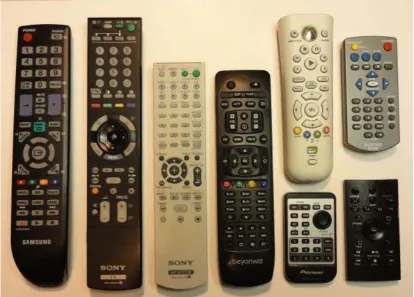
[image:15.595.120.535.188.485.2]A User Interface can have many functions. Some Infrared Remote Controls are simple and others are more complex. Looking over some Infrared Remote Controls in Figure 2.1 - IR Remote Controls, there are common controls, layouts and themes.
Figure 2.1 - IR Remote Controls
Interesting points of interest that can be used in the design are,
power on/off is at the top, ideally red in colour
a circular up/down left/right with a centre select button is common larger linked button for volume up/down, mute
larger linked button for channel up/down
media - play/stop/pause, forward, backwards, record a numeric keypad
four coloured macro function buttons
the background case colour to button colour or contrast for ease of viewing text size, colour and contrast
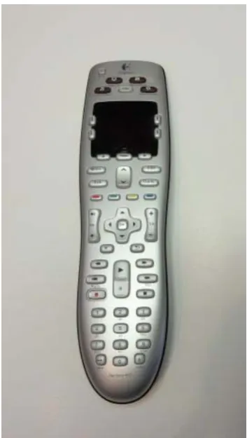
Figure 2.2 - A Universal Infrared Remote Control (Logitech Harmony 600)
One major disturbance is to look at and read a button label before an action is selected. Poor lighting on passive remote interfaces are a problem whereas an iPhone or iPad is backlit. One problem with touch screen devices is they lack tactile response (Breen, 2010). The user is unable to feel around the controls while keeping their eyes on the viewing screen to select an action.
With the popularity of the internet, smart phones and tablets now ingrained into the lives of many technology conscious consumers, an interface using these devices can now be an application (Craft & McElveen, 2010) or a Web Page. A Web Page can use HTML Cascading Style Sheet CSS to format and make the Web Page interface more appealing (Lemay, 2003). To produce Web Pages the MCU needs to include a Web Server that can serve HTML using the HTTP protocol.
So why do some controls have different shapes, sizes, surfaces and colours? How does this affect the user and what do they think about different interfaces? And what would be the best features to put into an interface? To gain more specific information about Infrared Remote Controls and how they are used a Focus Group Discussion Research Activity has been undertaken, see results in the Appendix D.
Key outcomes from the discussion group on interfaces indicated that users,
like simple interfaces that they can see and read at night in low light levels require prompting to navigate more complex navigation
most frequently use the volume and channel changing functions don’t like dealing with batteries
don’t like obstacles blocking the Infrared beam have trouble finding their Remotes
have difficulties with WLAN and computer networking
This project will use an Apple iPhone or iPad as the control interface to the WLAN Infrared Remote Control and these user interface considerations will enter into the design.
2.4 Security
Security encompasses the access and the control of the system. It also deals with protecting the integrity of the system from modifications and counterfeiters. There are many areas and levels of security technology.
Access to the system can be controlled with user authentication using a login to stop any unauthorised control of equipment. This could also allow for the use of ciphertext for network communications (Thomas, T 2004). A simple method of encryption is to use the logic XOR function with a key to produce ciphertext (ELE3305, 2009). Higher level software methods use built in mature security modules like Microsoft DotNet that bind to Event controls (Freeman & Jones, 2003). These advanced methods are not designed for microcontrollers, however they may work with the Microsoft embedded Operating System and needs to be researched further.
Protecting product design, patents and market share is very important (Codan, 2012). Protecting the code inside the MCU from being copied is of concern. Correct MCU selection can guard against copy protection attacks and competitors reverse engineering the design by ripping firmware (Skorobogatov, 2000/2004). MCUs contain a fuse bit that when burnt out or set prevents the flashed code from being read out. This can overcome by copiers by dissolving the package and reading the memory optically direct from the surface of the IC chip. Here the MCU manufacture Atmel backs up this claim.
‘Robust data security is absolutely essential in today's information-critical business environments. But standard memories and conventional storage often don't provide enough protection.’ (Atmel, 2012a).
Atmel MCUs are now available with a metal guard over the memory at the silicon level to stop memory contents being read optically.
Atmel offers a hardware chip set for authentication, the AT88SA10HS/102S devices. The AT88SA102S is designed to be embedded in the product with an embedded 265bit key. It uses SHA-256 and responds with a unique response when sent a challenge. (Atmel, 2012b)
As encryption and security is a large complex area of knowledge this will be implemented last if time permits.
2.5 Wi-Fi IEEE 802.11 Connectivity
A Wireless Local Area Network WLAN allows connection and data transfer between computing devices. The different IEEE 802.11 standards ensure different devices can connect without problems. This project is concerned only with the 802.11 b/g/n modes that the iPhone 4 (Apple, 2012b) and iPad 2 (Apple, 2012c) can both support.
The MCU needs to support 802.11 b/g/n connectivity. It is anticipated that only small amounts of data will need to be sent, so the throughput speed is not critical. There will need to be a balance of data throughput and power consumption with a power sleep mode to maximise battery life. There are a number of different manufactures for Arduino Wi-Fi Shield modules with Wi-Fi connectivity they are,
DFRobot, 802.11b 11, 5.5, 2, 1 Mbps (DFRobot, 2012) CuHead Wi-Fi Shield 802.11b 1, 2Mbit/s (CuteDigi, 2012)
There is a software library (AsyncLabs, 2012a) and examples (AsyncLabs, 2012b).
Connection Mode can be either,
AdHoc - point to point
Infrastructure - through a network
Wi-Fi Security modes,
No security
WEP, Wired Equivalent Privacy WPA, Wi-Fi Protected Access WPA2, Wi-Fi Protected Access 2
2.6 Infrared IR Communications and Codes
Codes
For the WLAN IR Remote Control to control multiple electronic consumer devices it needs to use CIR Standards. The big problem is there is no real common standard for CIR. This is because the CIR control of devices has evolved over time from early days and it was not until interference between devices became a problem that something was done. Big name manufactures have implemented their own Standards. Adding to the complexity, each manufacture has varying code types that have evolved over time.
There is a large variety of IR modulation signals associated with commands. They are well documented by Bergmans (2012) and Shirriff (2009). This adds some decoding and algorithm complexity to the project. Common IR codes include (Vishay, 2003),
Phillips RC5, RC6 NEC
SONY
Toshiba Micom Format Sharp
RCMM
R-2000 RECS-80
Raw waveform
One way to overcome the decoding of the modulation signals is to store the captured signal as a raw waveform and then retransmit it when required. One drawback to this is more memory is needed in the MCU (Shirriff, 2009).
A deicated IC that can store up to 57 IR codes/waveforms and play them back is IRMimic2 PIC IC by Tauntek (Grieb, B 2012) and identified by AVRFreaks as a reliable solution (AVRFreaks, 2012).
Carrier Frequency
Infrared Transmission
An Infrared IR Light Emitting Diode LED look like a common LED but their output wavelength is invisible to humans. Some have a clear or blue moulded casing with a lens. The spectral wavelength required is 940 nm known as Far Infrared. IR LEDs have expected bandwidth of 50 nm and beam angle 30 degrees with power levels of 100mW (Jaycar, 2010), datasheets (Everlight, 2004), (Taitron, 2007). For hardware testing purposes the IR spectral emission can be seen by a camera (Shirriff, 2009).
Infrared Reception
An Infrared IR Photodiode detects and receives Infrared energy levels. The device has some capacitance and its output is a current. To overcome this and to look at faster signals a trans-impedance or current to voltage converter is needed (Neamen, 2007).
Infrared receiving detectors can be interfered with or receive IR energy from other sources like sun light, fluorescent lamps and heating points. To overcome false readings of signals the bursts or pulses of IR are modulated by the transmitter. The modulation carrier frequency is commonly 38 kHz. An Integrated Circuit IC with a combined converter amplifier, filter and demodulator is available like the Vishay TSOP41xx, (Vishay, 2003). A block diagram of this IR receiver IC is in Figure 2.3 - Vishay IR Receiver Block Diagram.
Figure 2.3 - Vishay IR Receiver Block Diagram, (Vishay, 2003)
2.7 Automatic Volume Control
By the inclusion of a microphone that can pick up the sound pressure level in the room the MCU software can then send volume down and up commands based on a hysteresis type algorithm. It is intended that this optimisation of the algorithm will require some trial and error testing.
A microphone hardware module by Freetronics is available and could be adapted for the Prototype (Freetronics, 2012). By using an 8-channel analogue multiplexer / demultiplexer 4051 IC the gain can be digitally controlled through software (delabs, 2005).
2.8 Microcontrollers MCU
A kit called ‘WIB Web server In a Box’ supplied by Silicon Chip (Grassi 2009). This kit has been built and tested by the Dissertation Author. It contains a PIC MCU running a TCP/IP wired LAN interface and Web Server. Performance is not the same as a PC however it is a low power solution and a proof of concept that a MCU can be used for this project.
Microcontroller selection will consider a number of important factors,
Hardware specification
o Number of Inputs/Outputs and type, Analogue, Digital, PWM
o Internal timers
o Register sizes
o UARTs
o Memory size and speed
o Operations optimization
o Availability
o Environmental like vibration and temperature ranges
o Low power requirements, sleep modes Cost of both hardware and firmware development Reliability, and life span
Programming IDE and firmware programmer Operating system / boot loader
Security of embedded firmware Power requirements
Environmental product support
2.9 Integrated Development Environments IDE
Both Atmel AVR Studio 5 (Atmel, 2012c) and Microchip MPLAB v8.66 (Microchip, 2012) are professional MCU IDEs which are free to use. Optional optimising C compilers and programming modules for in-system debugging are available at extra cost.
The Arduino MCU IDE version 1.0 is more simplified with only the most basic features suited mainly for hobbyists. It supports the AVR MCU and supports a large number of plug in modules from many different manufactures using a common header pin out (Arduino, 2012). There is also an Arduino based board with a PIC MCU available. Arduino boards mostly contain the AVR MCU and the code can also be written and compiled using Atmel AVR Studio (EngBlaze, 2012).
The Apple iDevice IDE Xcode can be downloaded and used on an iMac. A developer fee of $99 per year is required and the developer must be registered. iDevices are linked to the developers registration and software can only be deployed to the registered iDevices (Apple, 2012a).
2.10 Availability of System Components
The supply and availability of components required to build a Prototype at low cost can be restrictive. Integrated Circuit and MCU Chip manufactures take minimum orders by the 1000’s. The Atmel and Microchip PIC MCU manufactures produce development kits that support their parts. Other single purchase of components may be available through retailers at added cost.
Companies and part availability can come and go in months. A large company ‘Microchip was ranked No.4 after Atmel, which climbed to No. 3 from No. 5’ and Steve Sanghi, Microchip CEO ‘recently bought Roving Networks, a Calif-based company providing Bluetooth and Wi-Fi modules and solutions’ as of 7th May 2012 (Yoshida J, 1012) This may have affected the supply of some types of Arduino Wi-Fi Shields.
Parts also include software systems and libraries. Software changes and updates are not always backward compatible to previous components. The Arduino and MCU open source community along with forums is rich with applied knowledge that solves these problems. (Arduino, 2012) (AVRFreaks, 2012)
Chapter 3 - System Design
3.1 System Overview
The design is broken into modules. Modules that pass testing form the Prototype. The production of an embedded system MCU Design and methodology is discussed by Leung (2012)
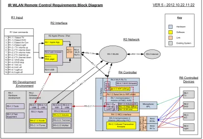
The overall design for the Prototype is best managed by defining each requirement that is easily referenced. These requirements are modelled into a system block diagram for a system overview. Each subsection has been designated a requirement number with sub-requirements. This is mostly fine grained with a lot of detail, see Figure 3.1- System Requirements Block Diagram. Or for a larger view see Appendix B. This has been done for full system testing and is tracked using a System Requirements and Verification Matrix SRVM also listed in Appendix B.
R3-1 WLAN
R6-3 A/C R6-1 TV R1 User commands
IR WLAN Remote Control Requirements Block Diagram
R4 Controller
VER 5 - 2012.10.22.11:22
R1-1.1 Select TV R1-1.2 Select DVD R1-1.3 Select Air Con R1-1.4 Select Light R1-2.1 TV volume up R1-2.2 TV volume down R1-2.3 TV volume mute R1-2.3 TV channel up R1-2.3 TV channel down R1-3.1 DVD play R1-3.2 DVD stop R1-4.1 A/C on R1-4.2 A/C off R1-5.1 Light on R1-5.2 Light off
R2-3 HTTP R2-1 Apple App
R2-2.1 Web page R2-4 Wi-Fi Rx/Tx R4-5 IR Rx R3-1.1A R 3-1.4 R4-6
IR Tx R6-4Light R6-2 DVD Hardware Software Key R1 Input
R4-1 microprocessor 1
R4 -3 Ba tte ry R4 -2 .3 Dig ita l Ou t
R4-1.5 Web Server
R4-2 microprocessor 2 R4-1.2 Serial link to WiFi shield
R4-1.3 MCU interface
R4 -2 .2 Di g ita l In Link
R4-2.1 Infrared Transceiver firmware
Existing System R3 Network
R6 Controlled Devices
R4-4.3 WiFi settings R4-4 Wi-Fi Rx Tx
R4-4.1 Wi-Fi firmware
R4-1.1 USB to UART R5-2.2.1 USB R5-2.2.1.1 R4 -4 .2 ju m per R5-2.2.2 WiFi R3-1. 3 R5 Development Environment
R4-1.6 IR cmd R4-1.4 Arduino OS R2 Interface 1 2 3 4 5 6 7 8 9 10 11 12 13 14 15
R2 Apple iPhone / iPad
R2-2 web browser
IRMimic (Microchip PIC) Arduino (ATMEL AVR)
[image:23.595.119.534.340.624.2]R2-5 USB R 5-2.1. 1.1 R5-2.2 Microsoft R5-2.1 Apple R5-2.1.3 Xcode R5-2.2.3 Arduino R5-2.1.1 USB R5-2.1.4 iTunes R5-2.2.4 Terminal R3-1. 2 R5-2.1.2 LAN R3-2 Internet R3-1.5 R4 -1 .4 RA M R5-2.2.5 WizNet R5-1.2 Test Equipment R5-1 Hardware development R5-2 Software development R5-1.1 Tools R3 -1.1B Microphone SPL
The Prototype hardware design includes, Wi-Fi, Infrared receive store and transmit, microphone, a control MCU with Web Server, and a battery.
The final stages of the software design includes, IR code learning and sending, Wi-Fi connected Web Server with HTML Web Pages, an iPhone or iPad Application, factory software reset, user settings and a software controlled microphone gain. A discussion group and user testing was performed to provide feedback on the design. Security needs to be implemented.
Overall this project uses a number of relatively mature technologies that are integrated into the Prototype solution.
3.2 Microcontroller MCU and IDE
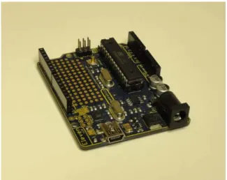
The Microcontroller MCU selected for Prototype-1 is the Arduino Atmel AVR328p. It is an 8 bit 16 MHz MCU with 2 k SRAM, 32 k Program memory and just enough I/O to test concept. The Arduino board contains a power regulator and an onboard USB to serial programmer. The Arduino platform has been designed for rapid prototyping. Arduino has set a standard for its header pin out which has been used with pluggable boards called Shields to add functionality to the project. See Figure 3.2 - Arduino Freetronics Eleven board.
[image:24.595.164.490.434.692.2]
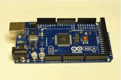
After initial testing it has been determined that the Web Server needs more SRAM for its runtime variables. Without making too many changes to the initial design a second MCU board is still being worked on for Prototype-2 to extend the base functionality. The Arduino 2560 Mega has 8 k SRAM and a further 256 k Program memory with more I/O. It is the next higher equipped Arduino development board, see Figure 3.3 - Arduino 2560 Mega board.
Figure 3.3 - Arduino 2560 Mega board
Both the Arduino hardware MCU boards are supported by the Arduino Integrated Development Environment IDE for writing of the software code and downloading the compiled files into the MCU. The code is written in C and uses Arduino variables and functions. The higher level C programming language is a better choice to code higher levels of functionality and software complexity for the project.
The Arduino platform supports many hardware shields with corresponding libraries extending purpose fit functionality. The Arduino IDE works on both the Microsoft Windows and Apple Operating Systems. The project has used the Microsoft Windows Arduino IDE version. Migration of MCU code from Arduino IDE to AVR Studio IDE is possible but has not been done.
The Arduino platform advantages include,
local MCU board, parts and shield availability various Wi-Fi modules available
code examples
3.3 User Interface
From the research of common controls and their layout a user interface design can be created. Feedback from the user discussion group including control usage patterns suggests a simple design is a good starting point. Based on these considerations a simple basic test interface to control a portable DVD player will contain,
volume up volume down play / stop forward back on/off, red other, blue
The Web Page interface will be driven by the MCU Web Server that can post simple HTML text strings and get HTTP URL requests for commands. Some nicer simple web page design can be managed by using HTML, CSS and picture icons (Lemay, 2003). A full icon driven interface can be used instead of text with an advantage of being user language independent.
Figure 3.5 - Main Web Page
[image:28.595.225.431.422.733.2]Figure 3.7 - Settings Web Page
[image:29.595.223.431.435.741.2]Applications for the Apple iPhone / iPad are written in Apple Objective C syntax (DeVoe, 2011) using the Apple Xcode IDE. The setup, development and application installation process is well described by iPhone Game Development (Craft, & McElveen, 2010) with further information on the Apple Developer web site. The registration process requires acceptance of the licence agreement with Apple. To use the IDE a yearly fee is required and the developed software can only run on apple devices registered to the developer’s key. The key has to be backed up on a USB drive. There are different levels of developer contract with Apple based on software functions and services used. In order to have the application submitted in the Apple App store the hardware needs to be submitted to Apple and kept by Apple at cost to the developer. Any change to the hardware or software means the device has to be resubmitted to Apple.
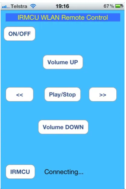
[image:30.595.223.432.280.592.2]A simple Application written for the iPhone 4 is in Figure 3.9 - iPhone Application User Interface.
Figure 3.9 - iPhone Application, User Interface
Further work would include using images to replace the buttons and the use of swipe controls. Also security by user authentication needs to be implemented and would form part of the Settings Web Page asking the user for a password to access the system.
3.4 MCU Web Server
The Web Server is central to the design as it provides the interface. It is an integrated component of Wi-Fi hardware. The Wi-Fi AsyncLabs Web Server Library is used. It has a different Library and has different functionality than the tested Freetronics EtherTen LAN Web Server.
The Library files are downloaded from GitHub repository. For the WiShield, AsyncLabs has to abide by the terms in the license for the driver code ‘g2100’ for the Wi-Fi module, which is provided by ZeroG Wireless Inc.
The files are then installed by performing a copy and paste of the WiShield folder into the Arduino IDE libraries folder.
The MCU Code for the Web Server calls is examined in the next few blocks of text with example code fragments.
On start up the Web Server needs to be initialised and told where to find the Web Page to send to the Web Browser.
void setup() {
. . .
//--- Enable Serial output and ask WiServer to generate log messages (optional)
WiServer.enableVerboseMode(true);
//--- Initialize WiServer and have it use the sendMyPage function to serve pages
WiServer.init(sendMyPage); .
. . }
The main MCU code loop has to call the Web Server to keep starting as it will not be running after it has done its processing. The loop delay also needs to be increased to cater for more URL decoding, but not too much.
void loop() {
WiServer.server_task(); //--- Run WiServer .
. .
The Web page HTML strings are printed from program memory and processing of received URL commands after a number of packets has finished being sent. See the next example code fragment.
boolean sendMyPage(char* URL) {
. .
// check if Web Page has been sent, as it is a number of packets if(>appstate.ackedCount) && (0==(int)uip_conn->appstate.sentCount)) // is ready
. . .
//---VOLUME UP command ---
else if (strcmp(URL, "/S1") == 0) //SEND button 1 {
//Serial.println("URL=/S1"); //VOL UP
IR_CSEL(1); //select memory location number 1 IR_SEND(); //send IR pulse train
} .
. .
//finish URL processing calls, now send web pages
// Home web page
if (strcmp(URL, "/") == 0) // just IP address of home page {
// write page content from flash memory webpHOME();
WiServer.print_P(flash memory HTML text string); return true; } . . . }
The ASYNCLABS apps-conf.hLibrary needs to be edited to define the variable APP_WISERVER
. . .
// Filename: apps-conf.h
// Description: Web application configuration file . . . #define APP_WISERVER . . .
3.5 Wi-Fi Shield
After initial evaluation testing of the DFRobot Wi-Fi Shield, the Copperhead Version 2 Wi-Fi Shield was selected. See Figure 3.10 - LinkSprite Copperhead Wi-Fi shield V2.
The Copperhead Version 2 Wi-Fi Shield meets the design requirements of,
Wi-Fi mode 802.11b 2.4 GHz
Connectivity modes of Adhoc and Infrastructure Security options, none, WEP, WAP, WAP2 Data communication using the TCP/IP layer Software Library
Other specifications include (CuteDigi, 2012), rechargeable battery circuit
16 Mbit serial flash, good for storing Web Pages 1Mbps and 2Mbps throughput speeds
Low power usage
[image:33.595.163.489.441.684.2] Sleep mode: 250μA, Transmit: 230mA, Receive: 85mA Microchip Wi-Fi module
Figure 3.10 - LinkSprite Copperhead Wi-Fi shield V2
. . .
#define WIRELESS_MODE_INFRA 1 #define WIRELESS_MODE_ADHOC 2
// Wireless configuration parameters --- unsigned char local_ip[] = {192,168,1,2}; // IP address of WiShield unsigned char gateway_ip[] = {192,168,1,1}; // router or gateway IP address unsigned char subnet_mask[] = {255,255,255,0}; // subnet mask for the local network const prog_char ssid[] PROGMEM = {"IRMCU"}; // max 32 bytes
unsigned char security_type = 0; // 0 - open; 1 - WEP; 2 - WPA; 3 - WPA2
// WPA/WPA2 passphrase
const prog_char security_passphrase[] PROGMEM = {"12345678"}; //max64 characters
// WEP 128-bit keys // sample HEX keys
prog_uchar wep_keys[] PROGMEM = { 0x01, 0x02, 0x03, 0x04, 0x05, 0x06, 0x07, 0x08, 0x09, 0x0a, 0x0b, 0x0c, 0x0d, // Key 0
0x00, 0x00, 0x00, 0x00, 0x00, 0x00, 0x00, 0x00, 0x00, 0x00, 0x00, 0x00, 0x00, // Key 1
0x00, 0x00, 0x00, 0x00, 0x00, 0x00, 0x00, 0x00, 0x00, 0x00, 0x00, 0x00, 0x00, // Key 2
0x00, 0x00, 0x00, 0x00, 0x00, 0x00, 0x00, 0x00, 0x00, 0x00, 0x00, 0x00, 0x00 // Key 3
}; // setup the wireless mode
// infrastructure - connect to AP
// adhoc - connect to another Wi-Fi device
unsigned char wireless_mode = 2; //WIRELESS_MODE_ADHOC;
unsigned char ssid_len;
unsigned char security_passphrase_len;
// End of wireless configuration parameters --- .
. .
Figure 3.11 - iPhone Ad-Hoc connection Settings
This part of the design provides the Wi-Fi connectivity.
3.6 Infrared Communications
Initial design evaluation testing using an Arduino IR Library, Vishay receiver and an IR Tx LED was not 100% successful. Two identical back to back IR receive store transmit systems were setup. It was found that problems were mainly in reliably decoding and transmitting IR signals. Even though the library displayed consistent decoding results, the output waveforms varied. The same system that decoded and transmitted a signal could not then do the same back, see Appendix Test results. Receiving, storing and transmitting the raw IR signal was successful. The next design problem was to store even longer IR signals as used with the Microsoft Xbox 360. At this stage in the project time was extended and ran out. This further work was left to time availability on Prototype-2.
Figure 3.12 - IRMimic2, (Grieb, B 2012).
The MCU mode is set by setting pin 23 MDE low with a 470 ohm resistor on power start up.
The IRMimic2 MCU control lines are,
CSEL 0-5, 0-56 command memory locations LRNRQ, learn request
LRNERR, learn error SNDRQ, send request RDY, ready
Data Sheet and circuit diagram is in Appendix G.
Arduino MCU code example for learning an IR signal
. . .
// select a channel in IRMimic2 MCU memory
// set channel pins if (2==CSELset) {
Serial.println("2==CSELset");
digitalWrite(pin_IRMimic2_CSEL_0,LOW); digitalWrite(pin_IRMimic2_CSEL_1,HIGH); digitalWrite(pin_IRMimic2_CSEL_2,LOW); }
. .
void IR_LEARN() {
.
// Manage IRMimic2_LearnErrors .
// make LRNRQ = HIGH (learn)
// then RDY = LOW and IRMimic2 LED will light digitalWrite(pin_IRMimic2_LRNRQ, HIGH);
// using Timer 0 //wait for IRMimic to be ready about 2 ms delay(3);
// Hold IR remote to Vishay receiver and push button to be learned
// Manage a Timeout
digitalWrite(pin_IRMimic2_LRNRQ, LOW); Serial.println("IR_LEARN finished"); . . . }
Arduino MCU code example for Sending an IR signal is similar.
. . .
// select a channel in IRMimic2 MCU memory .
. .
digitalWrite(pin_IRMimic2_SNDRQ, HIGH);
// Manage a Timeout for hardware errors
digitalWrite(pin_IRMimic2_SNDRQ, LOW);
Serial.println("IR_SEND finished");
}
This presents the IR design.
3.7 Automatic Volume Control
By including into the design a microphone, an average Sound Pressure Level SPL can be measured and used as part of a feedback loop to control volume. This is like an Automatic Gain Control AGC system. This automated adjusting of the volume is planned for use on a separate sound amplifier for a Television media centre. In this way no animated volume bars are seen on a Television screen. Some Televisions may be able to turn off the animated on screen volume bars and the Prototype could directly control the Television volume unit.
The design concept is to only increase the volume up to 3 times and then lower it down to 3 times while keeping track of the volume position. The sound levels are not measured in any calibrated way. It is just met to increase and decrease around what the individual user would consider their personal average volume listening level.
The hardware listens and if the SPL is above a threshold code immediately decreases the volume one time. The algorithm listens again and reduces the volume one more time if the measured SPL is above the set threshold. To increase the volume the system listens and if the room sound level is quieter with the SPL below the threshold for about six seconds, an IR signal is sent to increase the volume.
The SPL threshold level is set by adjusting the gain on the microphone R4, 1 MΩ. Initially the gain was set manually by some rough op-amp gain calculations and then by trial and error. Finally a gain feedback resistor of 220 kΩ proved a good value for testing and can be seen hand soldered in place of the surface mount resistor in Figure 3.14 - DC power low pass filter and changed gain resistor. See Figure 3.13 - Freetronics microphone module with gain feedback surface mount resistor. The SPL output is used and has a small RC time constant, see Freetronics Microphone circuit schematic in the Appendix G - Data Sheets.
Figure 3.13 - Freetronics microphone module with gain feedback resistor
Figure 3.14 - DC power low pass filter and changed gain resistor
[image:39.595.193.462.88.430.2]The filter uses a low Q ferrite bead inductor, 220 ohm resistor, 470 μF, 25 V capacitor. This produces a measured 0.28 Volt drop on the supply rail for the Microphone circuit. The RC time constant is 103 ms and the ferrite bead should reduce high frequency components as it shouldn’t be saturated with current. This circuit could be refined with further analysis and measurements as future works. Overall the DC power filter works well, see Figure 3.15 - DC power low pass filter.
Due to a longer overall response time taken to process a volume send command. The command is sent twice in the Arduino MCU code and works well.
There is a need for the user to be able to adjust this gain. This can be done through the user interface by using software to control the Microphone gain and set a SPL threshold. The hardware implementation is performed with a 4051 Multiplexer / Demultiplexer IC being a digitally controlled analogue switch. See Figure 3.16 - Software controlled microphone circuit schematic.
150 kΩ
47 kΩ
47 kΩ
47 kΩ
47 kΩ
47 kΩ
47 kΩ
47 kΩ
A B C 11 10 9 3 Vin 13 14 15 12 1 5 2 4 16 6 7 8 4051
+ 5 Volt
Vout
1 MΩ
[image:40.595.165.481.242.565.2]feedback
Figure 3.16 - Software controlled microphone circuit schematic
Figure 3.17 - Assembled software controlled microphone
3.8 Power System
The Arduino standard has a 2.1 mm power socket that accepts a DC input of +7 to +12 volts which can be powered from a mains AC power plug pack. The board can also be powered from the USB +5 volt serial cable. USB power is used during software development.
The inputs are regulated by an onboard power converter supplying the common power header with,
+5.0 V, 200 mA +3.3 V, 50 mA
unregulated input voltage
The Atmel AVR 328p MCU output pin rating is 5 V at 40 mA.
Power usage is important. The Arduino main MCU has a low power sleep mode. Parts of the circuit should be switched off when not in use. The Wi-Fi Shield is power hungry however it supports a power saving sleep mode. Power saving actions also includes managing unused pins and circuit functions (STMicroelectronics, 2012). Power saving features have not been enabled, it is further work for Prototype-2.
‘The IR sensor module requires a small amount of operating current whenever it is powered. For good battery life, it is necessary to power down the IR sensor module except when learning. The IR Mimic2 chip handles this automatically.’ (Grieb, 2012). CuHead Wi-Fi shield power consumption specifications
o Sleep mode: 250 μA
o Transmit: 230 mA
o Receive: 85 mA
The systems total average current will be measured in the results section and will give an indication of battery life.
A 6 volt 4 x 1.5 Volt size AA Alkaline battery connected directly to the 2.1 mm power socket will under power the MCU. This battery will need to be connected through a silicon power diode to the +5.0 Volt power header pin.
To keep the voltage down Prototype-1 will use 4 x 1.2 Volt NiMH cells with the total supplied voltage about 4.8 Volts. This will drop as the battery loses its charge. Figure 3.18 - 4 x 1.2 Volt NiMH, size AA Rechargeable Batteries
Figure 3.18 - 4 x 1.2 Volt NiMH, size AA Rechargeable Batteries
3.9 MCU System Pin Assignments
Figure 3.19 - Prototype-1 pin assignment
AREF GND LED 13 12 PWM 11 PWM 10 PWM 9 8 7 PWM 6 PWM 5 4 PWM 3 2 TX 0 1 RX 0 0 0 1 2 3 4 5 RESET 3V3 5V GND GND VIN ANA LOGU E POWER D IGI TAL
Arduino MEGA 2560 Pin Out
Reset Settings
WiFi INT 0 WiFi Status LED
Wi F i SCK Battery + -Reset MCU 8 9 10 11 12 13 ANALO G UE 6 7 14 15
TX 3 14 RX 3 15 TX 2 16 RX 2 17 TX 1 18 RX 1 19 SDA 20 SDA 21
[image:44.595.125.513.59.510.2]Wi Fi SS W iFi MI SO WiFi M O SI DIGITAL CO MM UNIC A TIO N 22 24 26 28 30 32 34 36 38 40 42 44 46 48 50 52 GND 23 25 27 29 31 33 35 37 39 41 43 45 47 49 51 53 GND SP L A SP L B SP L C
Chapter 4 - Implementation
4.1 Prototype-1
The sub system elements of the design are implemented in the first functional Prototype-1. The Hardware and Software components are listed below.
Hardware boards and Shields have been stacked together and consist of,
Infrared IRmimic2 MCU with Learn / Store / Send Factory Settings Reset Button
Wi-Fi connectivity, CuHead WiShield V2 Main MCU with Web Server
Fixed gain Microphone with DC power filter Battery Pack
[image:46.595.157.499.392.680.2]See Figure 4.1 - Prototype-1 assembled
MCU Software components consist of,
AsyncLabs Web Server simple Web Pages
Factory Wi-Fi configuration settings simple Factory Reset of IP address only simple display of Settings
limit of seven IR channels stored and learnt, max is 57 all seven IR channels can be Sent
Automatic volume enabled
serial print out for debugging and program status
Note: Software features are limited but functional due to the 2k SRAM limit of the AVR328p MCU affecting the Web Server performance. Further design work has continued on the Arduino Mega2560 MCU board that has increased resources.
User interface is functional with both the Web Browser WebPages and the iPhone Application. From user input in the Focus Group discussion research a simple interface was delivered to enhance the user experience.
Web Pages are simple and there layout is exactly as described in Chapter 3 System Design
Send Learn Settings Error
iPhone Application is also displayed in Chapter 3 System Design
one page simple buttons
one button to open Web Browser for command Learning and Settings
4.2 Prototype-2
Further work continues on with Prototype-2, it is not fully operational. It uses the Arduino Mega 2560 with 8k SRAM and more digital I/O. This allows for extending the functionality of the user interface and software controlled features
Hardware boards and Shields stack consist of,
Wi-Fi connectivity, CuHead WiShield V2 Arduino MEGA 2560 with Web Server Fixed gain Microphone with DC power filter
Battery Pack to be added, may use battery circuit on CuHead WiShield V2
[image:48.595.155.498.193.504.2]See Figure 4.2 - Prototype-2 assembled
Figure 4.2 - Prototype-2 assembled
The MCU Software is the same as Prototype-1 except for pin out changes to allow for the different MCU connections.
Chapter 5 - System and Functional Testing
This section gives details of the testing and evaluation of system components and functions of Prototype-1. Further test and evaluation results are in the Appendix.
Testing of the full system has been marked on the SRVM in Appendix B - Requirements. Appendix H - Test Results, includes pre-testing and evaluation testing leading to Prototype-1 Testing.
A Serial Terminal program was also used to check and validate correct MCU program execution.
Prorotype-1 was demonstrated during the Focus Group discussion research activity and to the project Supervisor successfully.
5.1 User Interface
Web Browser and Web Pages - The designed Web Pages all worked and were able to be viewed on a networked computer, iPad and iPhone through a Web Browser. By keeping the design to only send simple HTML text strings there were no problems in rendering the Web Pages and performance was good both through Adhoc and Infrastructure Wi-Fi connection modes. The Web Page reads the screen resolution and correctly sets the pixel width of iPhone so the Web Page text is large enough to read on large and small screens. Each button was pressed and worked. Entering other URL commands that were not in the URL decode code produced the URL Error Web Page as expected and allowed the user to navigate back to the Send Home page. Sometimes the Web Server was a little delayed in processing URL commands, but once a command was processed the following commands were quick.
iPhone Application - Touching the Application Icon successfully launched the program. Each button on the simple interface was tapped and worked. To access the other areas of the system a button in the lower left corner opened the Web Browser and allowed the system to be programmed through the Web Pages. The Application gave a more seamless integration look and feel to the system as with the Web Browser the user could see the processing activity.
5.2 Wi-Fi Connectivity
5.3 AsyncLabs Web Server
Keeping the Web Pages and Menu simple as well as limiting the amount of URL string decoding kept the Web Server stable. After setting up the AsyncLabs Library and using the Arduino IDE 0023 the Web Server was successfully implemented. If any more system variables were used the Web Server was unstable. Even though the MCU code compiled and downloaded correctly, no warnings were given. Much functionality was rolled back to make the Web Server stable.
To process URL commands the code needed to test when the server response had finished. Supporting documentation indicating how to do this did not work and when the Library was opened the code had a comment noting that it was unfinished and not coded. This may have been a regression bug in the Library as other online sources indicated that it does work. The Library was the only version available on GitHub. This needs further investigation.
It is critical that the Web Server be sorted out for further functionality to be extended as the whole system relies on it.
5.4 IRMimic2 IR Learning and Sending
Testing of the IRMimic2 chip was successful on all the home media devices and air conditioner except for the XBox360. This Xbox360 results is supported by Shirriff (2009). The length of IR codes for an Xbox360 is longer than the codes for the tested Sony Amplifier and TV. The IRMimic2 chip cannot store the longer Xbox360 IR codes and this part of the project will need further work.
The IRMimic2 chip easily learnt IR signals. The LED indicator helped the user know when the IR code had been learnt. There were a few minor attempts to improve the learning of the volume commands as they were repeat codes. The user had to press the sending volume code quickly and not hold the button down, that’s all. This learning setup information would have to be added to the user manual. Overall the IRMimic2 chip worked very well.
On power up some times the IRMimic2 chip would start up in learning mode and overwrite a memory location. The possible cause is the SRAM limit on the Arduino, because when functionality was reduced by reducing program variables the problem seemed to disappear. Further investigation of the start up states of the Arduino pins is required along with using some professional MCU IDE tools.
5.5 SPL Microphone Hardware
The added DC low pass filter stops the digital noise and the analogue circuit works well. Tapping the microphone lit the green LED indicating the SPL threshold was being reached. A louder volume of sound was adjusted coming from a Television and then a music player. The SPL threshold was triggered and gain was about right.
5.6 Automatic Volume Control Algorithm
Prototype-1 was left running for about two hours listening to room SPL from commercial Television showing advertising and also movie content. The volume up command was sent allowing the volume to increase to the SPL threshold. Then the volume down command was sent for sound levels above the SPL threshold. When people entered the room to make conversation the volume automatically lowered as people tried to talk above the sound of the Television. The volume lowered automatically and conversations were at a more pleasant volume. Once the person left the room the volume had to be manually increased. Overall the algorithm works well.
5.7 Power System and Energy Usage
Power saving measures have not been implemented. The IRMimic2 has a built in power saving mode enabled. Measured current was about 135 mA on average with currents exceeding 160 mA when the Wi-Fi was communicating.
The Battery voltage is different based on cell chemistry either Alkaline 6 Volts or NiMHi 5 Volts. Voltage to the positive power rail was slightly increased above 5 Volts but the positive supply rail did not increase. This may be due to the regulator having some Zenner type protection also the 3.3 Volt rail was ok.
With the voltage and current measurements rough battery life calculations of
Chapter 6 - Conclusion and Further Work
6.1 Conclusion
Prototype-1 achieves the objectives with limited functionality in each area due to Web Sever processing times and MCU 2K SRAM limit.
Achievement of Objectives,
User interface both Web browser and iPhone Application User research undertaken
Wi-Fi connectivity, connection modes, security modes Web Server
IR code learning and sending Automatic volume control Battery powered
Successful Testing demonstration
The outcomes of the objectives for the project have successfully proved concept and further works continue to extend functionality.
User testing and demonstration of Prototype-1 has showed that consumer IR electronic devices can be controlled by a web page or an application running on an iPhone or iPad.
6.2 Future Work
It is critical that the Web Server be sorted out for further functionality to be extended as the whole system relies on it.
To extend functionality the Arduino Mega 2560 is being used. It has 8kSRAM and more digital I/O. This MCU upgrade should be enough to extend all functionality.
Development of the MCU software using the Arduino IDE version 023/1.1 is increasingly difficult for this large project. Further MCU software development needs to be in the more professional IDE, AVR Studio 6. Where memory usage can be tracked and debugging features can be utilised with the use of an Atmel hardware programmer and debugger.
References
Apple, 2012a, Developer, Apple, Cupertino, viewed 21st May 2012, <https://developer.apple.com/>
Apple, 2012b, iPhone 4 Tech Specs, Apple, Cupertino, viewed 14th Oct 2012, < http://www.apple.com/iphone/iphone-4/specs.html/>
Apple, 2012c, iPad 2 Technical Specifications, Apple, Cupertino, viewed 14th Oct 2012, < http://www.apple.com/ipad/ipad-2/specs.html/>
Arduino, 2012, Arduino home web site, Arduino, Cocos (Keeling) Islands, viewed 19 May 2012, < http://www.arduino.cc/>
AsyncLabs, 2012a, AsyncLabs WiShield Library, AsyncLabs, viewed 2nd May 2012, <http://asynclabs.com/wiki/index.php?title=WiShield_library>
AsyncLabs, 2012, AsyncLabs Wiki, AsyncLabs, viewed 14nd Oct 2012, <http://asynclabs.com/wiki/index.php?title=AsyncLabsWiki>
Atmel, 2012a, Home > Products > More Products - Hardware Security Solutions - Safeguarding Secrets at the Silicon Level, Atmel, San Jose, viewed 4th Sep 2012, <http://www.atmel.com/products/other/default.aspx >
Atmel, 2012b, Home > CryptoAuthentication™ Product Uses, Atmel, San Jose, viewed 4th Sep 2012, <http://www.atmel.com/Images/doc8663.pdf>
Atmel, 2012c, Home Page, Atmel, San Jose, viewed 21st May 2012, <http://www.atmel.com/>
AVRFreaks, 2012, Home Page, viewed 21st May 2012, <http://www.avrfreaks.net/>
Bergmans, S 2012, SB-Projects: IR Control , Oisterwijk, Netherlands, updated 22 May 2011, viewed 10th May 2012,
<http://www.sbprojects.com/projects/ircontrol/index.php>
Billingsley, J 2006, Essentials of Mechatronics, Ch 14 The Human element, Wiley, USA
Breen, C 2010, ‘iPhone IR remotes compared: Five remotes compared’, MacWorld, Jul, 2010, viewed 22nd May 2012,
<http://www.macworld.com/article/1151573/iphone_ir_remotes.html>
Codan, 2012, ‘Codan fights Chinese counterfeits’, Electronics News, Apr., p 6.
Craft, C & McElveen, J 2010, iPhone Game Development, Wiley, Indianapolis
CuteDigi, 2012, LinkSprite Cuhead Wi-Fi Shield V2.0 for Arduino, cutedigi, Lognmont, viewed 4th May 2012,
Delabs, 2005, Schematics of delabs: Digital gain control of Opamp, viewed 5th Jul 2012, <http://schematics.dapj.com/2005/01/digital-gain-control-of-opamp.html>
DFRobot, 2012, Wi-Fi Shield V2.1 For Arduino (802.11 b/g/n), Pudong, China, viewed 19 May 2012,
<http://www.dfrobot.com/index.php?route=product/product&product_id=548>
ELE3305 Computer systems and communications protocols, Faculty of Engineering and Surveying, 2009, University of Southern Queensland
EngBlaze, 2012, Tutorial: Using AVR Studio 5 with Arduino projects, EngBlaze, viewed 09th May 2012, <http://www.engblaze.com/tutorial-using-avr-studio-5-with-arduino-projects/>
Engineers Australia, 2012, Code of Ethics, Engineers Australia, viewed 18th May 2012, <http://www.engineersaustralia.org.au/sites/default/files/shado/About Us/Overview/Governance/CodeOfEthics2000.pdf>
Everlight, 2004, Technical Data Sheet 5 mm Infrared LED, Everlight Electronics, <www.everlight.com>
Freeman, A & Jones, A 2003, Programming .NET Security, O’Reilly, Sebastopol
Freetronics, 2012, Home Page, Freetronics, Croydon Hills, viewed 21st May 2012, <http://www.freetronics.com/>
Grassi, M 2009a, ‘WIB Web server In a Box: part 1’, Silicon Chip, Nov., pp. 24-36.
Grassi, M 2009b, ‘WIB Web server In a Box: part 2’, Silicon Chip, Dec., pp. 82-95.
Grassi, M 2010a, ‘WIB Web server In a Box: part 3’, Silicon Chip, Jan., pp. 85-87.
Grassi, M 2010b, ‘WIB Web server In a Box: part 4’, Silicon Chip, Apr., pp. 20-25.
Grieb, B 2012, IRMimic2 Trainable IR Remote Control Transmitter with Macros, Tauntek, San Diego, viewed 21st May 2012
<http://www.tauntek.com/irmimic2-learning-ir-remote-control-transmitter.htm>
Jaycar, 2010, Jaycar Electronics Catalogue 2010, p 73, Rydalmere
Lemay, L 2003, Sams Teach Yourself Web Publishing with HTML and XHTML in 21 Days, 4th edn Sams, Indianapolis
Leung, L 2012, ‘Crossing the development chasm’, Electronics News, Apr., pp 14-17.
Logitech, 2012, Logitech Harmony Link, Logitech Newark USA, viewed 13 May 2012, <http://www.logitech.com/en-us/1225/8439>
Neamen, D 2007, Microelectronics Circuit Analysis and Design, 3rd edn, Mc Graw Hill, New York
Shirriff, K 2009, Ken Shirriff's blog, viewed 18 March 2012, <http://www.arcfn.com/search?q=IR>
Skorobogatov, S 2000, Copy Protection in Modern Microcontrollers, University of Cambridge: Computer Laboratory, viewed 11 May 2012, <http://www.cl.cam.ac.uk/~sps32/mcu_lock.html>
Skorobogatov, S 2004, Semi-invasive attacks .A new approach to hardware security analysis, University of Cambridge: Computer Laboratory, viewed 11 May 2012, <http://www.cl.cam.ac.uk/techreports/UCAM-CL-TR-630.pdf>
STMicroelectronics, 2012, ‘Limiting MCU power consumption’, Electronics News, Apr., pp 20-21.
Taitron, 2007, Taitron Components, 5 mm Infrared LED, Taitron, Valencia <http://taitroncomponents.com>
ThinkFlood, 2012a, About ThinkFlood, ThinkFlood Needham USA, viewed 19 May 2012, <http://thinkflood.com/company/about/>
ThinkFlood, 2012b, RedEye Products, ThinkFlood Needham USA, viewed 19 May 2012, <http://thinkflood.com/products/>
Thomas, T 2004, Network Security first-step, Cisco, Indianapolis
USQ, 2012, Human ethics clearance, University of Southern Queensland, viewed 18th May 2012, <http://www.usq.edu.au/research/ethics/human/clearance>
Vishay, 2003, IR Receiver Module for Remote Control Systems, viewed 24 Mar 2012, <http://www.vishay.com/ir-receiver-modules/list/product-82135/>
Wang C, 2001, Infrared Remote Room Light Switch, Ch 2.1, University of Queensland, Brisbane, viewed 14 Oct 2012,
<http://innovexpo.itee.uq.edu.au/2001/projects/s369729/thesis.pdf>
WHO, 2012, Media centre, Electromagnetic fields and public health, viewed 19th Oct 2012, <http://www.who.int/mediacentre/factsheets/fs304/en/index.html>
WIZnet, 2012, Home Page, Korea, viewed 6th March 2012, <http://www.wiznet.co.kr/>
Yoshida J, 1012, Talk from the hip at Microchip, EETimes News & Analysis, viewed 13 May 2012, <http://www.eetimes.com/electronics-news/4372400/Talk-from-the-hip-at-Microchip?cid=NL_EETimesDaily>
APPENDICES
University of Southern Queensland
FACULTY OF ENGINEERING AND SURVEYING
ENG4111/ENG4112 Research Project PROJECT SPECIFICATION
FOR: John Palmer
TOPIC: WIRELESS LAN BASED INFRARED REMOTE CONTROL
SUPERVISOR: Dr. Alexander A. Kist
ENROLMENT: ENG4111 – S1, EXT, 2012 ENG4112 – S2, EXT, 2012
PROJECT AIM: Practically all consumer electronic devices in a household are controlled via infrared remote controls. The aim of this project is to design and build a device with which can act as a stationary remote control. The device itself is controlled via a Web interface or iPad/iPhone application.
PROGRAMME: Issue C, 4th April 2012
9. Research Infrared remote control communication, WLAN communication, protocols and hardware.
10.Evaluate alternatives and propose an overall system design.
11.Design a basic prototype (proof of concept) and implement individual building blocks (infrared