ePrints Soton
Copyright © and Moral Rights for this thesis are retained by the author and/or other copyright owners. A copy can be downloaded for personal non-commercial
research or study, without prior permission or charge. This thesis cannot be
reproduced or quoted extensively from without first obtaining permission in writing from the copyright holder/s. The content must not be changed in any way or sold commercially in any format or medium without the formal permission of the
copyright holders.
When referring to this work, full bibliographic details including the author, title, awarding institution and date of the thesis must be given e.g.
AUTHOR (year of submission) "Full thesis title", University of Southampton, name of the University School or Department, PhD Thesis, pagination
Strength and Durability of Steel to Composite
Joints for Marine Application
Stephen William Boyd
Submitted for the Degree of Doctor of Philosophy
School of Engineering Sciences
University of Southampton
Southampton, UK
ABSTRACT
SCHOOL OF ENGINEERING SCIENCES SHIP SCIENCE
Doctor of Philosophy
STRENGTH AND DURABILIUTY OF STEEL TO COMPOSITE JOINTS FOR MARINE APPLICATION
By Stephen William Boyd
This thesis deals with the assessment of the strength and durability of steel to composite joints for composite superstructures on ships where reduced weight is a design driver. The purpose of the work is to understand the long-term performance characteristics of hybrid connections to allow for improvements to the design of hybrid structures. Two joints were investigated in the present research. The first was a full-scale connection suitable for application in superstructures of marine vehicles, specifically a helicopter hanger on a naval vessel. The second was a generic steel/composite connection for testing performance after hygrothermal ageing.
To Hayley, the love of my life, you have made my life complete. Without your constant support, encouragement and love, I could never have completed this work. I will love you always.
ABSTRACT 1
DEDICATION 2
CONTENTS 3
LIST OF TABLES 7
LIST OF ILLUSTRATIONS 8
NOMENCLATURE 13
NOMENCLATURE 13
ACKNOWLEDGMENTS 14
INTRODUCTION 15
BACKGROUND AND LITERATURE REVIEW 20
2.1. Introduction 20
2.2. Evolution of ship structures 21
2.3. Structural connections 24
2.3.1 Hybrid connections 27
2.4. Short-term limit state – Damage 31
2.5. Long term performance – Fatigue and ageing 37
2.5.1 Ageing in bonded structures 40
2.5.2 Accelerated ageing 40
2.6. Design optimisation 41
2.7. Discussion 44
MATERIALS AND MANUFACTURING 46
3.1. Introduction 46
3.5. Test specimen arrangement 54
EXPERIMENTAL TECHNIQUES 55
4.1. Introduction 55
4.2. Testing facilities 55
4.2.1 Fortress 55 4.2.2 Instron 100 kN test machine (Instron A) 57
4.3. Testing of the DLHC and HSC configurations 57
4.3.1 Static and fatigue testing 58 4.3.2 Environmental ageing 62 4.3.3 Residual strength testing 65 4.4. Material characterisation and validation experiments 65
4.4.1 Tensile resin tests 66 4.4.2 Resin fracture toughness tests 67
4.4.3 GRP stiffness tests 68
SIMULATION AND OPTIMISATION METHODS 69
5.1. Introduction 69
5.2. Damage progression of hybrid connections 69
5.2.1 Failure analysis 70 5.2.2 Post-initial failure material degradation 74
5.2.3 Implementation of the PDM techniques 76
5.3. Design optimisation methology 76
5.3.1 Input generation 77 5.3.2 Genetic algorithm implementation 78
5.3.3 Selection criteria 80
STRENGTH AND DURABILITY CHARACTERISATION OF STEEL-COMPOSITE CONNECTIONS 81
6.1. Introduction 81
6.2. Strength and fatigue characteristics of the ‘HSC’ joint 82
6.2.1 Static testing 82 6.2.2 Fatigue life characterisation 85
6.3. Strength and fatigue life of the DLHC 89
6.3.1 Specimen configuration 89
6.4.2 Residual strength test results 94
6.5. Influence of hygrothermal ageing on performance 96
6.5.1 Static testing 96 6.5.2 Fatigue testing 99
6.6. Discussion 100
NUMERICAL SIMULATION OF HYBRID JOINTS 103
7.1. Introduction 103
7.2. Joint geometries and boundary conditions 103
7.3. Non-linearity 104
7.3.1 Geometric 104 7.3.2 Discussion 105
7.4. Model generation and load application 106
7.4.1 Mesh density convergence 107
7.4.2 Load application 108 7.4.3 Sensitivity analysis of numerical model to displacement increment size 109
7.5. Simulation of a hybrid structural connection 109
7.5.1 Non-linear finite element modelling 109 7.5.2 Progressive Damage modelling 112
7.6. Discussion 115
PARAMETRIC AND OPTIMISATION STUDIES OF A HYBRID JOINT 116
8.1. Introduction 116
8.2. Joint variable sensitivity analysis 116
8.2.1 Adhesive thickness 118 8.2.2 Joint overlap length 119 8.2.3 Adhesive Young’s modulus 120
8.2.4 Discussion 121
8.3. Finite element parametric study 122
8.3.1 Performance criteria 123 8.3.2 Adhesive thickness 124 8.3.3 Core thickness 125 8.3.4 Skin thickness 126 8.3.5 GRP/steel bondline length 126
8.3.6 Taper length 127 8.3.7 Taper length to Bond length ratio 127
8.4.2 Optimisation of the HSC joint 133
8.5. Discussion 135
CONCLUSIONS 137
9.1. Discussion 137
9.2. Specific Contributions to the subject 139
FURTHER WORK 141
REFERENCES 143
ILLUSTRATIONS 150
APPENDIX I GENERAL COMPOSITE MATERIALS 206
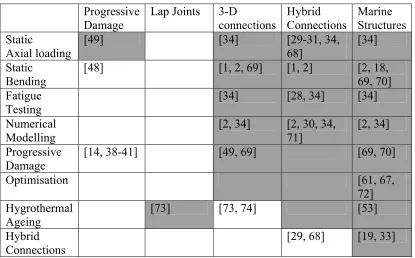
Table 2.1 Reference matrix 45 Table 3.1 Advantages and Disadvantages of Resin infusion over hand lay-up [75] 50
Table 3.2 Step by step resin infusion process 51
Table 4.1 Results of resin bulk tests 67 Table 4.2 DCB test specimen dimensions 68
Table 6.1 Fatigue life test matrix 88 Table 6.2 Results from the DLHC static tests 90
Table 6.3 Number of cycles to failure of DLHC for 10% to 60% of UTS 93
Table 6.4 Out-of-plane residual strength test results 95 Table 6.5 Events recorded during residual test 95 Table 6.6 Results of the static tests on aged DLHC specimens 97
Table 6.7 Results for 4-point bend tests of aged and unaged DLHC specimens 98 Table 6.8 Failure load and Young’s modulus of aged and unaged composite material 99 Table 6.9 Number of cycles to failure of DLHC for 10% to 60% of UTS, aged and unaged100
Table 7.1 Mesh Convergence results 108 Table 8.1 Example joint parameters 118 Table 8.2 Densities of materials used for weight calculation 123
Table 8.3 Baseline HSC joint dimensions and performance properties 124 Table 8.4 Limits and resolution of case study double lap joint variables 131
Table 8.5 Genetic algorithm parameters 132 Table 8.6 Limits and resolution of joint input variable 133
Figure 1.1 Advantages and disadvantages of Steel, GRP and hybrid construction 150
Figure 2.1 Over-laminated joint from Hildebrand and Heintinen [27] 150 Figure 3.1 Typical location for a hybrid joint on a naval vessel (courtesy of DCN) 151
Figure 3.2 Schematic representation of HSC specimen (mm) 151 Figure 3.3 Schematic representation of the DLHC specimen (mm) 151
Figure 3.4 Lay up steel for DLHC specimens (mm) 152 Figure 4.1 Schematic representation of FORTRESS testing rig 152
Figure 4.2 Control and span transducer differences for FORTRESS 153
Figure 4.3 Experimental test set up for DLHC specimen 153 Figure 4.4 Experimental test set up for HSC specimen 154 Figure 4.5 Schematic of test setup for bending tests of DLHC (mm) 154
Figure 4.6 Experimental test setup for HSC bending tests 155 Figure 4.7 Mould for producing resin castings from steel BS template 155
Figure 4.8 Typical stress-strain curve for resin casting in tension 156
Figure 5.1 Progressive damage methodology 157 Figure 5.2 Maximum shear and Von Mises criteria 158 Figure 5.3 Schematic of material degradation post initial failure 158
Figure 5.4 Genetic algorithm methodology 159 Figure 6.1a Numerical simulation of HSC with anti-bending guides straddling the
balsa/steel interface 160 Figure 6.1b Numerical simulation of HSC with anti-bending guides supporting only the
steel 160 Figure 6.2 Annotated picture of HSC specimen compressive failure 160
Figure 6.3 Matrix whitening due to skin buckling during compressive static test of HSC –
external face of joint (see figure 3.1) 161 Figure 6.4 Axially compressive static test results for HSC with and without anti-bending
guides 161 Figure 6.5 Change in HSC stiffness and energy dissipation for 17%-34% UCSnom 162
Figure 6.6 Change in HSC stiffness and energy dissipation for 34%-69% UCSnom 162
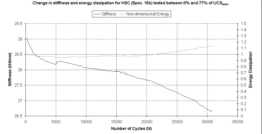
Figure 6.11 Change in HSC stiffness and energy dissipation for 0%-77% UCS , specimen 15b
nom
165 Figure 6.12 Change in HSC stiffness and energy dissipation for 0%-77% UCS , specimen
16a
nom
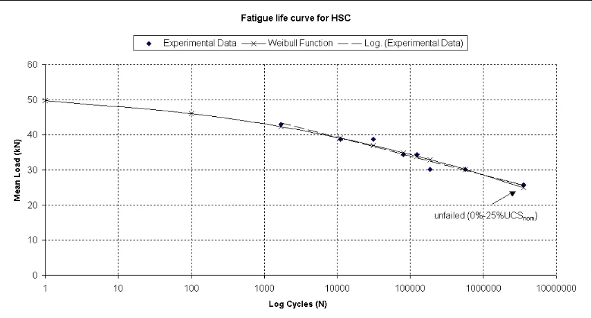
165 Figure 6.13 Fatigue life curve for HSC joint 166
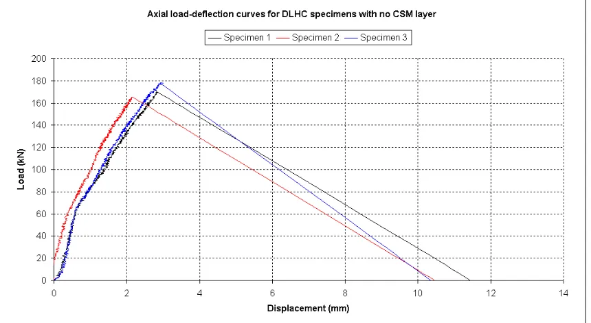
Figure 6.14 Static test results for DLHC with CSM interface 166 Figure 6.15 Static test results for DLHC without CSM interface 167 Figure 6.16 Comparison of load-deflection for the two DLHC lay-ups 167
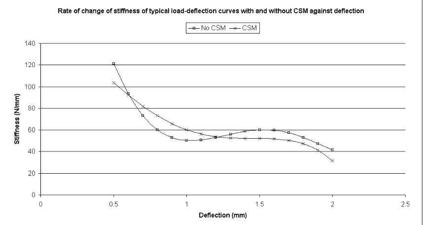
Figure 6.17 Comparison of stiffness against deflection 168 Figure 6.18 Pictorial comparison of failure surfaces with (a) and without (b) CSM layer 168
Figure 6.19 Load-deflection curves for 4-point bend of DLHC without CSM 169 Figure 6.20 load-deflection curves for 4-point bend of DLHC with CSM 169
Figure 6.21 Failure of DLHC in 4-point bend without CSM 170 Figure 6.22 failure of DLHC in 4-point bend with CSM 170 Figure 6.23 Comparison in stiffness change for DLHC in fatigue between 10% and 60% of
UTS 171 Figure 6.24 Fatigue failure surfaces of aged DLHC specimens 171
Figure 6.25 Change in HSC bending stiffness with increasing fatigue crack length 172 Figure 6.26 Load-displacement plot for out-of-plane residual strength test, 50mm fatigue
crack (see Table 6.4 for A-E information) 172 Figure 6.27 Failure of HSC joint in 4-point bending 173 Figure 6.28a Failure surface of tensile DLHC specimen, unaged 173
Figure 6.28b Failure surface of tensile DLHC specimen, aged 174 Figure 6.29 Comparison of tensile load-deflection response of unaged, aged 5544 hours and
aged 11592 hours 174 Figure 6.30 Percentage changes in failure load and failure displacement with increasing
hours of ageing 175 Figure 6.31 Load-deflection curves for DLHC specimens in 4-point bending unaged and
aged 18936 hours 175 Figure 6.32 Pictures of DLHC failures in 4-point bending with (18936 hrs) and without
Figure 7.4 Influence of initial displacement increment size on final resultant load 178 Figure 7.5 Finite element result compared to experimental result for HSC in compression 178
Figure 7.6 ANSYS model indicating the location of adhesive areas 1 and 2 179 Figure 7.7 Location of the maximum Von Mises stress in the adhesive layer
(
σ
VM≥50 MPa) 180Figure 7.8 Stress components in adhesive area 1 (Fig. 7.6) at steel/adhesive interface for
0.72 mm displacement 181 Figure 7.9 Adhesive elements with modified stiffness properties at location of maximum
Von Mises stress (MPa) 181 Figure 7.10 Stress components present at interface of steel and adhesive with modified
element properties 182 Figure 7.11 Von Mises stress in the GRP skins displacement where adhesive failure occurs
(MPa) 182 Figure 7.12 Comparison between the PDM and experimental load-deflection curves 183
Figure 7.13 Stress reduction models for the progressive damage model 183 Figure 7.14 Location of first failure in the progressive damage model 184
Figure 7.15 Progression of damage in the joint 185 Figure 8.1 Comparison of shear stress between FEA and Allman for a single lap joint 186
Figure 8.2 Comparison of peel stress between FEA and Allman for a single lap joint 186 Figure 8.3 Maximum shear, peel and Von Mises stress against adhesive thickness using
Allman’s theory 187 Figure 8.4 Shear stress distribution with variations in adhesive thickness using Allman’s
theory 187 Figure 8.5 Peel stress distribution with variations in adhesive thickness using Allman’s
theory 188 Figure 8.6 Maximum shear, peel and Von Mises stress against overlap length using
Allman’s theory 188 Figure 8.7 Shear stress distribution with variations in overlap length using Allman’s theory189
Figure 8.8 Peel stress distribution with variations in overlap length using Allman’s theory189 Figure 8.9 Maximum shear, peel and Von Mises stress with variations in Young’s modulus
Figure 8.11 Peel stress distribution with variations in Young’s modulus using Allman’s
theory 191 Figure 8.12 Percentage change from baseline of stress, stiffness and weight with changing
adhesive thickness from FEA 191 Figure 8.13 Peel stress distribution in adhesive layer with variations in adhesive thickness
from FEA 192 Figure 8.14 Shear stress distribution in adhesive layer with variations in adhesive thickness
from FEA 192 Figure 8.15 Percentage change from baseline of stress, stiffness and weight with changing
core thickness from FEA 193 Figure 8.16 Percentage change from baseline of stress, stiffness and weight with changing
skin thickness from FEA 193 Figure 8.17 Shear stress distribution in adhesive layer with variations in adhesive thickness
from FEA 194 Figure 8.18 Peel stress distribution in adhesive layer with variations in adhesive thickness
from FEA 194 Figure 8.19 Percentage change from baseline of stress, stiffness and weight with changing
GRP/steel bondline length from FEA 195 Figure 8.20 Comparison of the deformation of a short (a) and long (b) bond length from
FEA 195 Figure 8.21 Percentage change from baseline of stress, stiffness and weight with changing
taper length from FEA 196 Figure 8.22 Lateral deflection (exaggerated) of long (a) and short (b) taper lengths from
FEA 196 Figure 8.23 Shear stress distribution in adhesive layer with variations in taper length from
FEA 197 Figure 8.24 Percentage change from baseline of stress, stiffness and weight with bond
length to taper ratio from FEA 197 Figure 8.25 Shear stress distribution in adhesive layer with variations in bond length to
taper ratio from FEA 198 Figure 8.26 Peel stress distribution in adhesive layers with variations in bond length to taper
Figure 8.28 Comparison of changes to geometry on maximum Von Mises stress from FEA199
Figure 8.29 Comparison of changes to geometry on global stiffness from FEA 200 Figure 8.30 Comparison of changes to geometry on the weight of the joint from FEA 200
Figure 8.31 Schematic of double lap joint for optimisation test case 201 Figure 8.32 Influence of population size on GA performance 201 Figure 8.33 Influence of selection group size on GA performance 202 Figure 8.34 Influence of crossover probability on GA performance 202 Figure 8.35 Influence of mutation probability on GA performance 203 Figure 8.36 Progression of GA for repeated runs minimising weight 203 Figure 8.37 Percentage change in performance for parametric and GA results for minimum
weight 204 Figure 8.38 Progression of GA for repeated runs minimising Von Mises stress 204
Figure 8.39 Percentage change in performance for parametric and GA results for minimum
Von Mises stress 205 Figure 8.40 Percentage change in performance for parametric and GA results for maximum
CFRP Carbon Fibre Reinforced Plastic CSM Chopped Strand Mat
DCB Double Cantilever Beam DLHC Double Lap Hybrid Connection FEA Finite Element Analysis
FRP Fibre Reinforced Plastic GA Genetic Algorithm GRP Glass Reinforced Plastic HSC Hybrid Structural Connection MCMV Mine Counter Measure Vessel PDM Progressive Damage Model SRMH Single Role Mine Hunter
TSRL Transport Systems Research Laboratory VMC Von Mises Criterion
I would like to thank the following:
My supervisors, Prof. Ajit Shenoi and Dr. James Blake for their continual guidance and encouragement throughout the course of this research.
Dr Jagath Mawella for his sponsorship of the current research and his colleagues at the UK Ministry of Defence for advice and discussions.
My colleagues past and present for informal chats and discussions on the subject of composite materials and structures, Elouan Jarry, Gleb Makarov, Narasimhan Sampathkumar, Dan Holmes, Richard Trask and others who I may have forgotten.
Dr Mingy Tan and Dr. James Blake for the development of the genetic algorithm and multi-objective function modules for the optimisation routines
The technical staff in the School of Engineering Sciences that helped sort out various problems, Dave Beckett, Erik Roszkowiak, Bob Barnes and James Chitty.
James, Dominic, Janice and anyone else who joined me in the bar for a discussion on anything but work and putting the world to right!
The people at Southampton Hockey Club for giving me something to do outside of work to relieve the pressure of completing this research, whether it be hockey, golf, an occasional quiz night or meeting my future wife.
Chapter 1
Introduction
Steel has been the material of choice for the construction of large ships since the late 1800’s. From the 1940’s onwards welding began to replace riveting as the most common joining method. Steel is still extensively, if not exclusively, used for the construction of large transoceanic cargo carrying vessels such as oil carriers, bulk carriers and gas carriers and in the foreseeable future this is unlikely to change. The majority of naval vessels at present are constructed from steel however the use of more lightweight materials for the construction of naval platforms has been under investigation for a number of years. Aluminium became the material of most interest. However, due to its relatively low melting point and its loss of structural integrity at relatively low elevated temperatures, it is no longer used for structural applications in the Royal Navy.
increase in speed or payload capacity can be achieved, the former being important to the consumer in the pleasure craft industry, the latter for the commercial industry. In recent years the use of composite materials for vessels greater than 60 metres has extended the knowledge and experience in their application to alternative sectors of the marine market. For example, composite materials can now be found in the offshore oil industry and naval platforms. The Royal Navy Single Role Mine Hunters (SRMH) and the Mine Counter Measure Vessels (MCMV) are built entirely from glass reinforced polyester resin. These vessels up until recently were the largest composite vessels. The advantage of using composite materials in this application is to remove the threat of magnetic mines by having a non-metallic mine hunter. More recently, the Swedish Navy has introduced a fully composite corvette (Visby) constructed from carbon fibre reinforced epoxy sandwich and even more recently the largest composite vessel “Mirabella V” was launched, a 75m sailing yacht. For very large composite ships, longitudinal strength is an issue. This requires substantial FRP laminate thicknesses to create an efficient hull girder. Thick laminates have their own problems associated with the polymerisation of the resin being an exothermic reaction producing heat, which is exacerbated when in large volumes (i.e. thick sections).
At present, for ships over 100 m in length, steel is still the preferred material for main hull girder construction where longitudinal strength is the main design consideration. In order to take advantage of lightweight materials such as FRP composites, consideration must be given to their application in secondary structures i.e. superstructures. The construction of the superstructure block is relatively easy given the advances in FRP processing technology. The key difficulty is the connection between the FRP composite and the steel hull. Steel is joined traditionally by welding (i.e. hot work) while FRP to FRP joints in ships are usually adhesive bonds. Composite to steel connections can therefore be either bonded or bolted. Bolting is largely avoided in ships since it introduces problems of watertightness. Therefore bonded connections are the preferred option.
In recent times the design of new engineering structures, not solely in the marine industry, has focused on small refinements of design rather than huge technological leaps. One design refinement that is of particular interest to the marine industry is to assess the weight distribution of the structure. Structural engineers are beginning to investigate the feasibility of using a mixture of materials within a single structure to tailor the weight distribution for its particular application. In the marine industry, stability of the vessel is an important design aspect. This is especially true in naval applications, where the ship must be an efficient and stable platform from which to launch ordinance, aircraft or conduct other activities in a wide range of sea and manoeuvring conditions. In this application it is the weight distribution vertically that is of importance to the naval architect. By reducing weight aloft, the centre of gravity of the ship can be lowered and hence the roll and pitch stability characteristics of the ship can be improved. The use of a mixture of materials in the design of such naval platforms, incorporating lightweight materials, could provide significant advantages for the marine industry as a whole.
The aim of the present research is to examine the performance of hybrid connections and gain an understanding of how the load is transferred through the joint, how the stresses develop within the joint that induce failure, how failure occurs and progresses for present joint designs. Finally, based on this research of how current hybrid connections perform, a new generation of hybrid joints is proposed and their structural performance assessed. Previous studies investigating the use of hybrid connections have concentrated mainly on static strength [1-4]. The objectives of the current research are to:
• Identify the strength and durability characteristics of a hybrid structural connection (HSC), which is representative of a full-scale structural element;
• Identify the strength and fatigue characteristics of a small-scale double lap hybrid connection (DLHC) in an unaged condition and after artificial hygrothermal ageing to identify the effect if any of moisture ingress;
• Investigate possible changes to the joint design to improve the performance of the HSC through numerical studies.
finally looks at the use of numerical techniques for the identification of progressive damage in structures. Chapter 2 identifies the gaps in the present knowledge of hybrid connections and the analysis of adhesively bonded joint damage progression and addresses how the present research will provide information to future structural engineers and naval architect so that improvements can be made to the design of hybrid connections.
Chapter 3 introduces the joint design philosophy, materials and manufacturing methods for hybrid connections. The thought processes for the design of the HSC and the DLHC are described. Chapter 4 outlines the experimental facilities used for the present research. There is also a clear description of the tests that will be carried out and the methods used in the data analyses. The accelerated ageing process is also outlined in this chapter. The numerical methods used in the present research are outlined in Chapter 5. This chapter aims to describe the progressive damage method, beginning with the finite element analyses (FEA), through the failure criteria that are applied to the progressive damage model (PDM) and the property degradation post-initial failure. It is hoped that the combination of these three numerical methods can be brought together to help in the development of a tool to aid in the design of hybrid connections. In addition, this chapter outlines the methods used to investigate performance improvement of the HSC joint through parametric variations and formal optimisation routines.
The results from the experimental strength and durability characterisation of the hybrid joints are presented in Chapter 6 incorporating, static axial and bending strength, fatigue performance, residual strength and the influence of hygrothermal ageing. Chapter 7 investigates the numerical simulation of the joint with respect to performance under quasi-static loading and incorporates the methods outlined in Chapter 5.
Chapter 8 investigates the effects of geometric changes to the HSC by finite element analysis. The parametric changes to the joint will be assessed with respect to a base design. In addition an optimisation technique involving genetic algorithms is used to obtain the optimal solution with respect to weight, maximum stress and global stiffness. Chapter 9 draws conclusions on the work carried out under the present research.
Chapter 2
Background and literature review
2.1. INTRODUCTION
This chapter involves the examination of ship structures and their evolution which has lead to the desire to match traditional ship construction materials such as steel with more modern lightweight materials such as fibre reinforced plastic (FRP). The reasons for the application of hybrid structures to modern marine vessels are examined through the literature on the application of such structures.
The use of composite materials involves different production processes compared to traditional shipbuilding methods. Therefore the methods whereby the steel and GRP materials can be connected are an important factor in the success of hybrid structures. The methods used to connect dissimilar materials are wide and varied and the method in which the hybrid connection is manufactured will influence the performance of the joint when subjected to loads encountered onboard a marine vehicle.
2.2. EVOLUTION OF SHIP STRUCTURES
Ship structures have developed rapidly from the days when wood was the material used to construct large sailing ships for trade and naval applications. Iron and then its derivative steel, which has become the backbone of ship construction worldwide, superseded wooden construction [5]. Aluminium was introduced as a ship building material where ship operators were looking for faster and more efficient vessels. The high-speed ferry market where faster and faster crossings were required drove this construction materials usage. As the search for further gains in structural efficiency continued GRP or composite materials were the next material destined for use in marine structures
Composite materials made their first appearance in the marine industry soon after the Second World War in the construction of small personnel boats for the US navy. Pressure bags and vacuum injection were the manufacturing methods of choice at this time and were required to deal with the high pressure curing resins. With the development of low pressure, room temperature curing resins, hand lay-up became a popular manufacturing method and lead to a ‘boom’ in the use of GRP in boat construction. The success of composite materials in the small craft field can be attributed to a number of factors including [6]:
1. Competitive first cost: particularly where a number of hulls are to be built from the same design.
2. Lower labour skill level compared to the that required for traditional wooden hulls 3. Low maintenance finish to hull resulting from the seamless and leak-proof qualities
of GRP.
4. Low cost of repair
5. Ability to produce complex shapes for hydrodynamic or aesthetic purposes.
Between 1955 and the 1980’s the number of boats constructed from GRP had grown from 4 to 80 percent [7, 8]. A historical view on composite materials can be found in Appendix I.
2.2.1.1 Naval applications
absorption and poor construction quality it was the first real move away from wooden MCMV’s. Other applications during this time included: 9.5m patrol boats used on the rivers during the Vietnam war; Sonar domes, fairwaters, fins and non-pressure hull casings for submarines and masts, radomes, piping, crew shelters, hatch covers and deck houses for surface war ships.
The late 1960’s and early 1970’s saw both the US Navy and Royal Navy producing 100 percent glass reinforced plastic MCMV’s. The first being the HMS Wilton of the Royal Navy at 46.6m long and 450 tonnes full-load displacement. The success of HMS Wilton led to the rapid expansion of the use of composite materials for MCMV’s and since the 1980’s more than 200 all-composite MCMV’s have been built, many over 50m long and 600 tonnes full-load displacement. It should be emphasised that the design of these vessels was driven by the requirement for non-metallic hull-envelopes to avoid the detonation of magnetic mines. This requirement evolved due to a reduction in expertise in the construction of wooden vessels previously used for minhunting. However, specific expertise was developed in the construction of large vessels using GRP.
One major driver towards the use of composite materials for naval (and commercial) applications is the stiffness property advantages that it provides. In steel ships large stress concentrations can be found at the corners and connections between the superstructures and the deck [6]. This can result in fatigue cracking of the deck and surrounding areas. The use of composite materials in this application can provide relief from this phenomena due to the differences in stiffness between the steel and the GRP superstructure. The reduced stiffness of the GRP reduces the stresses transferred through the deck and connection during global hull-bending. This reduces stress concentration and hence reduces the possibility of fatigue cracking of the deck.
2.2.1.2 Commercial applications
2.2.1.3 Recreational applications
Probably the most active area for composite construction is in marine pleasure craft. Mass production of small, medium and relatively large sailing and motor yachts in GRP have lead to a reduction in material cost. In addition to material costs, development in construction techniques and material types has led to a reduction in labour input and turnover for each hull.
The high performance racing yacht industry is often where major development of the use of composite materials, for example composite masts were once only used in high performance racing yachts. However, in recent years the technology has matured and the confidence in their performance has allowed their application to production blue water cruisers. Yachts in the racing field usually have high material and fabrication costs as speciality material combinations and fabrication methods are employed. Combinations of carbon, aramid and glass reinforcement can often be found, bound in relatively expensive epoxy resin systems. The designs of these yachts commonly take risks beyond what is acceptable in the other marine fields. Durability is sometimes sacrificed for minimum weight in an effort to outperform the competition. Incidents such as the structural collapse and sinking of Australia’s entry (AUS 35) to the 1995 America’s Cup after only 21 races [10] prove that racing yachts are built to the limit of the materials in an effort to gain fractions of a knot of boat speed. This type of construction stretches the technological limits and both failure and success provide valuable spin-off technologies in design methodology and material limitations that can be applied to lower-performance composite application.
make this uneconomical. In addition there is also limited expertise in the construction of very large vessels in terms of the present manufacturing and design technology. However, the benefits that composite materials bring to an engineering structure make it an excellent candidate for construction. Understanding the design and fabrication of structural connections for the application of composite materials to weight critical areas of a vessel is vital.
In the 1980’s and 1990’s a number of studies were conducted on the performance of steel/composite ship superstructures under nuclear air blast conditions [11, 12]. The hybrid deckhouse consisted of GRP panels bolted to a steel internal frame system. The results suggest that under moderate blast loadings the hybrid structure will experience smaller displacements due to the rigidity of the steel frames. However, under extreme blast conditions the GRP structure is destroyed but the hybrid structure remains intact. The GRP structure is destroyed due to the excessive strains in the GRP stiffeners. However, the hybrid structure is able to plastically deform due to the ductile nature of the steel framing. Although this is an early application of composites to the production of superstructures, the work conducted does not deal with the connection of the GRP superstructure to the deck. In addition, Chalmers [13] discusses in detail the use of composite materials in marine vehicles. One application being the superstructure, again however, the subject of the connection between the steel and FRP is highlighted as an area for future research to ensure that it is durable in the marine environment and capable of withstanding fire.
2.3. STRUCTURAL CONNECTIONS
• Fretting of the composite materials, particularly under cyclic loading
• Fibre discontinuity caused by the drilling of holes in the laminate
• Possible micro-cracking of the laminate during the drilling process
The second process used for the jointing of composite materials, and the process which is discussed throughout the presented research, involves the adhesive bonding of the components.
In recent years the application of adhesives as a structural jointing mechanism has become more accepted within engineering design. Adhesives are being applied in industries that include aerospace, marine and automotive. Most engineering structures consist of a number of component pieces that are connected to provide a load path between components. Joints can be assembled in a variety of ways including bolting, riveting, welding or adhesive bonding. Bolted or riveted joints can only achieve a maximum tensile strength of 50 percent of the weakest adherend due to the stress concentrations located at the holes. However, adhesively bonded joints can achieve in excess of 80 percent of the tensile strength of the weakest adherend using just a simple shear joint configuration [16].
It could be said that the weakest part of any structure will be its joints, regardless of whether a mechanical fastening or adhesive bond is used. Furthermore, a weight penalty may be incurred, as the joints may require additional material to compensate for a reduction in stiffness or strength in the region of the joint.
Compared to other techniques adhesive bonding can provide economic and performance advantages [17] to the structural engineer including;
• The ability to join dissimilar materials, especially in harsh environments where, for example, dissimilar metals may cause galvanic corrosion if in direct contact. The use of adhesives provides an insulating layer between these materials;
• The ability to join thin sheet material efficiently and without distortion;
• Reduced cost due to relatively unskilled labour input. The adhesive dispensing process can be fully automated insuring repeatability;
• Flexibility of design allows novel joint concepts to be used with a wider range of materials.
However, as with any engineering process there are some disadvantages [17] including;
• Time involved in achieving 100 percent joint strength, especially if cold cure adhesives are used;
• Long term extreme load durability is relatively undocumented;
• Designing of the jointed area is intensive and may require optimisation for each load condition;
• There is a limit to the upper service temperature of adhesives and this is dependant on the adhesive used;
• Non-destructive evaluation of joints is limited in comparison to alternative mechanical jointing techniques.
• Poor performance under dynamic loading such as blast
There are a large number of studies in the literature which discuss the use of adhesive joints for applications where the bond is made between similar and dissimilar materials. The advantages discussed above refer to the non-distortive nature of adhesive joints. This is particularly advantageous when bonding thin metallic sheets such as those found in the aerospace industry. Welding of such thin plates can lead to substantial distortions which may require remedial work, which is both time consuming and labour intensive. The application of adhesive bonding of thin plates removes the distortions due to heat and hence expensive remedial work [18].
joint but also the insulation between the two materials, which when in contact can result in an electrolytic reaction causing corrosion of one or both metals.
One of the most obvious applications of adhesive bonding is in the connection between non-metallic, non-weldable materials, such as FRP. There has been extensive research into the design of adhesive joints for use in the composite industry [20-25].
2.3.1 HYBRID CONNECTIONS
Metal-to-composite joints are most readily found in the aerospace industry for the attachment of lightweight composite components to metallic sub-structures. Initially, the use of the metal-to-composite joint was restricted to composite repair patches for metallic structures.
A number of research programmes have investigated the use of such patches in terms of fatigue life and compared them to traditional riveted/bolted aluminium patches. Ong and Shen [26] investigated the patch repair of aluminium honeycomb panels using carbon and boron reinforced patches. The aim of the work was to demonstrate that the use of a composite patch would provide superior fatigue characteristics than a more standard riveted aluminium patch. It was found that the fatigue life was increased three fold. Tay et al. [27], also investigated the use of boron reinforced patches for cracks near holes in aluminium structures. This research also found an increased fatigue life and reduced rate of crack growth using composite patches rather than more traditional aluminium patches. Naboulsi and Mall [28] characterised crack growth rate in aluminium panels with bonded composite patches. And developed a numerical tool for either predicting the fatigue life of a composite patch, or alternatively, for designing a patch repair for extended fatigue life. The use of metal-to-composite connections began expanding into other industrial sectors and as the use of composites as a structural material became more accepted, increased applications were being found.
mechanical performance compared to current steel parts. In addition to the mechanical performance, it was found that the use of composites reduced part weight. However, a number of issues were highlighted for further work prior to full acceptance of such component parts, including performance during and after environmental exposure and long-term performance.
The use of joints between metals and composites has expanded to provide substantial proportions of some structures to be made from composite materials. One reason for this move is an effort to reduce overall weight. One such application is the manufacture of composite outer shell structures for train carriages. Shin et al. [30] investigated adhesively bonded lap-joints for composite-steel shell structures for high-speed trains. The use of composites in such applications aids the demand for increased speeds. This research investigated the joint between the upper composite car body and the steel chassis. The joints used were lap joints of both single and double configuration. The joints were loaded to represent an internal pressure force within the carriage. This simulated the train passing through a tunnel at high-speed. It was found that a single-lap joint with the composite as the inner lap produced the best results. However, this research investigated only the joint strength in terms of a pressure vessel and did not include global bending or twisting of the carriage.
The use of metal-to-composite joints has extended into the marine field as a novel method of incorporating lightweight GRP superstructures to steel hulls. The advantages of using such technology are most apparent in naval vessels. Warships are required to function in a wide variety of sea states. Even in the worst sea states they are expected to operate effectively as platforms for numerous instruments and weapons. For this reason seakeeping is an important aspect in the design of a warship hull. One way of improving seakeeping ability is to reduce the vessel’s centre of gravity without increasing vessel weight. Structures such as masts, superstructures and even internal non-strength decks and bulkheads can contribute to weight aloft. Replacement of such structures using composite materials could provide substantial savings in weight and increase seakeeping ability and vessel stability.
Hildebrand and Hentinen [32] investigated solutions to joints between large FRP-sandwich and metal structures. Four joints are considered in this work, but the most relevant with respect to the presented research and most thoroughly discussed is the over-laminated joint (Figure 2.1). This consists of an aluminium or steel section that is laminated into an FRP-sandwich panel. Experimental static compression and bending tests were carried out in addition to numerical analyses. The static strength was found to be adequate compared to the strength of the sandwich panel. All four joint concepts were deemed to be feasible. The composite panels, with associated metallic inserts, would be welded to the steel deck. Problems associated with heating during the welding process could be avoided by locating the adhesive bond a reasonable distance from the weld. The comparison of a bolted joint with the overlaminated joint highlighted the bonded joint as being superior in terms of static strength but also in terms of cost during joining by as much as 50%.
superstructure assemblies had been built and a third was under construction. It was found that the manufacturing of the composite structure was more expensive than a metal alternative, but in terms of through life cost and the technological advantage, the composite superstructure was more beneficial than metal.
Wright et al. [34] investigated FRP-steel connections for structural transverse bulkheads in ship structures. In contrast to the joint configuration used by Le Lan et al. [33] the joint configuration in this work bonded the steel to the laminate and is described as an optimised ‘tuning fork’ connection. The 83m VT-designed corvette was used to examine the feasibility of using large FRP sandwich panels as major bulkheads. Three bulkheads were chosen for the investigation, a collision bulkhead and two bulkheads bounding the machinery space near amidships. The composite bulkheads were designed to satisfy the same criteria as their metallic counterparts. Finite element analysis was used to assess the composite bulkhead performance and it was found that 8 mm skins on a 50 mm balsawood core would satisfy the design criteria. Static and fatigue tests were carried out on the ‘tuning fork’ joint and it was found that satisfactory connections could be designed to ensure structural integrity. Numerical strength predictions were in good agreement with the experimental results and indicated that relatively simple maximum shear stress failure criteria can be used for strength prediction of the joint.
Clifford et al. [2] also investigated a steel-to-composite joint for structural connections between a steel hull and a composite superstructure. The geometry of the specimens were similar to that of Le Lan et al. [33] and were tested as cantilever beams with a point load applied to the composite end of the joint. Two approaches were taken to improve the design of the original joint by altering the termination position of the steel and by changing the material used at the steel/sandwich core interface. Extensive numerical modelling was carried out using a fracture mechanics approach. Experimental values of interfacial fracture toughness were obtained from four-point bend delamination tests. The base design exhibited a sudden loss in stiffness under flexural loading. However, the relatively simple modifications provided a significant increase in performance. The properties of the steel/FRP interface were found to be critical in the performance of co-cured joints.
fully recognised. Two such areas of research that should be addressed before complete acceptance to full-scale manufacture are:
• fatigue life characterisation,
• durability of steel/GRP bond after environmental ageing.
These two topics are essential in deciding the suitability of hybrid connections for application in the marine environment.
2.4. SHORT-TERM LIMIT STATE – DAMAGE
The analysis of adhesive joints has been on going for a large number of years and has become a highly complex task with the advent of orthotropic adherend materials and developments in adhesive technology. In general the most studied joint is the single lap joint. The main reasons for this are its simplicity and it being the basis for many joint designs employed in practise. Perhaps the most obvious place to begin is with closed-form solutions developed to analyse adhesive joint stresses and stress concentrations in single lap joints.
Volkerson [35] was the first person to study the stresses arising from the differential straining of the adherends in the bonded single lap joint. This must be accounted for as the adhesive is not subjected to a uniform shear strain, as would occur if the adherends were rigid and were not subjected to strain themselves. Volkerson’s analysis assumes that the adhesive deforms in shear while the adherend only deforms in tension. However, two important factors are excluded from this analysis. In a single lap joint the applied forces will not be co-linear if applied to the central axis of the adherends. This subjects the joint to a bending moment in addition to the axial force. In addition, the bending moment will cause the joint to rotate due to the axial force. This leads to a geometrically non-linear problem.
adherend the bending moment factor is equal to one and as the joint bends under axial load it tends towards zero. However, it rarely goes below approximately 0.35. Goland and Reissner [36] considered two cases, firstly where the adhesive layer is thin and is of similar elastic properties to the adherends and secondly where the elastic properties of the adhesive are considerably different than the adherend. In the first case it was found that the tensile (tearing) stress, σyy, is very high at the edge of the joint and all stresses decrease with
increasing bending (decreasing k). In the second case it was found the tensile (tearing) stress is present however the shear stress concentration is twice as high as that obtained from Volkerson’s analysis [35].
These classical works were limited due to the peel and shear stress being assumed constant through the thickness of the adhesive. In addition the shear stress was assumed to be at a maximum at the end of the adhesive overlap. However, due to the end face of the adhesive being a free surface there can be no shear stress on it and thus, the law of complementary shears states that the shear stress at the joint end must be zero.
Allman [37] presented a solution which resulted in the correct zero shear stress at the ends of the adhesive joint, and a formulation for the peel stress distribution along the adhesive overlap. The Allman solution uses the Golland and Reissner [36] term, k, for the rotation of the joint due to eccentric loading. For flexible adherends or high applied loads this term approaches a value of 0.26, conversely for stiff adherends or low applied loads the value of
k approaches 1.0. For typical single lap joints with isotropic materials a value for k of 0.35 is suitable.
The majority of analyses consider the adhesives and the adherend behaving elastically. However, most modern adhesives usually exhibit an elastic-plastic behaviour. Hart-Smith [17] used closed-form solutions, incorporating iterative solutions for more complicated joints. It was shown that the inclusion of the plastic behaviour of the adhesives when loaded in shear reduced the shear stress concentrations substantially, however the tensile (tearing) stress, σyy, was still significant. Hart-Smiths [17] work concentrated on GRP and
The above analyses concentrate on closed-form solutions. However, with the advent of more affordable computing power, the use of more complex analysis tools have become more dominant in this field. Finite Element Analysis (FEA) is now the tool of choice for the analysis not just of adhesive joints but of any structure subjected to loading, whether thermal or structural. The extent of literature regarding the FEA of adhesive joints and composite materials is vast and will not be covered here. However, the current research does use specific FEA tools which will be reviewed later in this chapter.
A large number of studies into the progressive damage modelling of composites can be found in the literature. The majority of these are associated with in-plane loading of composite laminates with particular interest in defects such as notches and holes.
One possible reason for the large number of studies into damage progression modelling of composite laminates containing holes is the use of mechanical fastenings. Mechanical fastening of composite materials is commonly undertaken as a ‘belt and braces’ approach to the connection of components. The addition of a bolt or other similar fastening can serve as a redundant means to prevent structural collapse. However, it is well known that a hole in metallic structures results in stress concentrations around the hole. This is exaggerated in composite materials as holes result in fibre discontinuity and it is the fibres which carry the majority of the load. Due to fibre discontinuity at the hole, the load is transferred from the discontinuous fibres to the continuous fibres adjacent to the holes. This results in further stressing of the surrounding composite material. There are a large number of experimental studies looking at the effect of stacking sequence, geometric properties and lateral clamping pressure across the mechanically fastened joint between composite components [38-41]. Camanho and Matthews [14] describe a large number of investigations into predicting damage propagation prior to laminate failure in mechanically fastened joints in FRP. Some of these are described here.
Chang and Lessard [42] investigated laminated composite plates containing holes subjected to only in-plane compressive loads. As this study was only interested in the in-plane compression failure of the laminate, geometric buckling or out of plane deformations were not considered. This assumption allows the reduction of the problem to that of two-dimensional plane stress. Four failure modes are used in this study:
2. matrix compression, 3. fibre-matrix shearing, 4. fibre Buckling.
However, these failure modes were developed for use with unidirectionaly reinforced composites. Chang and Lessard [42] extended the failure criteria used by Chang and Chang [43] to include the fibre buckling and fibre-matrix shearing failures. The failure criteria used by Chang and Chang [43] was based on the work by Hashin [44]. No out-of-plane failure criteria, i.e. delamination failure, were included in this analysis. The effects of ply orientation, ply clustering and geometry on the strength and response of laminated composite plates containing a hole were also studied. Good agreement between the numerical and experimental work was observed.
Dano et al. [15] investigated the effect of including all the essential mechanical aspects of mechanically fastened joints, namely a full contact finite element model that includes friction and bolt clearance, non-linear shear behaviour, large deformation theory and property degradation. The paper concentrates on the influence of failure criteria and the inclusion of both geometric and shear non-linearities.
Gamble et al. [45] investigated the growth of damage in carbon fibre composite materials. The method involved constructing a finite element model of the specimen or component. The material properties for each ply and any known defects were defined. The load was added incrementally and stresses and strains calculated. The model was examined for areas of damage and if found suitable material property degradation was applied. Two damage criteria are discussed in this study, stress-based and strain-based. The stress-based criterion used was a modified Hill criterion [46].
any damaged layer in the system is replaced with a degraded homogeneous layer. Maximum stress and Tsai-Wu failure criteria are used. Degradation factors are used to alter the stiffness of the elements once failure has occurred. A parametric study on the effects of various degradation factors was carried out and provides guidelines for their appropriate selection. Good correlation between experiment and predicted results was found for two distinct beams, a graphite/epoxy and a glulam reinforced with GRP.
Padhi et al. [48] investigated the ultimate collapse of laminated composite panels under transverse loading. A number of commonly used failure criteria such as Tsai-Wu and Tsai-Hill are used to predict failure mechanisms. The analysis is non-linear in that the material properties are degraded with the onset of damage and the model is geometrically non-linear to account for the large deformations present with such a loading regime. It was found that the predictions correlated well with experimental data for panels of differing aspect ratios.
Feih et al. [50] use FEA analysis, appropriate failure criteria and material property degradation models to investigate the damage evolution of CFRP peel joints. This work uses the Hashin failure criteria for the composite material. For the adhesive, failure is assumed to occur when the maximum tensile strain is reached. In the experiment, initial failure occurs in the adhesive fillet propagating into the first ply. Numerically however, the initial failure occurs in the first ply with failure occurring in the adhesive fillet at a larger displacement. This may occur due to an underestimate of the adhesive failure criteria. As was mentioned, only the maximum tensile strain is considered. This is essentially a non-interactive failure criterion. By employing an non-interactive criterion, failure could be predicted in the position observed in experiment due to the combination of tensile and shear strains.
Feih et al. [51] examine the effects of different material degradation models on the progressive failure of an isotropic plate with a drilled hole. The degradation applied was to reduce the Young’s modulus by 20 percent after Von Mises yielding criteria. Four methods of applying the degradation were studied:
Method 1: Stabilised integration point degradation Method 2: Stabilised homogeneous element degradation Method 3: One-by-one integration point degradation Method 4: One-by-one homogenous element degradation
Method 1 is the simplest of the 4 methods. The material properties are degraded locally at the integration points. This method does have a problem with regard to 'healing’ effects. This effect occurs if the integration point information is stored in an array that is only updated after each load increment. Within each load increment there may be a number of equilibrium iterations. Convergence of the equilibrium iterations relies on the failed integration points remaining failed until equilibrium is reached. This phenomena is seen as a ‘jumping’ effect where integration points exhibit alternating failure within an element in subsequent iterations. Storing the current integration point states for each equilibrium iteration and using this to update the increment integration point array once convergence has been achieved can avoid the ‘jumping’ or ‘healing’ effect.
point values indicates failure. However, a current element damage array is required to prevent healing of previously failed elements.
By using either method 1 or 2 the result shows a degree of increment-size dependency. If the number of increments used to solve the problem is changed the prediction of damage may also differ. It was found that this effect had a greater impact when high mesh densities were used. It was found that by minimising the failure to one element per iteration of every load increment a more stable failure path is achieved. However, this can only be applied to the first iteration of each load step as this criteria requires knowledge of the iteration number. This may lead to more than one element failure occurring in iterations subsequent to the first.
Methods 3 and 4 avoid this problem by only allowing one integration point/element to fail per iteration. The failure values for the model are stored in an array and only the integration point/element with the largest value is deemed to have failed. Increment reduction is therefore no longer necessary, as these methods are completely stable.
2.5. LONG TERM PERFORMANCE – FATIGUE AND AGEING
The ageing of composite materials is an area of research that is generating a growing interest. Due to the performance advantages of FRP they are gaining wider use in both commercial and military applications. As the technology behind composite construction and processing increases and application becomes more wide spread, the material performance challenges increase correspondingly. One such challenge is the performance of composite materials after exposure to high temperature and moisture content environments, the marine industry being one such environment. For a small craft the water temperature can range from extremes of cold to relatively warm dependant on global location. In addition, saltwater spray, ballast tanks, wastewater tanks and bilge water on larger craft can all contribute to the environmental ageing process.
Ageing of composite materials can be said to occur in two forms;
hydrolysis of the resin, internal stress induced by water absorption causing fibre/matrix bond rupture.
2. Physical: This is a reversible process; by heating the material above its glass transition temperature the thermodynamic equilibrium is restored. The water molecules are removed from the resin matrix by this process.
In general the absorption of water into the matrix material causes the material to swell. This increases the distance between the chains of polymeric molecules, reducing the bonding forces within the structure resulting in a softer more ductile polymer matrix [52].
Moisture can be absorbed into a polymeric material via a number of channels either along the polymer chains or between the polymer chains [53]. The former method results in a more rapid ingress of moisture as less energy is required for the water molecules to penetrate the material. An analytical model can in most cases, describe the rate at which moisture is absorbed by a polymer. The rate of absorption is initially high; there is a slowing of the absorption rate as the saturation point is reached.
The application of the standard equations to moisture diffusion is clearly defined by Shen and Springer [54] where the expressions for the moisture distribution and moisture content as a function of time in both one dimensional homogeneous and composite materials exposed to humid air or water are presented. Test procedures are described for determining experimental values of moisture content and the diffusivity of composite materials. The experimental data is used to validate the numerical predictions of moisture content and distribution.
Springer [56] provides a comprehensive review of the literature regarding the effects on the performance of epoxy matrix composite materials. The study includes subjects such as absorption and desorption characteristics of single and multi-layered composite materials under steady and transient ambients. In addition, the author also looked at literature relating to the changes on mechanical performance. It was found, for example, that moisture content had a negligible effect on the tensile strength of laminates of 0-degree or 45-degree plies, however, there was a considerable loss (between 60-90 percent) of tensile strength in 90-degree laminates. A similar trend is true of elastic modulus of the laminates examined. One likely explanation is the tensile strength of the 90-degree laminates is dependent on the performance of the resin whereas the 45 and 0-degree laminates are more fibre dependent. Since the study in Ref. [56], further knowledge has been gained on the effect of moisture on the resin properties and would explain the considerable loss in mechanical properties of the 90-degree laminates.
Literature post-1979 extends the knowledge of the effects of moisture in a number of subject areas including material properties, the influence of new resin/fibre systems, modelling of moisture diffusion and detection of moisture.
Vauthier et al. [57] investigated the effect of hygrothermal ageing on glass-epoxy composite on fatigue performance. Two means of assessment were chosen, firstly by physio-chemical changes induced by water absorption and secondly, a mechanical approach coupling the effects between environment and fatigue. Damage mapping was carried out microscopically to relate the changes in fatigue properties to the distribution of fibre strength after ageing. The specimens were immersed in distilled water at 60°C for approximately 1 year.
It was found that the hygrothermal ageing substantially reduced the endurance properties of the composite during fatigue loading. This was related to a decrease in fibre strength. It was found that the increased pH levels especially at the matrix/fibre interface probably caused the decrease in endurance. It was implied that the pH increase might be due to the leaching of the unreacted curing agent remaining within the composite.
2.5.1 AGEING IN BONDED STRUCTURES
Although the diffusion in composites is an integral part of the current research the experimental specimens developed consist of an adhesively bonded joint. The process of diffusion into bonded structures can be said to be more complex than with bulk materials as there are an increased number of locations for moisture absorption. In a joint between two steel substrates, for example, there are two possible routes for moisture ingress – firstly through the adhesive material itself and secondly through the interface between the adhesive and the substrate. By introducing a semi-permeable substrate, such as composite material, a third ingress path through the substrate must be considered.
2.5.2 ACCELERATED AGEING
Criscioli et al. [58] investigated ways of further reducing the ageing process for composite materials. The method involves exposing the specimen to 100 percent humidity for a period of time, tc. After this time the humidity is reduced to a value corresponding to the required
moisture concentration and is achieved at time, tt. The problem lies in the selection of the
change-over time tc and must be chosen so that the moisture concentration is correct at
every point within the structure and the desired moisture concentration is obtained in the shortest possible time, tt. Equations for the calculation of tc are derived. Solution of the
equations is carried out using specialised software however the equations are summarised using dimensionless parameters. A sample problem was analysed and a value of change over temperature tc was found. The results were verified with experimental coupons. In
addition, the coupons were also subjected to normal ageing conditions. The mechanical properties of the coupons using both ageing processes were compared and it was found that both processes produced similar properties. This sample problem showed that the new ageing method produced aged specimens in a considerably shorter time (approximately 21 percent faster).
2.6. DESIGN OPTIMISATION
With the development of new materials, such as FRP, for the construction of ship structures, the requirement for structural connections for the construction of large vessels regardless of the material being used and the emphasis on short term and long term behaviour characterisation of structures for use in the marine industry has placed a high level of importance on efficient design. In the context of the present research efficient design is defined as the most efficient solution to meet the design requirements, for example low resistance for hull-form design or maximum pay load capacity for a given displacement. The present research concentrates on detailed design rather than global design issues. However, the methods of optimisation for both global and detailed design problems are the same.
case more complex optimisation techniques such as evolutionary algorithms can be applied. This method of optimisation is based on the traditional Darwinian theory of “survival of the fittest” found in nature. Competition in nature for finite resources results in the fittest individuals dominating over the weaker ones.
Genetic algorithms (GAs) form one of the evolutionary optimisation techniques and is inspired by natural selection and genetics. The method is very general and is capable of being applied to a wide variety of problems. However, its use in the optimisation of engineering problems is not as widespread as one may expect. The use of genetic algorithms began in the 1960’s by John Holland on the subject of cellular automation. This is a discrete model studied in mathematics and theoretical biology and consists of an infinite, regular grid of cells (similar to a page of graph paper). A typical example is that each cell can have two possible states, black and white, and has 8 neighbours (those cells touching it) therefore there are 512 possible patterns for the cell and its neighbours. The most common reference to cellular automaton is the “game of life” invented by John Horton Conway. Games such as this form the building blocks for what is now called genetic algorithms. Fogel [60] describes simulated evolutionary optimisation in terms of genetic algorithms, evolution strategies and evolutionary programming and provides a detailed review of simulated evolutionary techniques and identifies that it will form an important method of solution to real world problems but its advancement will come from “careful observation and abstraction of the natural process of evolution”.
Four main steps can be used to define evolutionary optimisation methods: 1. A number or population of guesses of the solution to the problem; 2. A way of judging the quality of each individual in the population;
3. A method of mixing the fragments of the better solutions to form a new population; 4. A mutation operator to ensure diversity of the population.
are relatively few examples in the literature of the use of GAs to solve particular design problems.
Day and Doctors [61], used evolutionary algorithms to assess the hydrodynamic performance of ship hull forms. The hull forms are described by a fixed number of variables based on mathematical curves. The variables are given a number of limitations to ensure realistic hull forms are created. The variables are then chosen at random to generate an initial population. Hydrodynamic resistance prediction based on the Michell integral [62] was used to assess each individual of the population. Selection was based on minimum resistance and “breeding” was carried out using crossover and mutations to create the new generation. The work showed that the use of GAs provided a robust and rapid first principles technique to assess the design space for minimum resistance hull forms.
Genetic algorithms were used along with a gradient method which used a truncated Newton algorithm [63] and a direct search approach to investigate two problems, a two-dimensional diffuser and a drag minimisation problem of a fixed area body in flow which can be defined by two and four variables respectively [64]. For the diffuser the goal was to maximise the static pressure recovery coefficient and for the drag minimisation the goal was minimum drag coefficient. In both tests it was found that the more traditional direct approaches of Newton and the direct search produced results in fewer evaluations than with GAs. However, it is agreed by the authors that the GA would be more suited to a large problem that contained a number of local optima in the design space. Neither of the problems examined in this work contained local optima. This is highlighted by the better optimum solution found in the higher dimensional problem of drag minimisation by the GA.
![Table 3.1 Advantages and Disadvantages of Resin infusion over hand lay-up [75]](https://thumb-us.123doks.com/thumbv2/123dok_us/8499304.347041/52.595.103.542.395.601/table-advantages-disadvantages-resin-infusion-hand-lay.webp)