Ames Laboratory Technical Reports
Ames Laboratory
11-1964
Au Fe vs Cu thermocouples
D. K. Finnemore
Iowa State University, [email protected]
J. E. Ostenson
Iowa State University
T. F. Stromberg
Iowa State UniversityFollow this and additional works at:
http://lib.dr.iastate.edu/ameslab_isreports
Part of the
Physics Commons
This Report is brought to you for free and open access by the Ames Laboratory at Iowa State University Digital Repository. It has been accepted for inclusion in Ames Laboratory Technical Reports by an authorized administrator of Iowa State University Digital Repository. For more information, please [email protected].
Recommended Citation
Finnemore, D. K.; Ostenson, J. E.; and Stromberg, T. F., "Au Fe vs Cu thermocouples" (1964).Ames Laboratory Technical Reports. 82.
Au Fe vs Cu thermocouples
Abstract
A calibration of gold iron thermocouples is given.
Disciplines Physics
IS-1046
IOWA STATE UNIVERSITY
Au Fe vs Cu THERMOCOUPLES
by
D. K. Finnemore, J. E. Ostenson and T. F. Stromberg
RESEARCH AND
DEVELOPMENT
REPORT
U.S.A.E.C.
~
IS-1046
Physics (UC-34)
TID 4500, October 1, 1964
UNITED STATES ATOMIC ENERGY COMMISSION
Research and Development Report
Au Fe vs Cu THERMOCOUPLES
by
D. K. Finnemore, J. E. Ostenson and T. F. Stromberg
November, 1964
Ames Laboratory at
Iowa State University of Science and Technology F. H. Spedding. Director
2 IS-1046
This report is distributed according to the category Physics (UC-34) as listed in TID 4500, October 1, 1964.
r - - - -
LEGAL NOTICE---
---.
This report was prepared as an account of Government sponsored work.
Neither the United States, nor the Commission, nor any person acting on behalf of the Commission:
A. Makes any warranty or representation, expressed or implied,
with respect to the accuracy, completeness, or usefulness of
the information contained in this report, or that the use of any
information, apparatus, method, or process disclosed in this report may not infringe privately owned rights; or
B. Assumes any liabilities with respect to the use of, or for damages resulting from the use of any information, apparatus, method, or process disclosed in this report.
As used in the above, "person acting on behalf of the Commission" includes any employee or contractor of the Commission, or employee of such contractor, to the extent that such employee or contractor of the Commission, or employee of such contractor prepares, disseminates,
or provides access to, any information pursuant to his employment or
contract with the Commission, or his employment with such contractor.
Printed in USA. Price
$
l. 00 Available from theIS-1046 3
Au Fe vs Cu THERMOCOUPLES
D. K. Finnemore~ J, E. Ostenson and T. F. Stromberg
ABSTRACT
A calibration of gold iron thermocouples is given.
1
Berman and Huntley have shown that Au doped with a few
hundredths of a percent Fe makes a satisfactory thermocouple element
at low temperatures. They find that a gold+ 0. 03 at.
o/o
iron~ silvernormal thermocouple is reproducible to better than 0. 5% and has a
sensitivity greater than 10 ~V /°K in the temperature range from 1 to
20°K. We have measured the thermoelectric voltage of Au 0. 07 at. %
1
Fe vs Cu and find results complementary to those of Berman.
):c
The Au-Fe wire, prepared by Engelhard Industries, Inc.. is
drawn into 0. 006 in. diam wire, annealed at 550°C for 12 h in a reducing
atmosphere and then insulated with heavy formvar. For the second
wire of the thermocouple we have chosen copper because high purity
wires are readily available. For applications where thermal
conduc-tivity must be low, silver normal would be a more appropriate second
element. The voltages are measured with a Leeds and Northrup type
K-3 potentiometer and a 0. 0006 JJA/mm Leeds and Northrup galvanometer.
'
4
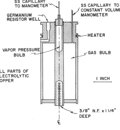
Temperatures in the range from 4. 2 to 20°K are determined by the
constant volume gas thermometer shown in Fig. 1. The entire 135 cc
gas bulb is machined from high purity copper. Eight deeply recessed
holes are cut in the top block to accommodate either germanium
resistors or Au-Fe thermocouples. The copper rod which runs down
the center of the bulb contains both the 2 cc vapor pressure bulb and a
threaded hole for affixing other experiments. A special groove is cut
in the main block for an astatically wound manganin heater. Another
groove just above the heater provides an area for thermally connecting
the electrical leads to the copper block before they go to the resistors
or thermocouples. A shield which surrounds the gas bulb provides a
thermal reservoir at a temperature approximately 0. l°K below the gas
bulb temperature. All connections to the gas bulb are thermally
connected to this shield. The vapor pressure line is a 0. 052 in. i. d.
stainless steel capillary; the gas bulb line is a 0. 020 in. i. d. stainless
steel capillary. A copper -constantan thermocouple is cemented to the
gas bulb capillary at approximately 30o-K to assist in the calculation of
the dead volume correction. With the assumption that the thermal
conductivity of the capillary varies linearly with temperature, we
calculate the maximum dead volume correction to be one part in 900.
The filling pressure of 3 Torr/°K gives a maximum non-ideality 2
cor-rection of 0. Ol6°K. Thermomolecular corrections are determined from
the calculations of Roberts and Sydoriak. 3 If we assume that He 4 has a
saturated vapor pressure of 760. 00 Torr at 4. 215°K, then we measure
5
GERMANIUM RESISTOR CALIBRATION
CRYOSTAT
SS CAPILLARY
TO MANOMETER
GERMANIUM
RESISTOR WELL
VAPOR PRESSURE
BULB
ALL PARTS OF
ELECTROLYTIC
COPPER
I
I
ct.
SS CAPILLA
'
RY TO
CONSTANT VOLUME
MANOMETER
GAS BULB
I INCH
3/8
11N
.F.
XI 1/4
11DEEP
[image:8.591.122.524.212.648.2]6
of 760. 00 Torr to be 20. 253 ± 0. 03°K. This value is within 0. 01 °K of
that derived from the work of Moessen et al. • 4 but is 0. 025°K less
than the value given by Hilsenrath et al. 5 As an additional check on
4
the thermometry we have measured the vapor pressure of He from
4. 2 to 5. 0°K and confirm the work of Berman and Swenson 6 (hence
T-58) 7 to ± 0. 003°K.
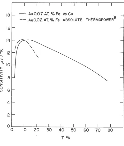
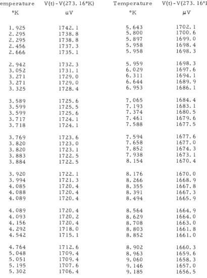
Results of the measurements (see Table I) are shown in Fig. 2.
The striking feature of this curve is its linearity over a long
tempera-ture range. It is this featempera-ture which strongly recommends Au-Fe
thermocouples as a secondary thermometer. This linear behavior is
shown even more clearly on Fig. 3. The sensitivity remains between
13. 5 and 14. 0 JJ.V
joK
all the way from 6 to 20°K. Even at 7 8°K thesensitivity has fallen only to 8 JJ.V /°K. For comparison we show in
Fig. 3 the sensitivity for Au 0. 02 at.
o/o
Fe (absolute thermopower). 8Note that the lower Fe concentration has a higher sensitivity at low
temperatures but it falls off more rapidly at high temperatures. This
reflects the fact that the magnetic ordering takes place at a lower
temperature for the smaller Fe concentrations. Different voltage
characteristics can be obtained by proper selection of the Fe
concen-tration. These Au-Fe thermocouples provide a quick. easy and
relia-ble method for determining temperatures to an accuracy of 0. 05°K in
Au 0.07 AT.% Fe vs Cu THERMOCOUPLE
1800
> 1600
::l
-
~0
~
[image:10.591.41.711.111.532.2]~ 1400
...
(\J
-
>
I
-
...
-
>
12001000
800L-________ L _ _ _ _ _ _ _ ~L---~~---~~---~---~---~--~
0 10 20 30 40 50 60
-.1 T °K
Fig. 2. Voltage plot for Au 0. 07 at.
o/o
Fe vs Cu thermocouple.8
18
16
14
~
12
0'
>
:i.
10
>-...
>
...
8
en
z
w
6
en
4
2
0
-
Au 0.0 7 AT.
0/o
Fe vs Cu
- - Au0.02 AT.
0/o
Fe
ABSOLUTE THERMOPOWER 8
0
20
30
40
50
60
70
80
Fig. 3. Sensitivity plots for Au 0. 07 at.
o/o
Fe vs Cu [image:11.595.115.514.173.644.2]REFERENCES
1R. Berman and D. J. Huntley,
Cryogenics~
70 (1963).2J. E. Kilpatrick, W. E. Keller and E. F. Hammel, Phys. Rev.
97, 9 (1955).
3 T. R. Roberts and S. G. Sydoriak, Phys. Rev. 102, 304 (1956).
4
G. W. Moessen, J. G. Aston and R. G. Ascah, Temperature,
Its Measurement and Control in Science and Industry, edited by C. M. 9
Herzfeld (Reinhold Publishing Corporation, New York, 1962), Vol. III,
p. 91.
5 J. Hilsenrath, C. Beckett, W. Benedict, L. Fano, J. Masi,
R. Nuttall, Y. Touloukian and H. Woolley, Tables of Thermodynamic
and Transport Properties of Air, Argon, Carbon Dioxide, Carbon
Monoside, Hydrogen, Nitrogen, Oxygen and Steam (Pergamon Press,
Inc., New York, 1960).
6
R. Berman and C. A. Swenson, Phys. Rev. 95, 311 (1954).7 F. G. Brickwedde, H. van Dijk, M. Durieux, J. R. Clement and
J. K. Logan, J. Res. Natl. Bur. Standards 64A, 1 (1960).
8
D. K. C. MacDonald, W. B. Pearson and I. M. Templeton,
10
Table I
Au-Fe vs Cu Thermocouple Calibration
Temperature
V(t)-V(273. l6°K)
Temperature
V(t)- V(273. l6°K)
OK
uv
OK
IJV
1.