
Innovative antifouling technologies: microtexture and metal
246
0
0
Full text
(2) Innovative antifouling technologies: microtexture and metal. Thesis submitted by Matthew John Vučko BSc, MSc In June 2014. for the degree of Doctor of Philosophy in the Centre for Sustainable Tropical Fisheries and Aquaculture School of Marine and Tropical Biology James Cook University.
(3) Statement on the contribution of others. Financial support for this research was provided by the School of Marine and Tropical Biology and the Graduate Research School of James Cook University (JCU), and the Commonwealth Scientific and Industrial Research Organisation (CSIRO). Stipend support was provided by JCU with a Postgraduate Research Scholarship and by CSIRO with a Postgraduate Studentship. My primary supervisor Rocky de Nys (JCU, Townsville, Queensland, Australia) and secondary supervisors Andrew Poole (CSIRO, Waurn Ponds, Victoria, Australia) and Peter King (CSIRO, Clayton, Victoria, Australia) provided intellectual guidance, financial support and editorial assistance. Mathew Vickers and Nicholas Paul (JCU, Townsville, Queensland, Australia) provided statistical support. Christina Carl (JCU, Townsville, Queensland, Australia) and Steve Whalan (Southern Cross University, Lismore, New South Wales, Australia) provided editorial assistance and helped with the culture of animals and with experimental assays (Chapters 2 and 3). Fiona Glenn and Brett Sexton (CSIRO, Clayton, Victoria, Australia) provided microtextured surfaces (Chapter 2) and Sue Horne provided photocatalytic matrices (Chapter 3). All work involving scanning electron microscopy, energy dispersive X-ray spectroscopy and atomic force microscopy was performed at the Advanced Analytical Centre (AAC) of JCU (Chapters 2 and 4).. ii.
(4) The work involving the focused ion beam scanning electron microscope was performed at the Melbourne Centre for Nanofabrication, which is the Victorian node of the Australian National Fabrication Facility, an initiative partly funded by the Commonwealth of Australia and the Victorian Government (Chapter 4). Peter King and Mahnaz Jahedi (CSIRO, Clayton, Victoria, Australia) produced all cold spray metal-embedded surfaces (Chapters 4, 5, 6 and 7). Yi Hu (AAC of JCU, Townsville, Queensland, Australia) analysed all water samples obtained for release rate measurements (Chapters 6 and 7). Finally, the Townsville Yacht Club provided their facilities for all field trials done throughout this research.. iii.
(5) Acknowledgements. Many amazing people have supported me and contributed to the success of this thesis and I have been very lucky to have such a great supervisory team, always enthusiastic and ready to help, each with strengths that complement the others. First and foremost, I would like to thank my primary supervisor Rocky de Nys. You have an unwavering ability to make the worst situation seem like a walk in the park. One meeting with you and my faith in research is restored. You have given me the skills and confidence to write effectively and become a scientist and no matter how busy you get, you always had time to meet, discuss and read whatever it is I had for you. I will forever be indebted and am very grateful to have been your student. Thank you to Andrew and Peter, my associate supervisors. They too have provided invaluable advice and support throughout this thesis. Andrew, you were always able to see things in a different perspective, while Peter, you helped me see the smaller side of things and taught me that sometimes the overall picture isn’t as important as is the miniscule details. Thank you to Tine, Hugh, Scott, Sarah, Pedro, Zou Zou, Ian, Marie, Kerri, Vero, Boer, Andrew and the ever changing de Nys lab group who have always been supportive. Special thanks to Michelle Condy for passing the reigns over to me and teaching me everything I needed to know to get started in this field. I would also like to thank many of the amazing people at James Cook University for helping me along the way. Ross Barrett from the workshop, Vince Pullella and Gordon Bailey ffrom IT, Simon Wever and Ben Lawes from MARFU, Stratis Manolis and Greg Jameson from the biological store, Julie Fedorniak from vehicles and Karen Wood. iv.
(6) from the finance office. Many thanks to the team at the Advanced Analytical Centre, Shane Askew, Kevin Blake and Yi Hu, for their expertise and help over the past three years. They have been essential to the success of the research found in this thesis. I would like to thank Mark Cruickshank, Jo Hassett and Kerri Hauser from the Townsville Yacht Club for their continued support over the years and Kevin Tilbrook from the Museum of Tropical Queensland for his invertebrate expertise. Thank you to Susan McGrath and Kristin Nunn for years of support and always having answers to my questions. I would also like to thank Lin Schwarzkopf for introducing me to Rocky. Without your recommendation I never would have started down this path. Thank you to all of the anonymous reviewers whose comments, criticisms and expertise in the field of biofouling improved each one of the manuscripts published from this thesis. Thank you to my family, especially my parents Mary and Steve, who have always been supportive throughout my postgraduate studies and my time away from Canada. Thank you to all my friends, from Australia and Canada, for years of friendship, good times and support through the not so good times. A special thanks to Betsy for her battery. Lastly, but certainly not least, thank you to my wife Anne. Having a child together while doing a PhD might seem like a challenge, but it has made me work harder than ever before never knowing what the next day will bring. Who knew something so small could have such a profound effect on one’s life, thanks for the good times Littleman. Anne, you have been by my side through it all and only you will know what I have truly gone through to accomplish this. Thank you for your love, support and encouragement, I could not have done it without you.. v.
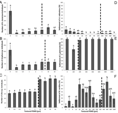
(7) Abstract. Fouling causes negative economic impacts to the major marine industries of shipping, aquaculture and geophysical exploration. Currently, the most widely used method to prevent the accumulation of fouling is copper-based biocidal antifouling paints. However, their deleterious impact on the marine environment and non-target organisms is driving the need to develop environmentally-sustainable antifouling technologies.. Innovative. antifouling. technologies. employing. microtexture,. photocatalysts and cold spray metal embedment are promising alternatives to current antifouling paints. This thesis investigates these alternative technologies to identify their efficacy across both niche and broad spectrum antifouling applications. In Chapter 2, a series of 18 textured (0.4–1,000 µm) and non-textured (0 µm) polydimethylsiloxane (PDMS) surfaces with round- and square-wave linear grating profiles were tested for their antifouling potential against the settlement of fouling organisms in the laboratory and in the field against the recruitment of a multi-species fouling community. In laboratory assays, Nitzschia closterium and Amphora sp. were deterred by all surface topographies regardless of texture periodicity. Settlement of Ulva sp. was lower on texture sizes less than propagule size, and settlement of Saccostrea glomerata and Bugula neritina was lower on texture sizes closest to, but less than, larval sizes. After the six month field trials, all textured surfaces lost their deterrent effect, however, the foul-release capabilities of textures were still present. High initial attachment was correlated with more fouling remaining after removal trials, indicating that fouling recruited in higher numbers to surfaces upon which they attached most strongly.. vi.
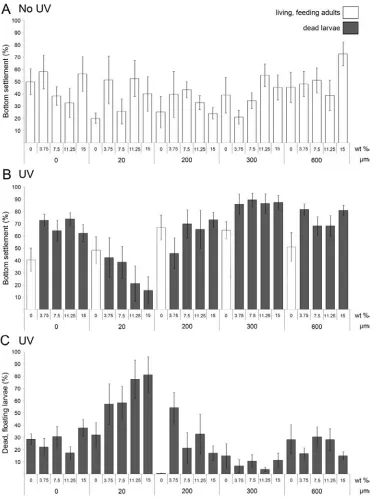
(8) In Chapter 3, the potential for a photocatalyst to enhance the antifouling properties of microtexture was examined. PDMS surfaces, textured with a square-wave linear grating profile (0, 20, 200, 300 and 600 µm), were embedded with a range of photocatalytic titanium dioxide (TiO2) nanoparticle loadings (3.75, 7.5, 11.25 and 15 wt%). The resulting surfaces were used to test the combined efficacy of these technologies as antifouling materials in the laboratory and in the field against the common fouling bryozoan, B. neritina. Settlement of B. neritina was quantified in the laboratory under two intensities of ultraviolet light. The lowest settlement rates were observed on 20 µm surfaces. However, texture effects were not as critical to larval settlement as the presence of TiO2. TiO2, in conjunction with ultraviolet light, completely inhibited larval metamorphosis even at the lowest loading (3.75 wt%) and the lowest intensity of ultraviolet light (24 W m-2). Recruitment of B. neritina during field trials showed similar results to laboratory assays. The lowest recruitment occurred on 20 and 200 µm surfaces, with recruitment being significantly lower on all surfaces containing TiO2. Therefore for B. neritina, although all TiO2 loadings were effective, 3.75 wt% can be used as a minimum inhibitory concentration to deter larval settlement and the addition of a 20 µm texture further increases the deterrent effect. In Chapter 4, the use of cold spray technology to give antifouling properties to thermoplastic polymers (polymers) by embedding metals known to prevent fouling was investigated. Two polymers, high-density polyethylene (HDPE) and nylon were metallised with copper powder using cold spray technology. After 250 days in the field, copper-embedded HDPE and copper plate controls were completely free of hard foulers compared to copper-embedded nylon and polymer controls which were heavily fouled with both soft and hard fouling. The success of copper-embedded polymers is related to the interaction between the properties of the polymers (elastic modulus and hardness) and the cold spray process which affect particle embedment depth, and subsequently, the release of copper ions as determined by analytical techniques. This chapter demonstrates that embedding metal particles using cold spray equipment is an effective antifouling technology for polymers, in particular those that are difficult to treat with standard copper-based biocide paints.. vii.
(9) Furthermore, efficacy is a function of the interaction between the cold spray metal and the polymer recipient. In Chapter 5, cold spray metal embedment was used to determine the effects of loading densities of metal particles on fouling. Antifouling efficacy under field conditions was quantified for low (22.1 ± 4.8 g m-2) and high (101.1 ± 10.8 g m-2) densities of copper particles embedded into polyurethane seismic streamer skins, which are used in geophysical exploration. Failure of each copper-embedded treatment was defined as settlement of hard foulers. Low-density streamers failed after 42 days while high-density streamers failed after 210 days. Most importantly, the high-density streamers were completely free of hard foulers including the barnacle Amphibalanus reticulatus during this time. In conclusion, cold spray metal embedment is an effective antifouling technology for polyurethane seismic streamer skins, under intense fouling conditions. Higher copper particle densities enhance antifouling longevity and the effect of density provides a tool to extend efficacy and enhance antifouling performance for specific polymers. Finally, in Chapter 6, loading density gradients of metal particles were investigated. Particles of copper, bronze and zinc metal were embedded into a polymer using cold spray technology to produce loading density gradients. The gradients were used to identify the species with the highest tolerance to the release of copper and zinc ions. The gradients also established the minimum effective release rates (MERRs) of copper and zinc ions needed to prevent the recruitment of fouling under field conditions. Watersipora sp. and Simplaria pseudomilitaris had the highest tolerance to the release of metal ions. Copper and bronze gradient tubes were similar in their MERRs of copper ions against Watersipora sp. (0.058 g m-2 h-1 and 0.054 g m-2 h-1, respectively) and against S. pseudomilitaris (0.030 g m-2 h-1 and 0.025 g m-2 h-1, respectively). Zinc was not an effective antifouling material with failure within two weeks. The cold spray gradients were effective in determining MERRs and these outcomes provide the basis for the development of cold spray surfaces with pre-determined life-spans using controlled MERRs.. viii.
(10) In summary, the research presented throughout this thesis describes innovative antifouling technologies that can be used as alternatives to current antifouling paints. In addition, this thesis identifies the efficacy of these technologies across niche and broad spectrum antifouling applications, while highlighting the importance of fieldbased trials. The incorporation of microtexture and a photocatalyst to already successful foul-release coatings, allows for further improvement of those materials. In addition, the use of cold spray technology as an innovative method to give antifouling properties to thermoplastic polymers has been thoroughly investigated and provides a promising avenue for future research and commercialisation. In conclusion, this thesis provides a significant contribution to the relatively new field of environmentallysustainable antifouling technologies and provides an innovative method to give antifouling properties to materials that previously, could not be protected against fouling.. ix.
(11) Table of contents. Statement on the contribution of others ................................................................................ ii Acknowledgements ................................................................................................................. iv Abstract ..................................................................................................................................... vi Table of contents ........................................................................................................................x List of tables ............................................................................................................................ xvi List of figures ........................................................................................................................ xviii Chapter 1: General introduction ..............................................................................................1 1.1. The progression of marine biofouling and its economic impact .........................1. 1.2. Past antifouling technologies ...................................................................................2. 1.3. Present-day antifouling technologies......................................................................4. 1.4. Alternatives to present-day antifouling technologies ..........................................6. 1.4.1. Microtextures ......................................................................................................7. 1.4.2. Photocatalysts .....................................................................................................9. 1.4.3. Cold spray metal embedment ........................................................................11. 1.5. x. Aims and chapter summaries ................................................................................12.
(12) Chapter 2: Using textured PDMS to prevent settlement and enhance foul-release of marine fouling organisms* ..................................................................................................... 15 2.1. Introduction .............................................................................................................. 15. 2.2. Materials and methods ........................................................................................... 17. 2.2.1. Production of textured PDMS surfaces ........................................................ 17. 2.2.2. Laboratory assays ............................................................................................ 22. 2.2.2.1. N. closterium and Amphora sp. .................................................................... 23. 2.2.2.2. Ulva sp. .......................................................................................................... 24. 2.2.2.3. A. reticulatus .................................................................................................. 24. 2.2.2.4. S. glomerata .................................................................................................... 25. 2.2.2.5. B. neritina ....................................................................................................... 25. 2.2.3. Field trials ......................................................................................................... 26. 2.2.4. Release trials ..................................................................................................... 27. 2.2.5. Statistical analysis ............................................................................................ 28. 2.3. Results ....................................................................................................................... 29. 2.3.1. Laboratory assays ............................................................................................ 29. 2.3.1.1. N. closterium and Amphora sp. .................................................................... 29. 2.3.1.2. Ulva sp. .......................................................................................................... 30. 2.3.1.3. A. reticulatus .................................................................................................. 30. 2.3.1.4. S. glomerata .................................................................................................... 31. 2.3.1.5. B. neritina ....................................................................................................... 32. 2.3.2. Field trials ......................................................................................................... 32. 2.3.3. Release trials ..................................................................................................... 37. 2.4. Discussion ................................................................................................................. 39. xi.
(13) Chapter 3: Combining a photocatalyst with microtopography to develop effective antifouling materials* ..............................................................................................................45 3.1. Introduction ..............................................................................................................45. 3.2. Materials and methods ............................................................................................47. 3.2.1. Production of TiO2–filled textured PDMS surfaces.....................................47. 3.2.2. Culture methods of B. neritina .......................................................................49. 3.2.3. Laboratory drop assays ...................................................................................49. 3.2.4. Field trials..........................................................................................................51. 3.2.5. Statistical analysis ............................................................................................52. 3.3. Results........................................................................................................................53. 3.3.1 3.3.1.1. Winter ............................................................................................................54. 3.3.1.2. Summer .........................................................................................................56. 3.3.2 3.4. Laboratory drop assays ...................................................................................53. Field trials..........................................................................................................59. Discussion .................................................................................................................61. Chapter 4: Cold spray metal embedment: an innovative antifouling technology* ........65 4.1. Introduction ..............................................................................................................65. 4.2. Materials and methods ............................................................................................68. 4.2.1. Polymer surface preparation ..........................................................................68. 4.2.2. Polymer surface characterisation ...................................................................69. 4.2.3. Polymer surface field trials .............................................................................71. 4.2.4. Statistical analysis ............................................................................................73. 4.3. 4.3.1. Polymer surface characterisation ...................................................................74. 4.3.2. Polymer surface field trials .............................................................................74. 4.4. xii. Results........................................................................................................................74. Discussion .................................................................................................................80.
(14) Chapter 5: Polyurethane seismic streamer skins: an application of cold spray metal embedment* ............................................................................................................................. 84 5.1. Introduction .............................................................................................................. 84. 5.2. Materials and methods ........................................................................................... 86. 5.2.1. Seismic streamer skin surface preparation................................................... 86. 5.2.2. Seismic streamer skin surface characterisation ........................................... 87. 5.2.3. Seismic streamer skin field trials ................................................................... 88. 5.2.4. Adhesion strength ........................................................................................... 89. 5.2.5. Statistical analysis ............................................................................................ 90. 5.3. Results ....................................................................................................................... 91. 5.3.1. Seismic streamer skin surface characterisation ........................................... 91. 5.3.2. Seismic streamer skin field trials ................................................................... 91. 5.3.3. Adhesion strength ........................................................................................... 95. 5.4. Discussion ................................................................................................................. 96. Chapter 6: Assessing the antifouling properties of cold spray metal embedment using particle concentration gradients*......................................................................................... 100 6.1. Introduction ............................................................................................................ 100. 6.2. Materials and methods ......................................................................................... 103. 6.2.1. Gradient tube surface preparation .............................................................. 103. 6.2.2. Gradient tube surface characterisation ....................................................... 105. 6.2.3. Initial release rates from gradient tubes ..................................................... 106. 6.2.4. Gradient tube field trials ............................................................................... 107. 6.2.4.1. MERR to prevent the recruitment of tolerant fouling species ............ 108. 6.2.4.2. Fouling through time ................................................................................ 109. 6.2.5 6.3. Statistical analysis .......................................................................................... 110 Results ..................................................................................................................... 113. 6.3.1. Gradient tube surface characterisation ....................................................... 113. 6.3.2. Initial release rates from gradient tubes ..................................................... 113. 6.3.3. Gradient tube field trials ............................................................................... 113. xiii.
(15) 6.4. 6.3.3.1. MERR to prevent the recruitment of tolerant fouling species .............113. 6.3.3.2. Fouling through time.................................................................................117. Discussion ...............................................................................................................123. Chapter 7: General discussion ..............................................................................................128 7.1. Chapter 2. Using textured PDMS to prevent settlement and enhance foul-. release of marine fouling organisms ...............................................................................128 7.2. Chapter 3. Combining a photocatalyst with microtopography to develop. effective antifouling materials..........................................................................................130 7.3. Chapter 4. Cold spray metal embedment: an innovative antifouling. technology ...........................................................................................................................131 7.4. Chapter 5. Polyurethane seismic streamer skins: an application of cold spray. metal embedment ..............................................................................................................132 7.5. Chapter 6. Assessing the antifouling properties of cold spray metal. embedment using particle concentration gradients......................................................133 7.6. Future considerations ............................................................................................134. References ...............................................................................................................................138 Appendix.................................................................................................................................162 Vucko MJ, Poole AJ, Carl C, Sexton BA, Glenn FL, Whalan S and de Nys R (2014). Using textured PDMS to prevent settlement and enhance release of marine fouling organisms. Biofouling 30: 1-16. Vucko MJ, Poole AJ, Sexton BA, Glenn FL, Carl C and de Nys R (2013). Combining a photocatalyst with microtopography to develop effective antifouling materials. Biofouling 29: 751-762. Vucko MJ, King PC, Poole AJ, Carl C, Jahedi MZ and de Nys R (2012). Cold spray metal embedment: an innovative antifouling technology. Biofouling 28: 239-248.. xiv.
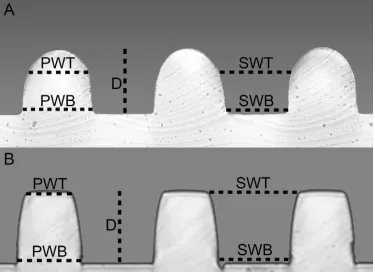
(16) Vucko MJ, King PC, Poole AJ, Jahedi MZ and de Nys R (2013). Polyurethane seismic streamer skins: an application of cold spray metal embedment. Biofouling 29: 1-9. Vucko MJ, King PC, Poole AJ, Hu Y, Jahedi MZ and de Nys R (2014). Assessing the antifouling properties of cold spray metal embedment using loading density gradients of metal particles. Biofouling 30: 651-666.. xv.
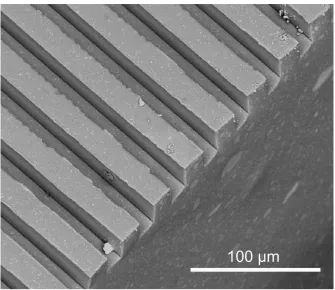
(17) List of tables. Chapter 2 Table 2.1. Topographical measurements of textured PDMS surfaces with round- and square-wave linear grating profiles. ...........................................................................22 Table 2.2. The antifouling effectiveness of a range of textured and non-textured PDMS surfaces were tested against common fouling organisms representing the spectrum of size ranges within a fouling community. .............................................23 Table 2.3. One-factor PERMANOVA analyses with significant effects of textured and non-textured PDMS surfaces on the settlement of fouling organisms (N. closterium, Amphora sp., Ulva sp., A. reticulatus, S. glomerata and B. neritina) in the laboratory. .......................................................................................................................32 Table 2.4. One-factor PERMANOVA analyses with significant effects of textured and non-textured PDMS surfaces as well as submersion depth (covariate) on total fouling coverage, total hard fouling coverage and recruitment of hard foulers (H. elegans, A. reticulatus, P. imbricata and B. neritina) after six months in the field. ...35. Chapter 3 Table 3.1. Two-factor PERMANOVA analysis with significant effects of surface texture (0, 20, 200, 300 and 600 µm) and TiO2 loading (0, 3.75, 7.5, 11.25 and 15 wt%) on the settlement of B. neritina on PDMS surfaces after 24 hours under winter and summer light regimes exposed and not exposed to UV. .....................56 Table 3.2. Two-factor PERMANOVA analysis with significant effects of surface texture (0, 20, 200, 300 and 600 µm) and TiO2 loading (0, 3.75, 7.5, 11.25 and 15 wt%) on the settlement of B. neritina and H. elegans on PDMS surfaces after 28 days under field conditions..........................................................................................59. xvi.
(18) Chapter 5 Table 5.1. Two-factor PERMANOVA analysis with significant effects of position (back, front) and copper density (no copper, low-density, high-density) on the settlement of fouling on seismic streamer skins after 42 and 210 days of continuous exposure in the field. ................................................................................ 95. Chapter 6 Table 6.1. Elemental characterisation of metal powders used for cold spray metal embedment of HDPE tubes........................................................................................ 104 Table 6.2. Statistical analyses surrounding the effects of copper, bronze and zinc metal particle gradients on fouling species.. ...................................................................... 116 Table 6.3. Two- and three-factor PERMANOVA analyses with effects of section, treatment and week on the recruitment of fouling species on copper, bronze and zinc gradient tubes as compared to HDPE controls. .............................................. 119. xvii.
(19) List of figures. Chapter 2 Figure 2.1. Cross sections of PDMS surfaces illustrating the topographical patterns of linear gratings using atomic force microscopy (A–E, scale bars = 1 µm; F, scale bar = 5 µm) and a compound microscope at 40x (G–L; scale bars = 50 µm) and 5x (M–R; scale bars = 500 µm) magnification. ................................................................20 Figure 2.2. Standard measurement locations characterising textured PDMS surfaces used in laboratory assays and field trials against marine fouling organisms.. .....21 Figure 2.3. The effect of textured and non-textured PDMS surfaces on the settlement of various fouling organisms under laboratory conditions.. .......................................31 Figure 2.4. Total fouling coverage (soft and hard fouling) on (A) textured and nontextured PDMS surfaces and overall at (B) different submersion depths after six months in the field. ........................................................................................................33 Figure 2.5. The effect of textured and non-textured PDMS surfaces on the recruitment of hard foulers at different submersion depths after six months in the field. ......36 Figure 2.6. Correlation between initial fouling after six months in the field and remaining fouling after being sprayed with a high-pressured water jet (75.9 kPa).. .......................................................................................................................38. xviii.
(20) Chapter 3 Figure 3.1. Backscattered SEM image of TiO2-embedded (7.5 wt%) textured PDMS (20 µm) showing the linear grating with a square-wave profile and mark-space ratio of 1.0 (groove width = land area width. ..................................................................... 49 Figure 3.2. Drop assay settlement outcomes for B. neritina larvae. .................................. 51 Figure 3.3. Mean settlement (± S.E.) of B. neritina in response to different TiO2 loadings (0, 3.75, 7.5, 11.25 and 15 wt%) on textured (20, 200, 300 and 600 µm) and nontextured (0 µm) PDMS under the winter UV light regime...................................... 55 Figure 3.4. Mean settlement (± S.E.) of B. neritina in response to different TiO2 loadings (0, 3.75, 7.5, 11.25 and 15 wt%) on textured (20, 200, 300 and 600 µm) and nontextured (0 µm) PDMS under the summer UV light regime................................... 58 Figure 3.5. Mean recruitment (± S.E.) of (A) B. neritina and (B) H. elegans in response to different TiO2 loadings (0, 3.75, 7.5, 11.25 and 15 wt%) on textured (20, 200, 300 and 600 µm) and non-textured (0 µm) PDMS after 28 days in the field. .............. 60. Chapter 4 Figure 4.1. Backscattered scanning electron micrographs of polymers embedded with copper particles using cold spray technology. .......................................................... 71 Figure 4.2. Fouling response to different metals, polymers and metallised polymer surfaces after 181 (A–C) and 250 (D–F) days in the field......................................... 77 Figure 4.3. Cu-embedded polymers analysed using FIB/SEM after 250 days in the field under heavy fouling conditions. ................................................................................. 78 Figure 4.4. EDS spectra of the patina from cold-sprayed polymer plugs after 250 days in the field under intense fouling conditions. (A) Cu-embedded HDPE. (B) Cuembedded nylon. ........................................................................................................... 79. xix.
(21) Chapter 5 Figure 5.1. PU seismic streamer skin sections were embedded with copper particles using cold spray technology to produce low- and high-density treatments. .......88 Figure 5.2. Digital microscopy images of PU streamers embedded with copper particles using cold spray technology. .......................................................................89 Figure 5.3. Fouling response to PU seismic streamer skins embedded with different densities of copper (low, high) and facing different directions (front- and backfacing) after 42 (A,B,C) and 210 (D,E,F) days in the field. .......................................94. Chapter 6 Figure 6.1. Black HDPE tubes embedded with copper, bronze and zinc metal particles (< 50 µm diameter) using cold-spray technology.. .................................................105 Figure 6.2. Plugs used for metal ion release rate measurements were removed from an unfouled portion of the gradient tubes adjacent the leading edge of fouling ....110 Figure 6.3. Gradient tube surface characterization examining metal particle surface area coverage and initial metal ion release rates (from low to high loading density of metal particles). .........................................................................................112 Figure 6.4. Recruitment of the most tolerant fouling species, Watersipora sp., on HDPE tubes embedded with a gradient of metal particles. ..............................................114 Figure 6.5. Recruitment of the second most tolerant fouling species, S. pseudomilitaris, on HDPE tubes embedded with a gradient of metal particles.. ............................117 Figure 6.6. Recruitment of Watersipora sp. over time on HDPE tubes with and without embedment of metal particle gradients. ...................................................................118 Figure 6.7. Recruitment of S. pseudomilitaris over time on HDPE tubes with and without embedment of metal particle gradients. ....................................................120 Figure 6.8. Recruitment of all fouling over time on HDPE control tubes, without embedment of metal particles. ...................................................................................122. xx.
(22) Chapter 1 General introduction. 1.1 The progression of marine biofouling and its economic impact Marine biofouling (fouling) is characterised by the accumulation of biological communities on surfaces submerged in seawater (Briand 2009). These communities include soft fouling species such as bacteria, diatoms and algae, and hard fouling species such as bryozoans, tubeworms, barnacles and mussels (Prendergast 2010). A variety of factors and processes facilitate the settlement (attachment of fouling larvae) and recruitment (any stage after settlement) of marine fouling. They include surface texture (Aldred and Clare 2008; Scardino et al. 2008; Long et al. 2010; Scardino and de Nys 2011), surface wettability (Dahlström et al. 2004; Zhang et al. 2005; Bennett et al. 2010), elastic modulus of the surface (Chaudhury et al. 2005), submersion depth of the surface (Cowie 2010), surface colour (Swain et al. 2006; Carl et al. 2011), physical, chemical and biological surface-associated cues (Pawlik 1992; Huang and Hadfield 2003; Dahlström et al. 2004; Qian, Xu, and Fusetani 2010), species availability depending on geographic location (Canning-Clode and Wahl 2010), the presence of conspecifics (Elbourne et al. 2008), seasonality (Jenkins and Martins 2010) and environmental conditions such as salinity, flow rate, temperature, ultraviolet irradiation and nutrient availability (Prendergast 2010). The process of fouling in a natural environment results in a complex three-dimensional community that will continue to develop and change, with ongoing settlement and recruitment of fouling, until the surface is removed from the water. Regardless of this complexity one thing remains consistent, fouling in the marine environment causes substantial negative impacts when it occurs on artificial structures made by humans.. 1.
(23) Fouling causes negative effects on water intakes for power stations and desalination plants (Henderson 2010) as well as offshore oil and gas platforms (Page et al. 2010) and the deep sea structures associated with them (Apolinario and Coutinho 2009). Fouling also impedes the functional capacity of vessels (Edyvean 2010; Schultz et al. 2011), aquatic infrastructure associated with aquaculture (de Nys and Guenther 2009; Fitridge et al. 2012) and structures used within the geophysical exploration industry (Vignaux 2010; Harrick and Stenzel 2011; Poole et al. 2012). Fouling on the hull of a ship will increase roughness which will subsequently increase hydrodynamic drag and therefore fuel consumption and lateness penalties (Townsin 2003; Schultz et al. 2011). Fouling on cages and netting used in aquaculture causes decreases in cage volume, flow and buoyancy while it increases physical damage and deformation as well as cage weight and therefore mooring stress (Braithwaite and McEvoy 2005; Fredriksson et al. 2007; Moe et al. 2009; Fitridge et al. 2012). Finally, fouling on seismic streamers skins, used to protect sensitive electronic equipment in geophysical exploration, causes reductions in seismic data quality and increases in equipment failure, feedback noise, hydrodynamic drag and therefore fuel consumption (Harper 1995; Vignaux 2010; Harrick and Stenzel 2011). The negative impacts associated with fouling have existed for thousands of years; for as long as humans have been using the marine environment. Consequently, attempts to deter and control the problem of fouling using antifouling technologies have also existed from the first uses of the marine environment.. 1.2 Past antifouling technologies Written records exist from as early as the 5th century B.C. citing treatments to mitigate the negative effects of fouling on ships, however, the search for suitable antifouling solutions most likely began even earlier (reviewed in WHOI 1952a; Yebra et al. 2004). Early treatments used to prevent fouling consisted of coating the bottoms of ships in pitch, wax, tar and asphalt as well as arsenic and sulphur mixed with oil (reviewed in Callow 1990). Lead sheathing was introduced in the 3rd century B.C., and between the. 2.
(24) 16th and 18th centuries was the most common form of ship cladding, even though it was not an effective deterrent against fouling in general, but mainly protected against marine borers (Yebra et al. 2004). The first successful form of antifouling was copper sheathing, and its use brought an end to earlier, unsuccessful antifouling treatments. Although copper was suggested as an antifoulant in 1625 in a patent presenting a mixture of a copper substance, cement and powdered iron, the first trial properly documenting the deterrent effect of copper, in the form of sheathing, was in 1758 on a warship in the British Navy (WHOI 1952a). After the success of that trial, copper sheathing was widely used in the British Navy for the next 40 years. At the end of the 18th century, the increasing use of iron ships led to the cessation of the use of copper sheathing due to its corrosive effects on iron, as well as a renewed necessity to find effective antifouling treatments (WHOI 1952a). Many alternatives were suggested, the most promising of which were paints consisting of an antifoulant such as copper oxide or mercury oxide, and a solvent such as turpentine or benzene which were bound together using resin or shellac varnish (Yebra et al. 2004). These formulations led to the production of modern-day antifouling paints, which were able to prevent fouling for up to 18 months by the early 1900’s (WHOI 1952a). In the 1950’s, these paints were further improved by the incorporation of organotins, within which the tri-butyl-tin (TBT) functional group was extremely effective at preventing fouling due to its strong biocidal activity towards a range of fouling organisms (Dubey and Roy 2003; Yebra et al. 2004). Initially, TBT was only available within an insoluble polymer matrix which lasted for 18 months prior to failure with the recruitment of fouling. The introduction of TBT within a soluble polymer matrix improved the paint as an antifoulant; but it was not efficient under low flow conditions, and the solubility of the paint caused it to erode too quickly at high speeds (Yebra et al. 2004). This led to the formulation of a TBT selfpolishing copolymer which allowed a controlled release of TBT, where pigment particles eroded to continually expose the surface underneath, producing a polishing effect (Kiil et al. 2001; Chambers et al. 2006). The result of this polishing was a reduction in the roughness of the hull which led to a reduction in fuel consumption. 3.
(25) and emissions as well as direct savings of more than two billion USD a year globally (Abbott et al. 2000; Champ 2000; Almeida et al. 2007). By the 1980’s, the TBT selfpolishing copolymer was used on more than 80% of the world’s commercial fleet (Abbott et al. 2000). The TBT self-polishing copolymer was one of the most successful antifouling coatings in history with the caveat that it was extremely toxic towards nontarget organisms and the broader environment, both of which have been widely documented (reviewed in Champ 2000; Terlizzi et al. 2001). For example, in addition to TBT’s acute toxicity to fouling organisms and fish (Martin et al. 1989; Dubey and Roy 2003), it is also persistent in sediment (MacGuire 2000), causes sterilization, imposex, reduced reproduction and deformations in molluscs (Bryan et al. 1987; Alzieu 1991), and has a high affinity for bioaccumulation in non-target organisms (Weidenhaupt et al. 1997; MacGuire 2000). These negative effects forced a total ban of TBT on ships < 25 m in length and a restriction on the release rates of compounds containing TBT by 2008 (Champ 2001; Yebra et al. 2004). Consequently, there was a renewed urgency to find a suitable alternative in the form of a tin-free antifouling coating.. 1.3 Present-day antifouling technologies Presently, the most widely used antifouling products are paint formulations that consist of copper oxide, which is soluble in seawater, combined with an organic booster biocide (Brooks and Waldock 2009; Finnie and Williams 2010). The toxicity of copper in marine invertebrates occurs directly through the absorption of waterborne free Cu+ and Cu2+ ions, arguably the most toxic form of the metal (Pinho et al. 2007; Brooks and Waldock 2009; Thomas and Brooks 2010). The mechanism of toxicity of copper is associated with the inhibition of the activity of the carbonic anhydrase enzyme, impairing gas exchange and acid–base regulation, and the inhibition of Na+and K+-ATPase activity, causing intracellular ion imbalances (Grosell et al. 2007; Lopes et al. 2011). However, copper is only effective within the boundary layers of the antifouling surface, and is less toxic when released into the environment as a result of. 4.
(26) the complexation of copper with dissolved organic carbon in the water column and a low bioavailability of copper within sediments (Voulvoulis et al. 1999; Lu and Allen 2001; Brooks et al. 2008; Brooks and Waldock 2009; Thomas and Brooks 2010). In addition, the leaching of copper from antifouling coatings into the natural environment comprises only ~1% of the total influx, the rest of which comes from natural weathering of the land (Brooks and Waldock 2009). Therefore, apart from enclosed harbours where the release of copper from many stationary vessels may reach unacceptable levels, the use of copper alone is acceptable for the purposes of antifouling. Copper ions are effective against a broad range of fouling organisms, though hard fouling species such as barnacles and tubeworms are more susceptible to the toxicity of copper than soft fouling species such as diatoms and algae (Finnie and Williams 2010). Therefore, to prevent species which may be tolerant to lower release rates of copper ions,. paint formulations have been improved by incorporating booster. biocides (Voulvoulis et al. 1999). Currently, approximately 18 biocidal compounds are in use worldwide but for many of these compounds, especially those that are not readily available, there is limited data describing their long-term effects on the aquatic environment (Thomas 2009). For biocides that are most commonly used, there is substantial variation in the chemical and physical properties surrounding their toxicity to fouling, toxicity to non-target organisms, leaching rates, solubility and persistence in the environment (reviewed in Thomas 2009). For example, Irgarol 1051 and Diuron both disrupt the photosynthetic process in algae and are toxic to non-target organisms (Liu et al. 1999; Voulvoulis et al. 1999; Evans et al. 2000; Giacomazzi and Cochet 2004; Yebra et al. 2004). However, Irgarol 1051 has higher leaching rates with lower solubility, and a longer half-life in marine sediments compared to Diuron (Tóth et al. 1996; Thomas 2009). The diversity in initial chemical properties and deleterious effects on the marine environment and non-target organisms has resulted in restrictions and bans which vary for each of the 18 biocides depending on geographic location and legislation of the accompanying country (Thomas 2009).. 5.
(27) In addition to the obvious concerns surrounding the booster biocides, a further drawback to copper-based biocide paints is their poor adhesion to thermoplastic polymers. Marine industries, including aquaculture and geophysical exploration, which rely on the use thermoplastic polymers, cannot employ copper-based biocide paints, which are designed for inflexible surfaces. Instead, cages and netting used in aquaculture, produced using high-density polyethylene and nylon are coated in flexible waxy emulsions incorporating copper. The typical life span of these waxy emulsions prior to failure is between 6 to 9 months, much shorter than copper-based biocide paints which have a lifespan of approximately 36 months (reviewed in Braithwaite and McEvoy 2005; Braithwaite et al. 2007; de Nys and Guenther 2009; Finnie and Williams 2010; Guenther et al. 2010). In addition, no functional coatings exist for seismic streamers where polyurethane, which is relatively soft, flexible and hydrophobic, is handled mechanically during operation on specialised exploration vessels (Poole et al. 2012).. 1.4 Alternatives to present-day antifouling technologies Issues with copper-based biocide paints have led to the conceptualisation and testing of many alternative environmentally-sustainable antifouling treatments (Omae 2003; Callow and Callow 2011). Here, microtexture, photocatalysts and cold spray metal embedment are introduced and examined for their potential as antifouling technologies, which are the focus of subsequent chapters of this thesis. The need for non-toxic alternatives to booster biocides has shifted the focus of antifouling technologies from examining the chemical properties of a surface to examining the physical properties of a surface. By manipulating the physical properties of a surface, it can be less desirable to fouling or reduce the attachment strength of fouling making it easier to remove (Callow and Callow 2009). These surface-based technologies are the most promising alternative (Webster and Chisholm 2010) and rely on the modification of structural, mechanical and polarization properties of a surface in an effort to maximise the antifouling or foul-release capabilities of the material (Rosenhahn et al.. 6.
(28) 2008). In addition, photocatalysis is a potential broad-spectrum alternative to enhance surface-based technologies. In the marine environment, photocatalysts can cause a decrease in larval adhesion strength and even mortality of the larvae of macrofouling organisms (Carl et al. 2012b). Although they have the potential to negatively affect settling organisms, they are not persistent in the environment and are unlikely to affect non-target organisms (Bhatkhande et al. 2002). Nevertheless, they are not currently used in marine antifouling and offer a promising avenue as a broad spectrum antifouling technology which can prevent the formation of biofilms and the settlement of a range of marine fouling organisms. Finally, the need to develop new antifouling treatments for thermoplastic polymers has led to the investigation of cold spray metal embedment, a relatively new innovation (Papyrin et al. 2007). Cold spray technology is used to embed small amounts of pure metal particles into thermoplastic polymers without compromising polymer properties (Poole et al. 2012; Vucko et al. 2012; Chapter 4). The use of metal to prevent fouling is not a new concept, as has been discussed previously however, by applying pure metal particles that are known to prevent fouling, thermoplastic polymers can be given antifouling properties while maximising longevity.. 1.4.1 Microtextures The manipulation of surfaces for the purpose of antifouling has been examined extensively with the modification of elastic modulus (Brady and Aronson 2003; Chaudhury et al. 2005), charge (Rasmussen and Østgaard 2001; Petrone et al. 2011), amphiphilicity (Joshi et al. 2009; Martinelli et al. 2012), wettability (Finlay et al. 2002; Aldred et al. 2006; Carman et al. 2006; Petrone et al. 2011; Carl et al. 2012a; Bloecher et al. 2013; Di Fino et al. 2014) and microtexture (Callow et al. 2002; Schumacher et al. 2007a; Schumacher et al. 2007b; Carl et al. 2012a). These studies have provided the foundation from which we can further advance our understanding of the parameters contributing to larval settlement. Ultimately, a combination of these properties will be needed to successfully develop materials that are effective. Yet isolating specific surface properties and investigating their effects alone is fundamental to. 7.
(29) understanding their relative importance when combining properties for the ultimate antifouling or foul-release material. Currently, foul-release coatings, which are being applied commercially (Townsin and Anderson 2009), are produced using materials with low surface energies such as silicone elastomers and fluoropolymers (Webster and Chisholm 2010). To date, the most successful of the foul-release materials is polydimethylsiloxane (PDMS; Anderson et al. 2003). Although, these coatings do not necessarily prevent the settlement of fouling, the low-surface energy of the material makes it easier to remove fouling after settlement with the use of hydrodynamic shear forces (Kavanagh et al. 2005; Wendt et al. 2006; Finnie and Williams 2010). However, these coatings are only effective for organisms that adhere poorly and are easily removed (Finlay et al. 2002; Bennett et al. 2010), while other organisms attach well, making removal more difficult (Finlay et al. 2002; Finlay et al. 2010). In addition, foul-release coatings are not suitable for slow-moving vessels or stationary marine structures due to their dependence on hydrodynamic forces. Therefore, to improve the efficacy of foul-release coatings, incorporating microtexture into a known foul-release material may enhance the antifouling and foul-release capabilities of that material. Microtexture is a key element affecting the settlement of marine fouling invertebrates (Bers and Wahl 2004; Long et al. 2010; Scardino and de Nys 2011). The physical component of a surface provides contact points that facilitate attachment, settlement, and in many cases metamorphosis. There is a positive correlative effect between the number of attachment points available on a surface and the settling success of fouling organisms (Callow et al. 2002; Scardino et al. 2006; Scardino et al. 2008). This has been demonstrated for diatoms (Scardino et al. 2006), algae (Callow et al. 2002; Schumacher et al. 2007a; Schumacher et al. 2007b), bryozoans (Scardino et al. 2008), tubeworms (Scardino et al. 2008), barnacles (Berntsson et al. 2000; Schumacher et al. 2007b; Aldred et al. 2010; Chaw et al. 2011) and mussels (Carl et al. 2012a). Generally, fouling larvae are deterred by microtextures with widths that are slightly smaller than the smallest dimension of the fouling larvae. This results in a smaller area that the organism can interact with and a fewer number of attachment points (Callow et al. 2002; Scardino et 8.
(30) al. 2006; Scardino et al. 2008). A smaller interaction area means that larvae will not be in complete contact with the surface and consequently, will not be able to use the full potential of their adherence mechanism. Therefore, ‘attachment point theory’ provides an avenue to deter the settlement of fouling or enhance the foul-release capabilities of a surface by reducing the number of attachment points. Conversely, the deterrent effect of surface-based technologies involving microtexture can be diminished when the number of available attachment points increases, occurring once the surface has become conditioned and overgrown by organisms that are too small to be affected (Molino and Wetherbee 2008; Molino et al. 2009a; Molino et al. 2009b; Bers et al. 2010; Terlizzi and Faimali 2010; Zargiel et al. 2011; Martinelli et al. 2012). Therefore, textured surfaces that work well against specific fouling organisms in laboratory assays can lose their deterrent effects in the field against the intense fouling pressures of a natural, multi-species fouling community. However, although the deterrent effect of those textures may be lost, their underlying foul-release capabilities may still be present. To date, a majority of the literature investigating the effects of microtexture focus on controlled, short-term laboratory assays (Schumacher et al. 2007b; Scardino et al. 2008; Aldred et al. 2010; Cooper et al. 2011; Carl et al. 2012a). In contrast, there is a paucity of comparisons between successful laboratory assays and the performance of textured surfaces exposed to natural fouling communities for longer periods (Thomason et al. 2002; Bers and Wahl 2004), highlighting the importance of field trials.. 1.4.2 Photocatalysts Phototcatalysis is a chemical oxidation process activated by light which generates reactive oxidising agents, including hydroxyl radicals (Fujishima et al. 2008). Hydroxyl radicals have an oxidising power greater than ozone and second only to fluorine (dos Santos et al. 2007) and are able to react with organic molecules and biological substrates at rates close to diffusion limits (Bhatkhande et al. 2002). Photocatalytic technology is used in antifouling membranes (Choi et al. 2007; Madaeni and Ghaemi 2007), heat exchange surfaces (Gopal et al. 2007), self-sterilising and self-cleaning. 9.
(31) surfaces (Fujishima and Zhang 2006; Fujishima et al. 2008), as well as air and water remediation often with the mineralisation of toxic and recalcitrant organic compounds (Bhatkhande et al. 2002; Gogate and Pandit 2004; Choi et al. 2007; Demeestere et al. 2007). In addition, photocatalysts are lethal to bacteria, fungi, viruses, prions, protozoans, spores, oocysts and cancer cells due to non-specific decomposition and mineralisation (Watts et al. 1995; Lonnen et al. 2005; Xu et al. 2007; Paspaltsis et al. 2009; Zhao et al. 2009). In general, photocatalysts are semi-conductor metal oxides such as TiO2, ZnO, WO3, CdS, ZnS, SrTiO3 and SnO2 (Bhatkhande et al. 2002). Of these, titanium dioxide (TiO2) is regarded as an ideal photocatalyst due to its low cost, high energy, abundance, corrosion resistance and chemical safety (Aprile et al. 2008). When TiO2 is activated by light of sufficient energy, which in environmental applications is sunlight, a photo-excited electron in the valence band is promoted to the conduction band (Wang et al. 2007; Gaya and Abdullah 2008) resulting in the formation of a positive hole in the valence band and an electron in the conduction band creating a hole–electron pair (Fujishima et al. 2008). The conduction band electron reduces molecular oxygen to form superoxide radicals, which either react to form hydroxyl radicals or oxidise target compounds directly (Demeestere et al. 2007; Gaya and Abdullah 2008). In the absence of suitable electron and hole scavengers, the stored energy is dissipated within a few nanoseconds by recombination (Bhatkhande et al. 2002). Although human safety concerns have been raised about the nanoparticulate form (Long et al. 2007), the high reactivity of the radicals formed makes them safe for use, since the photokilling zone is restricted to the near-surface of the material, and they are not persistent in the environment and therefore unlikely to react with nontarget organisms. Although photocatalysts have the potential to negatively affect fouling by degrading conditioning molecules, settlement cues and extracellular polysaccharide glues, they are currently not used as marine antifoulings. By introducing TiO2 into a microtextured PDMS matrix, the combined efficacy of both technologies can be tested with the added advantage that the mechanical properties of silicone elastomers can be improved with the incorporation of the photocatalyst (Mirabedini et al. 2008).. 10.
(32) 1.4.3 Cold spray metal embedment Cold spray is a metal spray process whereby solid metal particles (typically ˂ 50 µm) are accelerated to supersonic velocities in an inert gas flow and deposited onto a substratum surface to form a coating (Stoltenhoff et al. 2002; Papyrin et al. 2007). Gas is accelerated using high pressure and heat (less than the melting point of the metal being used) and once stabilised, particles are injected into the gas flow and pass through a converging-diverging nozzle and onto the surface (Gärtner et al. 2006). Many factors can be manipulated during the cold spray process (nozzle type, nozzle dimensions, gas type, gas temperature, powder size, powder flow rate, powder insertion location and dimensions), and the appropriate balance depends largely on the type of metal powder being used and the substratum being sprayed (Pattison et al. 2007; Lupoi and O’Neill 2011). This balance must be maintained throughout the cold spray process in order to allow particles to surpass a critical velocity where, instead of rebounding off intended substratum at low velocity, or abrading at moderate velocity, particles embed or adhere to the surface. Heating of the gas not only increases velocity but also enhances plasticity of the metal particles, enabling effective deposition and heat transfer to the surface, which may improve embedment into the substratum. Applications of cold spray are very broad and include the formation of wear- and corrosion-resistant coatings, improvement of electrical and heat conductivity (Gärtner et al. 2006), freeform shape production without the use of moulds, and structure reinforcement (Pattison et al. 2007). Cold spray is ideal in these situations due to the dense nature of the deposits and the absence of defects such as material stress and warping, substandard mechanical properties, and changes in microstructure caused by excessive heating or melting of the particles, seen with competing thermal spray techniques (Amon et al. 1993; Gärtner et al. 2006; Pattison et al. 2007). The use of cold spray technology as a method to control fouling, by embedding metal particles known to prevent fouling (i.e. copper) into polymers, is an innovative approach and has the potential to deliver new antifouling materials.. 11.
(33) 1.5 Aims and chapter summaries The overall aims for this thesis were to investigate innovative antifouling technologies using microtexture, photocatalysts and cold spray metal embedment as potential alternatives to present antifouling technologies. Microtexture, used in conjunction with a foul-release material, has been examined thoroughly in the past but generally in the context of laboratory assays alone. Here, laboratory assays are done in conjunction with field trials to establish links between the two. Furthermore, incorporating a photocatalyst into texture is examined in the context of antifouling to investigate the combined efficacy of both these technologies. Finally, although metals have been used in the past and are used presently in paints and emulsions, here, pure metal powders are embedded into thermoplastic polymers using cold spray technology, and examined as a potential antifouling alternative. Chapter 2 examines the antifouling and foul-release efficacy of 18 textures (0– 1,000 µm) incorporated into PDMS, against the settlement and recruitment of fouling organisms in the laboratory and in the field, respectively. Short-term laboratory assays were done to establish the settlement patterns of fouling taxa representing the spectrum of size ranges of settling organisms within a natural fouling community. Long-term field trials were done to examine the deterrence of recruitment of fouling organisms as well as the foul-release properties exhibited by the textures. The importance of conducting long-term field trials in conjunction with short-term laboratory assays, as well as the ability of a surface to maintain its foul-release properties, is discussed. Chapter 3 investigates the potential to produce an effective antifouling technology by combining microtexture with a photocatalyst. PDMS incorporating five textures (0– 600 µm) was combined with a range of photocatalytic TiO2 nanoparticle loadings (0– 15 wt%) and tested in the laboratory and in the field against a common fouling bryozoan. Laboratory assays examined the effects of summer versus winter ultraviolet radiation while field trials, undertaken when the bryozoans were most prevalent, quantified the effects of microtexture and TiO2 in the natural environment. The. 12.
(34) interaction between microtexture and TiO2 loading, with respect to ultraviolet radiation strength, and the effects on the settlement and recruitment of the fouling bryozoan is discussed. Chapter 4 examines for the first time, the embedment of metal powder into thermoplastic polymers using cold spray technology to determine the potential of this technology as an effective deterrent against fouling organisms. Two thermoplastic polymers embedded with copper powder were trialled for 250 days under field conditions to quantify their efficacy as antifouling materials. At the end of the field trial, analytical techniques were used to determine the differences in the structure of individual particles and the overall composition of the copper-embedded surfaces. The efficacy of antifouling, which is a function of the interaction between the metal powder and the thermoplastic polymer recipient, is discussed. Chapter 5 examines an application of cold spray technology, where antifouling properties were given to polyurethane seismic streamer skins by embedding copper particles. The geophysical exploration industry uses seismic streamers to protect sensitive electronic equipment which measure seismic feedback data while being towed at moderate speeds (4–5.5 knots). There are no functional antifouling coatings for seismic streamer skins due to the technical constraints associated with application procedures and to the mechanical handling of the streamers during operation. Therefore, the streamers were embedded with copper powder using different loading densities of copper particles to determine antifouling longevity under field conditions. In addition, upon failure of the surfaces with the recruitment of fouling, streamers were exposed to realistic flow to establish whether they have foul-release capabilities. The effects of density loading of copper particles on antifouling efficacy are discussed. Chapter 6 investigates the minimum effective release rates of copper and zinc ions from metal-embedded polymers needed to prevent the recruitment of fouling under field conditions. This Chapter also examines which species, from a natural fouling community, had the highest tolerance to copper and zinc ions and which species were most easily deterred by these metal ions. Minimum effective release rates were 13.
(35) established by producing copper-, bronze- and zinc-embedded thermoplastic polymer tubes, using cold spray technology, with a loading density gradient of metal particles ranging from low to high densities. In addition, the release rates of copper ions from copper- and bronze-embedded tubes were quantified to establish whether these metals could be used interchangeably. The use of gradients to determine minimum effective release rates as well as the effect of release rates of metal ions on the recruitment of fouling organisms is discussed. Chapter 7 presents a summary and discussion of the results while examining future directions for the use of microtexture and photocatalytic materials as antifoulants and for the improvement of cold spray metal embedment technology for use with thermoplastic polymers.. 14.
(36) Chapter 2 Using textured PDMS to prevent settlement and enhance foul-release of marine fouling organisms*. 2.1 Introduction Biofouling is the settlement of fouling organisms to submerged surfaces and results in significant economic and environmental problems. In the marine environment, it impedes the functional capacity of vessels (Edyvean 2010; Schultz et al. 2011) and aquatic infrastructure associated with aquaculture (de Nys and Guenther 2009; Fitridge et al. 2012), offshore oil and gas platforms (Page et al. 2010) geophysical exploration (Vignaux 2010; Harrick and Stenzel 2011) and water intakes for power stations and desalination plants (Henderson 2010). Larval settlement of marine fouling organisms onto these surfaces is an essential step towards the establishment of fouling communities and is facilitated by biological, physical and chemical surface-associated cues (Rittschof et al. 1998; Clare and Aldred 2009). The larval settlement phase is therefore a primary target in the development of effective antifouling solutions to mitigate the economic costs associated with biofouling. Traditionally, successful antifouling technologies have incorporated metal or organic biocides to inhibit larval settlement, however, the deleterious effect to marine ecosystems resulting from their use has redirected effort to the development of environmentally-sustainable antifouling materials (Callow and Callow 2011). Many of these are produced by manipulating structural, mechanical and polarization properties in an effort to maximise the antifouling or foul-release capabilities of the material (Rosenhahn et al. 2008). Ultimately, a combination of these properties will be. *Chapter 2 adapted from Vucko MJ, Poole AJ, Carl C, Sexton BA, Glenn FL, Whalan S and de Nys R (2014). Using textured PDMS to prevent settlement and enhance release of marine fouling organisms. Biofouling 30: 1-16..
(37) needed to successfully adopt materials that are effective. However, isolating specific surface properties and investigating their effects alone is fundamental to understanding their relative importance when combining properties for the ultimate antifouling or foul-release material. The manipulation of surfaces for the purpose of antifouling has been approached extensively and includes the modification of elastic modulus (Brady and Aronson 2003; Chaudhury et al. 2005), charge (Rasmussen and Østgaard 2001; Petrone et al. 2011), amphiphilicity (Joshi et al. 2009; Martinelli et al. 2012), wettability (Aldred et al. 2006; Carl et al. 2012a; Bloecher et al. 2013) and microtexture (Callow et al. 2002; Schumacher et al. 2007a; Schumacher et al. 2007b; Carl et al. 2012a). These studies have provided the foundation from which we can further advance our understanding of some of the parameters contributing to larval settlement. Of these properties, microtexture is a key element affecting the settlement of marine fouling invertebrates (Bers and Wahl 2004; Long et al. 2010; Scardino and de Nys 2011). The physical component of a surface provides contact points that facilitate attachment, settlement, and in many cases metamorphosis. There is a positive correlative effect between the number of attachment points available on a surface and the settling success of fouling organisms (Callow et al. 2002; Scardino et al. 2006; Scardino et al. 2008). This ‘attachment point theory’ provides an avenue to enhance the antifouling and foulrelease capabilities of a surface by reducing the number of attachment points. Conversely, the deterrent effect of surface-based technologies involving microtexture can be diminished when the number of available attachment points increases, occurring once the surface has become conditioned and overgrown by organisms that are too small to be affected (Molino and Wetherbee 2008; Molino et al. 2009a; Molino et al. 2009b; Bers et al. 2010; Zargiel et al. 2011; Martinelli et al. 2012). Therefore, textured surfaces that work well against specific fouling organisms in laboratory assays can lose their deterrent effects in the field against the intense fouling pressures of a natural, multi-species fouling community. However, although the deterrent effect of those textures may be lost, their underlying foul-release capabilities may still be present. To date, a majority of the literature investigating the effects of microtexture 16.
(38) focus on controlled, short-term laboratory assays (Schumacher et al. 2007b; Scardino et al. 2008; Aldred et al. 2010; Cooper et al. 2011; Carl et al. 2012a). While these studies are essential, there is a paucity of comparisons between successful laboratory assays and the performance of textured surfaces exposed to natural fouling communities for longer periods (Thomason et al. 2002; Bers and Wahl 2004). Therefore, this Chapter aims to investigate the short- and long-term deterrence, as well as the foul-release capabilities in a range of surface textures from nanometres to millimetres. (micro. to. macro),. using. a. known. foul-release. material,. polydimethylsiloxane (PDMS; [Townsin and Anderson 2009]). Short-term, controlled laboratory assays were undertaken to examine the deterrence of settlement by common fouling taxa. Long-term field trials were undertaken to examine the deterrence of recruitment and the foul-release properties exhibited by textures, which were expected to become overgrown once exposed to the multitude of species of different sizes in a natural fouling community. The specific aims of this Chapter were to test the deterrent effects of surface textures ranging from 0.2 to 1,000 µm on the settlement of taxa commonly associated with fouling, including diatoms, algae, barnacles, oysters and bryozoans in laboratory assays. These species represent the spectrum of size ranges for settling organisms within a fouling community, and each should be deterred by specific textures based on their smallest larval dimension. In addition, textured surfaces were exposed to a natural fouling community for a fixed period of six months. The recruitment of fouling organisms to textured PDMS was examined, however, there was a focus on the retention of foul-release properties of those textures, quantified using a flow channel and high-pressure water jet.. 2.2 Materials and methods. 2.2.1 Production of textured PDMS surfaces The antifouling efficacy of textured PDMS surfaces was tested against the settlement of fouling in the laboratory and recruitment of fouling in the field using non-textured 17.
(39) (0 µm; Figure 2.1) and textured (0.2, 0.5, 1, 2, 4, 10, 20, 40, 60, 80, 100, 200, 300, 400, 600, 800 and 1,000 µm; Figure 2.1) surfaces. Textured surfaces had parallel channel feature dimensions with a nominal 1:1 mark:space ratio (groove width = land area width). To produce the textured surfaces, PDMS (Sylgard 184, Dow Corning, USA) was cast onto corresponding master templates fabricated using either electron- (0.2–1 µm) or photo(2–1,000 µm) lithography techniques according to the general method described in Carl et al. (2012a). Electron beam lithography (Leica EBMF10; 0.2–1 µm) and photolithography (2–20 µm) used ma-P1200 series spin-on photo-resists (micro resist technology GmbH, Berlin, Germany). The photo-resist thickness, for the fabrication of the smaller texture sizes (2–20 µm) was controlled by the spin-speed (1,756–500 rpm for resist thickness of 2–20 µm, respectively) and time. Since resists had a minimum depth of 2 µm, the depth of textured surfaces with a periodicity of 0.2–1 µm was controlled by reducing the resist exposure time, while textured surfaces with a periodicity of 2–20 µm used the full thickness of their respective resists for channel depths. Nickel casting shims were produced from textured resist samples so multiple castings of PDMS could be carried out without damaging the original surface. A physical vapour deposition unit was used to sputter-coat the plates with nickel (approximately 100 nm; 200 W DC for 7 min) and the plates were electroplated at 8.0 A for 7 h in a nickel sulphamate bath (pH, 4; temperature, 45°C) (Sexton and Marnock 2000). Multiple copies of the nickel master shims (250 µm thick) were then produced by electroplating and used for the casting of PDMS test surfaces. Fabrication of the larger texture sizes (40–1,000 µm) used photolithography methods onto Nyloprint photopolymer plates. Nyloprint ST-43 (200 µm film thickness) was used to produce the 40–200 µm textured samples while Nyloprint ST-92 (600 µm film thickness) was used to produce the 300–1,000 µm textured samples. Textured surfaces with a periodicity of 200 and 600–1,000 µm used the full thickness of the Nyloprint sheets for channel depths, while the channel depth of textured surfaces with a periodicity of 40–100 and 300–400 µm was controlled by reducing the exposure time to the Nyloprint sheets.. 18.
Figure


+7




Related documents
Here, we show that there are major differences between SVST and polyomavirus small T antigen (POLST) in their effects on differentiation, transformation, and cell survival.. Both
Consequently, a survey was conducted among travellers at Cairns Airport who identified themselves as (1) working in the resources sector on a FIFO basis and (2) residing in
The Statement of Financial Position shows the unfunded net liabilities of the Scheme; the Statement of Comprehensive Net Expenditure shows, amongst other things, the change in the
• The proportion of young and mature part-time undergraduate entrants from low participation neighbourhoods in England and the UK was higher than in Wales, but the variability
The term ‘maintained schools’ is used generically to cover all maintained schools, state-funded independent schools (including academies), and certain non-maintained special schools
Coming to grips with student mobility and policy implications:
a case study from regional Queensland
The Queensland department also collates this movement data as a characteristic of schools and a measure of the school population’s enrolment stability and mobility.. The Department of
Principle 10: Support the development of learning groups and learning communities To what extent do your assessment and feedback processes help to encourage social bonding and
Further complicating grate design is the objective to minimise backflow from the pulp lifter. This operational deficiency was identified in section 3.8.2.2 and is a major cause
