2-4-1954
A precision pulse generator
C. E. HarperIowa State College
Follow this and additional works at:http://lib.dr.iastate.edu/ameslab_iscreports Part of theEngineering Science and Materials Commons
This Report is brought to you for free and open access by the Ames Laboratory at Iowa State University Digital Repository. It has been accepted for inclusion in Ames Laboratory ISC Technical Reports by an authorized administrator of Iowa State University Digital Repository. For more information, please [email protected].
Recommended Citation
Harper, C. E., "A precision pulse generator" (1954).Ames Laboratory ISC Technical Reports. 63.
A precision pulse generator
Abstract
A generator for providing pulses or accurately predetermined characteristics for calibration purposes is described. Possible applications for such a pulse generator include calibrating pulse analyzers, oscilloscopes, amplifiers and attenuators. Designs are possible for duplicating photomultiplier Geiger and similar pulse-forms with exponential characteristics and for use in testing and adjusting equipment used in nuclear research. This generator is similar in principle to one described by Stone, but additional construction and design details for purposes of assuring predicted accuracy are described in this report. This generator is designed to work into an impedance of 52 ohms, and to deliver a pulse which is the algebraic sum of two exponential voltage functions, one rising and the other decaying. The time constant of the rising exponential can be selected in steps of 0.1, 0.2, 0.5 and 1.0 microseconds by a switch on the front panel. The time constant of the decaying exponential is fixed at approximately 100 microseconds. A carefully measured and monitored supply voltage is compensated on each position of the rise time constant switch so that the pulse amplitude will be varied by means of a Helipot on the panel from zero to 50 volts. A choice of either polarity is available. Accuracy of a selected 1% pulse amplitude and rise time constant is believed to be better than 1%, although calculations and measurements of components were made to 0.1% tolerances.
Keywords Ames Laboratory
Disciplines
Engineering | Engineering Science and Materials
.
UNI T ED S T A T E S
U N C L A S S I F I E D
ISC-455
A T 0 M I C E N E R G Y
A PRECISION PULSE GENERATOR
By
C. E. Harper
February 4, 1954
Ames Laboratory at
Iowa State College F. H. Spedding, Director
Contract W-7405 eng-82
This report is distributed according to t?e c~tegory
ISC-455
A PRECISION PULSE· GENERATOR
C. E. Harper
I. ABSTRACT
F.!/ ~.:t '
·1
'•
3
A generator for providing pulses or accurately predetermined characteristics for calibration purposes is described. Possible applications for such a pulse generator include calibrating puls~ analyzers, oscilloscopes, amplifiers and attenuators. Designs are possible for duplicating photomultiplie~ Geiger and .similar pul~e forms with exponential characteristics and for use in testing and
adj~sting equipment used in nuclear research. This generator is similar in principle to one described by Stone,l but additional construction and design details for purposes of assuring predicted accuracy are described in this report. This generator is designed to work into an impedance of 52 ohms, and to deliver a pulse which· is the algebraic sum of two exponential voltage functions, one rising and the other decaying. The time constant of the rising exponential can be selected in steps of Oel, 0.2, 0.5 and 1.0 microseconds by a switch on the front panel. ~he time constant of the decaying
exponential is fixed at approximately 100 microseconds. A car~fully ·
measured and monitored supply voltage is compensated on each position of the· rise time constant switch so that the pulse amplitude will be varied by means of a Helipot on the panel from zero to 50 voJts .• A choice of either polarity is available. Accuracy of a selected -pulse amplitude and rise time constant is believed to be better than
l%,
although calculations and measurements of components were made to 0.1% tolerances.'r' Also described is construction of symmetrical coaxial line
~~~tenuators to be inserted at the output to provide voltage attenua-tions of 10/1 and 100/1. The attenuators, when terminated with 52 ohms, will correctly terminate the pulse generator, and one attenu-ator can be used to ter~inate another attenuator, so that cascading can be accomplished.
II. INTRODUCTION
fixed -voltage standards or (2)
a
generated pulse of accurately·predicted magnitude from a device in which all values contributing
in any way toward this pulse magnitude can be measured or compared
to known. standards.
The first system is subject to error due to non-linearities when the measured magnitude is different from the magnitudes used
in calibration. It is impossible to attain greater accuracy than the width of the trace in oscilloscope measurements or channel width
in analyzers. In addition, the frequency response of these-systems
will also affect the accuracy for pulses, even though the accuracy has been determined for a D. C. standard.
The pulse generator described in this report is an effort to
a.ohieve accurate measurement of pulse characteristics by the second
system mentioned. An attempt is made to either control, monitor or·
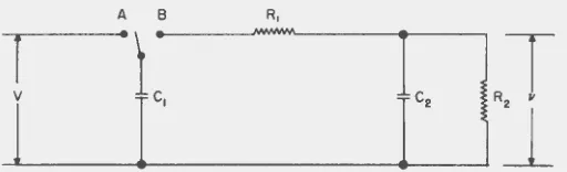
minimize all the factors that contribute to the pulse characteristics. For a known network a transient waveform may be evaluated by mathe-matical analysis. This analysis was made by Stone for the pulse
network shown in Fig. 1. This network, when the switch is moved
from A to
B,
results in an output voltage ofv
=
V
TlT2[e-t/T1- e
-t/T~'
(1)
RlC2 Tl - T2
:J
where
is the time constant of the decaying exponential, and
· T2 • 1/2
E
1 c 1 +R2c 1+R
2
c~
- l/2E
1 c 1 +R2 c 1+~c~
2 - 4R1R2c1 c2 (3)is the time constant of the rising exponential. If (1) is
differen-. tiated and set equal to zero, the time when v is maximum can be
determined as
t m
=
Tl - T2
If this value is substituted in (1), the maximum amplitude of the pulse is found to be
(4)
ISC-455
5
A B R,
•t
~
~vL_
______ ._c_,---~c-
2
---JR~
r
Fig. l - Basic pulse-forming network.
R2
.,
c,"2
El
V.VHN
··t
I
I1
r
R,
[image:8.599.198.454.314.392.2]The practical limits of choices of values for R1, R2 ,
c
1 andc
2 , as discussed by Stone, are determined by consideration of the ratio of the ma~imum pulse amplitude to the applied ch~rgfng volt~~e,the maxim~m repetition rates limited by time reqdired for resetting the network for subsequent pulses, and the time constants-of the
rising and decaying exponentials. Stone ~lso discusse~ -~pproximatioris
that can be made in choosing these values. It is the purpose-of this report to discuss in further detail the practical considerations
involved which will assure that the output pulse will meet the specifications demanded.
III. GENERAL DESCRIPTION
Fig. 3 shows the complete circuit diagram of the generator. Standard rack panel and chassis construction is used. The layout of the power supply, repetition rate generator and relay driving circuits is not critical. The current paths in the pulse~forming
network must be considered, however. This includes paths from the charging capacitor, through the relay contacts, through the series resistor, to the rise time constant switch and back to the charging capacitor
c
1 . Since the effect of inductance was not included in the transient analysis, leads in this region must be kept short. Since the terminating resistance may be a transmission line or an attenuator connected to the output, it is suggested that the ground connection of all components be made directly to the outside of the output connector with leads as short as possible.All power supply, repetition rate generator and relay driving circuit voltages are returned to a common bus which is not grounded. The polarity reversing switch then grounds either the negative or
positive side of the regulated 200-volt output to the voltage dividers and Helipot which supplies the charging voltage to
c
1 . A VR-tuberegulated voltage of 300 volts is supplied for the repetition ~ate
generator and relay driving circuits. This line is either 300 volts or 100 volts above ground, depending upon the position of the polarity reversing switch.
Fig. 4 shows the front panel. On the left is the main power switch, fuse and pilot light. The meter monitors the 200-volt supply for the divider and Helipot. Below the meter is the screwdriver
adjustment for this voltage. The meter is adjusted to read exactly full scale. Just to the left of this adjustment is a pair of
VOLTAGE DIVIDER PU~SE-FORMING NETWORK
RE:_A,· ·:0.: f.: C.• .f~'· :\Q,2
<360.411 COLO 224.0111 COL[' 165.7611COLO 53.50711 COLD • 52.00011
'\ ·-- ~~--..-~ w
.
-(+ 200 VOLTS--...
--4J7L~ -~M
.• _ (5WI
L
,.,2., 53...
.647~_
J
11.0000
2
COMMON NEGATIVE
r 4878.211 co~o
[MEMS~·r." ... : ~ 489t.On. WARM
LtCARRYING 20M
10 TURN NOMINAL 5K HELIPOT
0.1% LINEARITY
GROUND
_:~--_j~~-4~
1
L
-0.>01850
l
O.O'.l7707~01t:J
0.0318~1
,..d
T ,...r
,...
T
,...
Tc. . c. c. I~·
T1 • 0.1 T1 •O.Z T1 • 0.5 T1 ;, 1.0
,. sEc F•c I ,.uc 1 ,.uc
REPETITION RATE GENERATOR RELAY DRIVERS
- 4 3t1t' \'OL r~
-~-~=---~
r
i9~
~
.
.
;
·
{\
~~
I
-rn;~
~
.
~..
-::-:-- -::-:--
,.tdJ-r~
'":
lt2
1'
·
1'fd~
e~llfiiVING
T-
..
~ovl' JL:
'~...
.
COILf1£LAY
220K I ld IN ~ NOJ
.,,w
~CAT ~ ~6H6
IOK 20K COMMON NEGATIVE! . . • •
I - __ _.__,___ !NOT GROUNOEDI
IM
,.
5Z.OOOA
r
-
-
---+300
VOLTSII~ - - -- - -- -- - - -- - - -- ----
--~2:A
·
---
--
--
-
-
--~-- --· --- t-" -" - ,.. '""="" 125011 ""t'
·luH 20W
l
k> ' •~1
-
---
-
....
---I...J...A.._,III"
~
.lr' I I 65MAr
·
,i ·vR-150.ot,.ld - \j_',
22K ..
1-
J,.Id
IW
-
---
1
--
+200VOLTSlOOK WW l8ETW£EN Ill a
SOCMI
1+16,.1d •ZOO,.fd
~-800V li-600V
Fig.
3
VR -!50
+ zo,.r• IWWPIIlt.l
I I T • ·~~~ t45ov
CALtiiiAT R
(WW
I
IK ~ 1\oQ.T
:IWW -r> MONITORING
•
j
L
!
L
L
l
~~i
OUTPUT COMMONI NOT GROUNDED I NEGATIVE
PR£C.l
=.01,. . . 75K
••
Complete circuit of pulse generator.
[image:10.601.37.702.56.519.2]I
0
Cl.l
H
CX)
[image:11.601.39.753.56.579.2]ISC-455
9
coaxial output connector. Above the output connector is a switch for connecting an internal terminating resistance when the output is to be taken directly from the output connector to a high impedance load. In the upper right hand corner is the switch for selectlng
polarity of the output pulse. Left of·this switch is the Helipot-dial for setting the output pulse magnitude, variable from 0 to 50 volts.
The power supply is first regulated by VR-tubes at 300 volts, and is further regulated and controlled for the sourc~ to the
network with a 6Y6 series tube, a 6SJ7 ·control tube arid a -5651 voltage reference. Wire wound resistors and potentiometers are used to minimize drifts. Bleeders for the voltmeter and -the ·1 volt output are very carefully measured to within 0.1%. The ·meter-is calibrated with a shunting resistance until 200 volts on the output reads exactly full scale.
The regulated and monitored potential of 200 volts is ·fed through the reversing switch to a voltage divider consisting of series resistors and a 10-turn, 0.1% linearity Helipot, from which it is applied through the relay contacts to the pulse-forming net-work. Up to this point the voltage is monitored either on the meter or at the 1 volt output, and any changes which might occur due to drifts or changes in power supply component values can be detected and readjusted. Assuming a low enough repetition rate for·cl to recharge to within 0.1% each cycle, the voltage which is applied to the network is a function of the setting and linearity of the Helipot and the values of the series resistors and the resistance
-of the Helipot. The 0.1% linearity -of the Helipot is satisfactory, so that the problem is one of dividing the voltage so that the correct voltage necessary to give a 50-volt pulse from the network _is across the Helipot regardless of changing values of components in the
voltage divider.
When measured, the cold resistance of the particular nominal 5,000 ohm Helipot used in this generator was found to be 4878.2 ohms, and when measured after carrying 20 rna. for some time, this resistance was found to be 4891.0 ohms, a little over a 0.25% increase. In order tor the voltage across the Helipot to remain constant, it is
necessary for the series dropping resistance to change in the same direction by the same per cent. This was accomplished by combining wire wound power resistors having high positive temperaturecoefficients with precision wire wound resistors having negative temperature
coefficients until combinations were found to match the temperature characteristics of the Helipot.
The necessary voltage required across the Helipot for a 50-volt output pulse is slightly different for each rising exponential time ·
The repetition rate g~n~rator is a simple free runriing multi-vibrator with provision for raising the cathodes above cutoff for
turning off the rat~, and for providing single pulses. The output
of the multivibrator is integrated to give a slower rising w~vefor~
so that biasing the keying tubes will provide adjustment of relative delay times in operating the relays.
IV. SWITCHING RELAYS
Stone has offered considerable information on the behavior
of
the Western Electric 276 mercury relays. However, the non-polarized,
type 275 B Western Electric mercury relay was used in this pulse generator, mainly because this type was in stock and works quite well when driven in the cathode circuit of a pulsed vacuum tube. The static current of the tube in the non-pulsed condition serves as a biasing current, so that a relatively small signal is actually necessary to operate the relay.
The same type of pulse amplitude instability as noted by Stone
was observed. However, with the relay driven with a pulsed cathode
follower, the effect of changing repetition rates, varying residual current, or varying magnitude of the driving signal seemed to affect
this instability to a smaller degree. Instead, it seemed to deperid
more upon the voltage applied to the contacts and the impedance into·
which it was switched. For the network used in this pulse generator,
very few faulty pulses, due to the apparent effect of either arcing or vaporization of the mercury before actual closing of the relay contacts, were noted as long as the voltage was limited to values
below which a 50-volt output pulse was produced. For values higher
than this, the number of faulty pulses increased rapidly, until at
output magnitudes in the range of 75 to 100 volts, nearly every pulse
was faulty. At the lower voltages when a faulty pulse did occur,
it was easy to detect because the timing between the apparent closing of the relay and the arcing or vaporization of the mercury was small
enough so that a step could be readily observed on the pulse. Also
the magnitude of this step, which seemed to be nearly constant, was more apparent on a lower voltage pulse.
Another effect which could be more damaging than the occurrence of a few faulty pulses was a bridging of all the contacts in the
relay, or a sort of "make-before.lbreak" condition during the
switch-ing action. This of course left the impedance of the voltage source connected across the pulse-forming network during a part or all of
the pulse. Unless the voltage source impedance is constant and known,
or high enough during any magnitude setting to have negligible effect upon the pulse-forming characteristics of the network, this bridging
effect cannot be ignored. The regulated 200-volt source has a low
impedance to ground, so that it can be said the impedance looking back from the relay is the resistance from the Helipot arm back to the 200-volt line, in parallel with the part of the Helipot from the
arm to ground. Since this is also the impedance through which the
capacitor C1 must be charged between pulses, it must be limited if
ISC-455 11
when the Helipot arm is near ground, its effect upon the network would be controlling until after the "break" of the mercury
from the original contact. Bridging times were measured to be of
the order of several hundred microseconds (in no case lon~er th~n a
millisecond). Since a decay time constant of 100 microseconds was
chosen for this pulse generator, the bridging would persist during most of the pulse and Qertainly during the time when the maximum amplitude of the pulse is determined.
Initially an unsuccessful attempt was made to design some kind of a linearly controlled method of supplying voltage to C using ganged Helipots for keeping the resistance back through t5e source
constant for all settings of voltage. This might have been possible
if an accurately constructed control having the proper taper was
readily available, but no combination was discovered -using linear
controls whereby the output impedance could be corrected to be constant for all values of voltage.
The next attempt was to try a different type of network in-wnich
one could have a resistance in series with the supply large ·enough
so that the supply impedance could be neglected. The network-could
be arranged so that the capacitors in the network would be discharged by the relay contacts between pulses and the pulse formed by opening of the relay.
It can be shown that the network of Fig. 2 has nearly the same mathematical solution as the one in Fig. 1, starting with the node equations:
dv1 d(v1 - v2) vl - E
c2 + cl +
-
-
0dt dt R2
(6)
d(v2 - vl)
cl + v2
--
0.
dt R2
(7)
If Laplace transforms are applied to
(6)
and(7),
assuming as initialconditions at the opening of the switch, that t
=
O, and v1=
v2=
0,then the equations can be solved for the Laplace transform of v2 • When the inverse transform is taken, it is found that
- e
-t/T~
(8)This differs from
(1)
in that RJ is replaced by R2 . The ·equations for T1,
T2
and tm are exactly tne same as(2),
(3J and (4) respec-tively. The max1mum amplitude of the pulse is,
differing from (5) by the replacement of R1 by R2 .
However, the network in Fig. 2 has some faults which make it practically unusable. After the desired pulse has been produced, closing the relay to prepare the network for another pulse causes
(9)
a transient of opposite polarity at the output. This may be undesir-able unless some method is availundesir-able for eliminating its effect or discriminating against it while still allowing use of the desired pulse. In the network of Fig. 2, R is the terminating resistance, whereas in the network of Fig. 1,
t~e
terminating resistance is R2. R2 must be high enough in value so the variable impedance of the voltage source can be neglected. Then if R1 is to be a convenient low value of termination resistance, a high ratio of applied charging voltage to output pulse magnitude is required. From these consider-ations it was decided not to use the network of Fig. 2 as a solution to the relay bridging problem.The eventual solution was to isolate the voltage source before the start of the pulse by the use of another relay, and timing the relays so that the bridging effect was completed in the isolating relay before operation of the relay discharging
c
1 into the rest ofthe network. To prevent transients in the network after the pulse, C1 must be disconnected from the rest of the network before the voltage source is reconnected. This means that the isolating relay must open before, and close after, operation of the relay which forms the pulse. This is accomplished by partially integrating the gating pulse from the repetition gate generator, which slopes its front and back edges; then residual currents in the cathode followers driving the respective relays are adjusted so that the isolating relay operates at a lower level on the gating pulse than the pulse-forming relay.
V. PULSE-FORMING NETWORK
The design of the pulse-forming network was a combination of
compromises and reductions from the original specifications. Original-ly it was desired that the pulse have a decaying exponential time
constant of about a millisecond, maximum amplitude of 100 volts
ISC-455
13
requirements simple, it was decided that the ratio of voltage applied to the network and the maximum output pulse amplitude should not
exceed about 2 to 1.
For values of T2 (rising exponential time constant) that are very small with respect to T1 (decaying exponential time constant),
·the quantity
T1 - '1!2
in (5) is a factor close to unity, (For all {>OSitive values .of T1
and T2 it is
a
factor between unity and zero.) Then th~ ratio of applied voltage, V, to pulse magnitude, Vm, is approximately equal to R1C2/T2 • T2 is approximatelyc
1 times R1 and R2 in parallel, sothat ·
v
Rl + R2approximately equals • (10)
If this value is to .be less than 2, then R1 must not be larger than R2. T1 is approximately
c
1 times the sum of R1 and R , so to have a large enough value of T1 without an excessively higfi value for C1, R1 should be as large as possible, considering other limitations. For ·these reasons R1 was chosen equal to R2 , or 52 ohms.For a value of T1 equal to 1 millisecond the approximate value for
c
1 , with R1 and R2 fixed at 52 ohms each, would have to be about 10 microfarads. In order to obtain 100-volt maximum output with a 2 to 1 ratio of applied voltage to output p~lse magnitude, the min-imum .resistance of the Helipot, limited by its 5-watt .. rating and a slight safety factor, would be about 10,000 ohms. (It was later that the relay characteristics regarding faulty pulses at magnitudes higher than 50 volts was determined.) The maximum charging time constantoccurring with the Helipot arm at the midpoint, when there is no oth~
resistance in series to the regulated source, would then be 0.05 sec-onds. Allowing
7
time constants, for C1 to charge to within 0.1%, would establish a minimum charging period of 0.35 seconds, or amaximum repetition rate, assuming the charging time per cycle as half of the full cycle, of about
1.5
pulses per second. The specifica-tion for T1 was reduced to 100 microseconds, and a value of 1.0 microfarad was then chosen forc
1 •After the maximum pulse magnitude specification was reduced to 50 volts, the Helipot re~istance could be reduced to 5,000 ohms and dissipate only 2 watts, rather than the full rating of the Helipot. With approximately 5,000 ohms in series with the 5,000 ohm Helipot
volt maximum pulse amplitude, the maximum time constant occurs with the arm at the top of the Helipot, and is approximately 2.5 milli-seconds. The maximum repetition rate can then be about 30 cycles per second with a 7-time-constant charging period, especially if the
relay operating cycle is adjusted asymmetrically in the repetition rate generator to favor a slightly longer than half cycle charging
time. As the chosen pulse ~mplitude is lowered, the Helipot arm m~ves
toward ground, decreasing the charging time constant, allowing a ·
still higher rate without disturbing the accuracy of the generator.
After choosing values for R1 , R2 and c 1 according to the above considerations, it is now possible to find the exact values for c2
from (3) to give the exact desired values for T2 . For each value
of C2 determined for each desired T2, the ratio V/vm can be calculated
from (5). From this ratio the dropping resistance to the Helipot can
be determined.
The exact values of T1 can be calculated from (2). c1 was chosen by approximation on the basis of 50 ohm values for R1 and R2 . When actual values are used in (2), it is found that T1 proves to be higper
than the specified value by a~proximately T2 plus 4 microseconds
(Rl + R2 =52+ 52= 104 ohms).
In general a summary of the design limitations is as follows:
Repetition rate
Pulse magnitude
Output impedance
Rising exponential time constant
Maximum repetition rate is limited by mechanical operation of the relays to not much more than about 100 cps and by
the charging time constant. The charging
time constant is determined by the value of cl and the impedance of the voltage source.
For the network values used in this
generator, the pulse amplitude was limited to 50 volts maximum because of failure on the part of the relays. The maximum magnitude is also limited by the avail-able voltage source and the required ratio of the applied voltage to pulse magnitude.
Th~s is essentially determined by relative
sizes of R1 and R2 and the ratio of T1 to T2.
Terminating resistance R2 is chosen. Out-put capacitance c2 is determined by choice of T2 •
Decaying exponential time constant
Ratio of rising exponential time constant to decaying exponential time constant
ISC-455 15
T1 is approximately
c
1 times the sum ofR1 and R2 . Maximum value of
c
1 is limitedfor maximum repetition rates. R2 is-the
chosen value of termination resistance, and R1 is limited by its effect upon the ratio of necessary applied voltage to pulse magnitude.
If T1 equals T?, the algebraic sum of the
exponentials is zero, and no pulse can result. For T2 to be greater than T1, it is necessary tnat the radicals in (2J and
(3) be negative, so there can be no real
values of T1 and T2 with.T2/T1 greater than
unity. · ·
The theoretical values for
c
2 , T1 and V/vm for the particularvalues of T2 are as follows:
T2
c
microseconds microrarads
0.1 0.003850
0.2 0.007707
0.5 0.019324
1.0 0.038838
Tl microseconds 104.10 104.20 104.50 105.02 2.0154 2.0266 2.0621 2.1121
Fig. 5 shows the theoretical pulse-forms using these values in the pulse-forming network, assuming the Helipot setting for 50-volt amplitude.
VI. ATTENUATORS
The use of symmetrical attenuators is desirable so that a few attenuators can be combined to give any degree of attenuation without
requiring many separate units. One unit will terminate any other
unit, and the combination will still correctly terminate the pulse
generator. They can be used at ~ither end of a transmission line
whose impedance matches th~ input and output impedances of the
attenuators, and no care need be given to the direction of insertion. In order to further this convenience, non-polarized,
constant-impedance, quick-disconnect General Radio type-874 connectors are used on each end of the attenuators and at the pulse generator
out-put. General Radio provides adaptors from these connectors to
standard type N, C, BNC or UHF connectors, whichever type may be in
[image:18.601.51.582.44.711.2]l(\ l(\
..::;t
I
u rn
H
\.0
r l
"'
...
~
5 40
>
.!
30
20
10
0
{(;
&
v
i40 ~ T1 • 0.1 MICROSECOND
'tr
~
I-T1 • 0.2 MICROS[COND1"-r1 • 0.5 MICROSECOND
"':so 1--r. • 1.0 MICROSECOND
1\
~71
I
~20
\
II
1\ 10
I\
"'
T1 • 105.02 MICROSECOND)/
0
"'
0 I 2 3 4 !IT1•LOMICROSECOND TIME ttl- MICROSECONDS
i'-....
...
1---
r---0 50 100 150 200 2!10 300 350 400 450 500 550 600
TIME (I ) MICROSECONDS
Fig. 5- Calculated waveform of v showing trailing edgeforT2
=
1.0microsecond, and expanded plots of leading edges of
J;SC-455
binding-post, open terminals. Terminating resistance can be permanently mounted on these posts and the terminals be used as monitoring or connection points for high impedance loads.
17
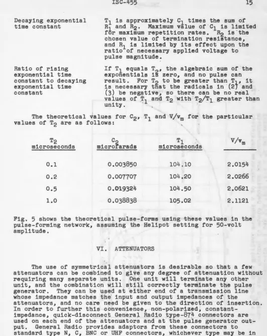
Either a tee or pi network could be used as the symmetrical
attenuator circuit. The tee results in a slightly simplified mechani-cal construction compared to the pi network unless a method is devised
for accurately making coaxial shunt resistance elements. Fig.
6
shows the values used in the tee for 10 to 1 and 100 to 1 voltage
attenuations. Fig. 7 shows the details of the attenuator units.
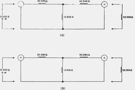
A more ideal unit would be a very short lossy section in a constant
impedance coaxial transmission line as shown in Fig.
8.
A sectionof the center conductor of the line would be made of a proper
resistive material and comprise the series elements of the attenuator,
and the shunting element would be a thin resistive disk to the oute~
conductor at the midpoint 'of the series elements. Thus any inductive
or capacitive effec~ would be distributed as part of the line's ·
characteristic impedance, and tend to eliminate error due to reactive
reflections at the attenuator. Commercially built 50-ohm' coaxial .,
attenuators are available. The tolerances of these units, however, are not nearly close enough for this application.
Fig.
9
is a photograph of the finished units detailed in Fig~·
7.
The units shown in Fig. 7 and Fig. 9 are the result of an effort to
keep discontinuities as small as possible, to distribute shunt ·
currents evenly to the outer conductor using small 1/2-watt carbon or deposited carbon resistors, and to produce a unit which, when finally assembled, could stand the usual amount of handling without transmitting variable stresses to the resistive elements or th.ir connections.
Deposited boron carbon resistors are recommended if available in the values and tolerances necessary for this application. However, if ordinary carbon resistors are used, their resistance will change
with heating, and a permanent change is. usually encountered even
after cooling. This means that all resistances have to be correct
after the soldering, process rather than before. Estimating t.he
amount of change which will occur during the soldering operation is not an easy task. A somewhat questionable method of arriving at the correct final values of resistance (although we used this method on this project) is to pick values somewhat low, solder the resistors in place and then, after all common connections have been made, apply heat in steps to the ends of resistors not common to
other resistors until the final value is th~ desired value. This is
a delicate and time consuming process, and if one resi~tor should
accidentally be overheated and have to be removed, it is possible that the heat necessary to loosen this resistor from the unit will cause other resistors previously adjusted by this method to again
change in value. The shunt element. of the attenuators is made of
several resistors in parallel and .arranged to point radially from
the .junction with the series elements. It is suggested that these
r
s2.ooo n
R IN
l
____
____
I
s2.ooon
R IN
L
10.505fi 52.0000
(A)
1.0401fi 52.0000
(B)
[image:21.601.35.498.255.566.2]BRASS END-PLATES
I •
I I
ISC-455
Fig.
7 -
Attenuator cross-section.COAXIAL TRANSMISSION LIN£
ATTENUATOR SECTION
1.591"
IRCUMFERENCE- 5")
Fig.
8 -
More nearly perfect coaxial tee attenuator. [image:22.601.75.520.194.381.2] [image:22.601.69.520.485.673.2]I
0 Cll
H
0
(\J
[image:23.599.56.757.59.582.2]ISC-455 21
Brass end-plates for the attenuator are machined from 3/8 inch
stock. The center hole is tapered to fit the rear shield of the GR ·
connector, the connector is disassembled, and the rear shield is per-manently soldered into the end-plate. The edges of the end-plates are drilled and tapped for screws which secure the thin brass sheet to be wrapped around the end-plates to form the outer cover after the
resistive unit has been assembled. The ends of the shunting
resis-tors project through holes in this sheet as it is wrapped and are soldered after the band is in place. The series resistor is soldered to the rear piece of the center conductor of the connector and
adjusted in value before the other components of the connector are
assembled. This prevents deforming the insulating spacer of the
connector by the heat of soldering and the resistance adjustment
process. The center connection of all the resistors is made first,
using resistors all slightly low in value. Then the free ends of
the series resistors are soldered to the center conductor rear pieces
and adjusted in value. The end-plates, with the rear shields in
place, are then slipped over the ends of the series resistors and
the connectors assembled. Then the brass sheet is wrapped around
the end-plates, the ends of the shunting resistors being pulled through holes in the sheet, and the sheet secured with screws into the end-plates. The ends of the shunting resistors are then soldered to the band and the value of the shunting resistance is adjusted by applying additional heat to each resistor end.
As mentioned before, the author is a little dubious about this process of resistance adjustment and would much prefer machining a unit as in Fig. 8 from good stable resistive material of high enough
resistivity so that a relatively small unit could be made. However,
the writer is not sure of the availability of such material. The development of resistors which exhibit purely resistive qualities at all frequencies and which will maintain exact values under all conditions of time, temperature and stress is an engineering problem
of concern to many. In equipment such as this pulse generator and
its attenuators the most important factor in securing accuracy is the availability of components furnishing ideal characteristics, rather than the computation of values to be put on the circuit diagram.
VII. ACKNOWLEDGMENTS
The author wishes to express appreciation to Dr. G. H. Miller, group leader in Experimental Physics for whom the work was performed,
for proof-reading this report. Also assistance and suggestions from
W. A. Rhinehart and from the members of the Electronics Shop of this Laboratory are sincerely appreciated.
VIII. REFERENCE
1.