HDC-2001
Hard Disk Controller
Technical Manual
~
ADVANCED
USA OFFICE
5432 PRODUCTION DRIVE HUNTINGTON BEACH, CA 92649
TELEPHONE : (714) 891-4004.
TELEX: 183210 ADVANCED HTBH
DIGITAL
CORPORATION
UNITED KINGDOM OFFICE
27 PRINCESS" STREET HANOVER SQUARE. LONDON W1 R8NQ
ADVANCED DIGITAL CORP. is proud to i ntt"'oduce its HOC-2001
HDC-2001 HARD DISK CONTROLLER Technical Manual
1. I NT RODUCT I ON ••••••••••••••
. .
.
.
.
.
.
.
.
. .
. .
.
. .
. . .
.
. . .
.
.
.
. . .
.
.
.
.
.
.
• Page 11. 1. General Descr i pt i Or'I.
.
.
.
.
.
...
.
.
. . .
.
.
• Page 1 1.2. Features •••••••. . .
.
. .
.
.
.
.
.
.
. .
.
.
.Page 21. 3. Speci ficat ions •• •• Page 3
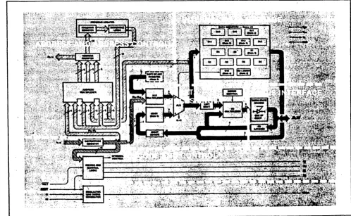
1. 4. Simplified System Block Diagram. • Page 4
2. I NTERFACE CONNECTORS." ••• " ••• "." ••••••••• " •• " ••••••••••••••••• Page 5
3. 4. 2. 1. 2.2. 2. 3. Organization •••••••••• Drive Control Signals •••• 2. 2. 1. RWC- ••••••••••• " 2. 2.2.
2. 2.3.
2. 2.4.
Write Gate- ••••• Seek Complete-. Track000- ••••• Write Fault-. H80-HS2-. Sector-. Index-. Ready- •• Step- •• Direction D81-0S4- •• In- ••
Control Driver/Receiver ••
.
.
• Page • Page •••• Page • Page • •••••••••••• Page •• Page .Page ••••••••• Page .Page ••••••• Page • ••• Page.
.
.
.
• Page • Page • Page •• Page 2. 2. 5.2. 2.6. 2. 2. 7. 2. 2. B. 2. 2. 9. 2. 2. 10.
2. 2. 11.
2.2.12. 2.2.13. 2. 2. 14.
2. 2. 15.
50 Pin Drive Control Connector.
34 Pin Drive Control Connector.
. . .
.
.
. . .
• Page Drive Data Signals •••2.3. 1. D1'''ive Selected- •• 2. 3.2.
2. 3. 3.
2. 3. 4. 2. 3. 5. 2. 3. 6. 2. 3. 7.
Timing Clock+. TimiY'lg Clock- •••
MFM Write Data +- ••••••••
MFM Read Data +- •••
Drive Data Connectors •••••••
Differential Data Driver/Receiver ••
.
....
• •• Page • •• Page • Page •• Page • Page • •• Page • Page •• Page • Page
INTERFACE TIMING ••••
.
.
.
.
.
.
.
. . .
.
. .
. .
.
.
.
. . .
.
. . .
. . .
.
. .
.
. . .
.
Page 3. 1. 3.2. TASK 4. 1. 4.2. 4. 3. D1'''i ve O1''''i veControl Timing. Data Timing •••••
. .
. . .
.
. .
. . .
• Page •• PageFILE •••••••• ~
.
. .
. .
. .
. .
.
. . .
.
. .
.
.
. .
.
.
.
. .
.
.
.
.
.
.
.
.
.
. . .
.
.
.
. .
.
.
PageTask Fi Ie Basics.
.
".
• Page Register Array •••. .
.
.
.
• Page Register Oefi Y'li t ions ••. .
. .
.
.
..
• Page4. 3. 1. Cc,mmand Reg ister ••
. ...
• Page4. 3.2. Statl.,s Register •• • Page
4. 3. 3. SOH Register •••••
.
.
.
•• Page4. 3. 4. Cylinder N'.lmber ••
. ....
• Page4. 3. 5. Sector N'.lMber ••
.
. .
.
.
• Page4. 3.6. Secto1''' Count ••
...
• Page4. 3. 7. Error Reg ister ••
...
.
.
• P4ilg eHDC-2001 HARD DISK CONTROLLER Technical Manual
4. 3. 8. Write Preccmlp •••
. .
.
.
• Page 154. 3. 9. Data Reg ister.
.
. . .
.
·
.
. · . . .
• Page 15 4.4. Stat I.'S Registers •• " •••· .
.
.
.
·
. .
• Page 16 4.5. status Registers Bits ••.
.
.
.
.
.
.. ·
.
.
··~age 16 4. 5. 1. El~r()t~ ••••••••...
.
. . . .
• •• Page 16 4. 5. .::. !;;;.. Corrected •••••.
.
.
.
.
.
·
..
• Page 16 4. 5. 3. Data Request ••·
. . . .
.
. . · ..
• Page 16 4. 5. 4. See~ Cornplete •• •• Page 16 4. 5. 5. Write Fault ••·
.
. · . .
. .
•• Page 16 4. 5. 6. Ready •••••••·
. .
·
.
• •• Page 17 4. 5. 7. Busy •••••••••. .
. .
.
.
. .
• Page 17 4. 6. E '1''' l'''CI 1''' Register Bits •• a • • • •...
• Page 174. 6. 1. DAM NClt Found.
·
. . .
• Page 17 4. 6 .-, • c:. TR000 Error •••••.
.
.
.
· .
.
.
.
.
•• Page 17 4.6. 3. Aborted Comnland.· .
.
• Page 17 4. 6. 4. ID Not F clurld ••· . .
.
. .
.
. . .
.
• Page 17 4. 6. 5. CRC El'''ror 10..
.
.
.
. . . . .
. .
• • Page 17 4. 6. 6. UnCClt"l'''ect a b 1 e....
• Page 18 4. 6. 7. Bad Block Detect •• • Page 185. . COMMANDS • • • • • • • • • • • • • • • • • II . . . Page 1 9
5. 1. Command Summary ••
.
. .
. . .
. . .
. .
.
• Page 20 5. 1. 1. Steppirlg Rates. • • Page 20 5. 1. 2. DMA Read..
. . .
.
. .
.
. . .
.
.
• Page c~0 5. 1. 3. Lorlg Read arid Write •• Page 21 5.2. Type I Cc,mmands.. . .
.
.
·
.
.
.
·
....
• Page 215.
.
~1. Restor'e • • Page 21
c:.
.
...
5. 0:> 1-. 2. Seek .••••
. . .
.
.
·
....
• Page 225. 3. Type I I C,:·rnmands •• • Page 22 5. 3. 1. Read Sect 1;)'1''''.
. . .
... ·
....
• Page .225 .. 3.2. Multiple Sectot" Reads •••
·
'..
Page 245. 4. Type I I I CI:lmma Y'ld s ••••• • Page 24 5. 4. 1. Write Sect I:;'''''' •• • Page 25 5. 4. 2. FClrmat T,,"'ack .•
·
....
· ...
• Page 256. PROGRAMMING.
.
. . .
.
.
.
.
.
. .
.
. .
.
.
.
. .
.
. .
. .
.
.
.
.
.
. . .
.
. · ...
Page 276. 1. Sett irlg Up Task Fi lese
.
. .
. . .
· ....
·
. . .
.
• • • • II • • Page 286. 1. 1. Cy 1 i rldet"s arId Track.s. • Page 28 6. ,---::0
.
Type I Comrl1arld Pl''''cigramm i ng ••·
....
...
.
.
.
· ....
• Page 286 . . ~
1. Steppi rig Rates •• •• Page 29
.::. • • • 110 •
6 •
.
:;.1;;;.. 2. Use elf B'Jsy Bit. • Page 29
6 •
.
I .••• :;. 3. Use of I nt e""l'''upt s •• •• Page 296. 2. 4. Use of the Err';)r Bi t •.
...
• Page 296. ... ~
L-:' • .:J. Use of the Cl::.rrected Bi t •• .Page 30
6.3. Type I I Commarld Prc,grammi ng •••
. . .
. . .
.
• Page 306. 3. 1. DMA MI:lde •••• Page 30
6. 3. 2. Block Moves ••
.
. . . .
Page 316. 3. 3. Usi rIg DMA ••• Page 31
6. 3. 4. Multiple Sectcll"" Tl""'ans fers. •• Page 31 6. 3. 5. Simulated Camp 1 £?t i e'YIS • • • Page 33 5.4. Type I I I CC'fIlmarld P""'I:rg,."amm i ng ••• •• Page 33
HDC-2001 HARD DISK CONTROLLER Technical Manual
7.
8.
b.5.
6.4.2. Intet"leavi rig •••••••••. Bad Bloc~. Mappirlg ...•••••••••• 6.5.1. Sector Pre-allocation ••
6.5.2. Alternate Tracks. 6.5.3. Spare Sectors.
6.5.4. Bad Block Bit.
THEORY OF OPE RAT ION ••••••••••• ' •••••••••••••••••
7. 1. 7.2. 7.3. 7.4. 7.5. 7. 6. General •••
Processor Functions.
7.2" 1. Fast 10 Select •• 7. 2. 2.
7. 2.3. 7. 2. 4. 7" 2. 5.
7. 2. 6.
7" 2. 7"
Serial 7. 3. 1. 7. 3. 2. 7. 3. 3.
7. 3. 4.
7. 3. 5. 7. 3. 6. 7. 3. 7.
Internal Bus Control. Reset Circuit •••••••• Processor Power Supply. Read and Write Ports •• Read/Write MeMory ••••
Miscellaneous Control Ports •• Oat a Separat ion •••.••••••
IncoMing Data Selection •• Reference Clock •••
CI,::.cK Gat ing .•••
High Frequenc~ Detector. Sample on Phase Detection •• Et"'t',::.t"' AMP 1 i f i et".
veo .•.
7.3.S. Window Extension . . 7. 3. 9. Cl.:.c~. Detect i.:.n •••. Data Conversion and Checking ..
7.4.1. AM Detect i c ' n . . . • •••. 7.4.2. Error Detection and Correction •.
7.4.3. Seri~l to Parallel Conversion. Sel'"' i aiDa t _~ Genel'"'a t ion . . . • . • . . . • .
7.5. 1. ~ilrallel to Serial Conversion. 7.5.2. CRC/ECC Generation ••
7~5.3. MFM Generation . . . Host Interface . . . . • .
7.6.1. Wait Enable.
7.6.2. 7. 6. 3. 7. 6. 4.
7. 6.5.
7.6.6.
Bus Gating .•
Register Selection . . . • • Interrupts and DRQs ••
Addl'''ess Select. Pl'"'C'M . . . •
MA I NTENANCE . . . .
8. 1.
8. 2.
8.3.
DRUN Adjustments . . . • • Oscillator Frequency. Balance Adjustment.
• Page Page • Page • Page • Page • • Page
Page
• • Page • •• Page • • Page · Page Page • Page • • Page • Page • • Page · • " Page • Page • Page • Page Page • Page • Page • Page · • Page Page · • Page • Page • Page • Page • Page ••• Page · Page • Page • •• Page • Page Page · • Page · Page • Page • Page
Page 34 35 35 36 36 36 38 38 38 39 39 40 40 40 40 41 42 42 43 43 43 44 44 44 45 46 46 46 47 48 49 49 50 50 52 52 53 53 53 53 54 55
• Page 56 • • Page 56 Page 57
A. DISK DRIVER EXAMPLE . • . . . . • • . . • • . . • • • • • • • • • • ~ ••••••.••••••••••. Page 59
A. 1. Polled Status Driver ••.
A.l.1. Initializatiorl.
. .'
..
B.
c;.
D.
E.
F.
-01 HARD DISK CONTROLLER Technical Manual
A. 1. 2. A. 1. 3. A. 1. 4.
Read Sector •• Write Sect.:.r ••
Task File Updating ••
. . .
. .
.
.
.
.
.
.
.
.
.
.
.
• •• Page • • Page 62 63 • Page 64INTERLEAVE CALCULATING UTILITY ••.
.
. .
.
.
.
. . . .
.
.
.
. .
. .
.
.
.
.
.
. .
. .
• Page 65B .. 1. BASIC Interleave Calculating Program.
. .
. .
.
. . .
.
.
. . . .
.
.
.
. .
Page 66SECTOR CALCULATING UTILITy •.•••••••
.
.
.
. .
.
.
.
.
.
. . .
.
. . .
.
. . .
.
Page 67C. 1. BASIC Sector"s per Track Ut iIi ty.
.
.
. .
.
.
.
.
.
.
.
. .
.
.
.
.
.
. .
.
.
.
• Page 68PROGRAMMERS QUICK REFERENCE •.•
.
.
.
.
. .
. . .
. .
.
.
. . .
.
. .
.
.
.
.
.
.
.
.
.
.
.
.
• Page 69D. 1. Task Fi 1 e •••••••
.
. . .
.
• •• Page 69D·:'
.
~. Val id Cc.mrnands •• • Page 69D.3. SDH Register Format.
.
.
.
. .
• •• Page 70D. 4. Status ay,d Err'or Register Bits.
.
....
• Page 70OPERATING SYSTEMS ••••••••••••••••• • Page 71 E. 1. Operating Systems Available. Page 71
DRAW I NGS . . . • . .
.
... .
Page 72F. 1. Schematic •••••••••••••••••••
.
..
• Page 72F. 1. 1. Microcontroller •••••• • •• Page 73
F. 1 .-, • c::. Bus Iy,te .. "'face/Dri ve Coy,trc.l ••
.
.
.
• Page 74 F. 1. 3. Data Separator •••••••••.
....
•••• Page 75F. 1.4. Se""'ial Data Iy,terface •• • •• Page 76 F. 1. 5. 8100 I Ylt er" face •••••••••
. . .
.
.
• •• Page 77G. APJ:tE"'DIX . . . • . . II . . . Page 78
G. 1. G.2. G.3.
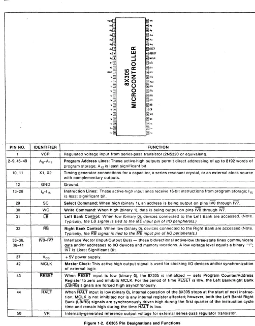
8X300 CPU.
ST506 •••.••
SA1000 or Q2000 Series ••
•• Page 78 • Page 79
HDC-2001 HARD DISK CONTROLLER Technical Manuel I~IBggY~I!gt::l
1. I N T ROD U C TID N
The HDC-2001 is an 8-100 bus Winchester Controller board with error correction (ECC) capabilities. It is designed to interface up to four Winchester disk irives. There are two versions of the board, the
HDC-1001-5/B. The HDC-2001-B can operate B" drive9. The HDC- 001-5 is used with
most 5-1/4" dt"ives.
The dr"ive signals are based upon the floppy look-alike interface available on the Shugart Associates' SA1000, the 8eagate Technology 8T506, and other compatible drives. All necessary buffers and receivers/drivers are included on the board to allow direct connection to the drive. Four 20 pin radial connectors are provided for data. Either a 34 pin (5-1/4" drive) or a 50 pirl (B" dt"ive) connector is provided for drive control.
All data to be written to or read from the disk, status information, and macro COMmands are transferred via the 8-100 bus. An on board sector buffer allows data transfers to the host computer independent of the actual data transfer rate of the drive.
HOC-2001 HARD DISK CONTROLLER Technical Manual
*
8-100 IEEE 696*
Single BV Supply*
Built-in Data Separator*
Built-in Write Precompensation logic*
Data rates up to 5 Mbits/sec * Control for up to 4 drives*
Control for up to B R/W heads*
1024 cylinder addressing range*
256- sector addressing range*
CRC generation/verification*
AutoMatic forMatting*
128, 256, or 512 bytes per sector (User selectable) * UnliMited sector interleave capability* Multiple sector reads and writes
*
Overlap seek capability*
Implied seek on all commands*
AutoMatic retries on all errors*
Automatic restore and re-seek on seek error*
Error correction on data field errors*
Diagnostic reads and writes for checking error correctionHDC-2001 HARD DISK CONTROLLER Technical Manual
Encoding method: Cylinders per Head: Sectors per Track: Heads:
01" i ve Se 1 ect s :
Step 1'''ate:
Data Transfer Rate: Write Precomp Time: eRC Polyrlomial: ECC Polyrlomial:
Reciprocal ECC Polynomial: Miscorrection Probability: Non-detection Probability:
CO ... l' .. ect i .::arl Sparl: Sect '::at" i rIg:
Host I Y'lt el'''f ace: Drive Capability: Drive Cable Length: Power Requirements:
Ambient Operating Temperature: Relative Humidity:
MTBF: MTTR: .
MFM
Up to 1024
Up to 256 (512 byte sec)
8
4
35 uS to 7.5 mS (0.5 mS increments) 4.34 Mbits/sec (SA1000)
5.000 Mbits/sec (ST506)
12 rlanoseconds X**16+X**12+X**5+1
X**32+X**28+X**26+X**19+X**17+X**10+ X**6+X**2+1
X**32+X**30+X**26+X**22+X**15+X**13+ X**6+X**:4+1
256 byte sector - (8.121 E-6 512 byte sector - <1.5 E-5
-2.3 E-10 5 bits
S.::.ft
8 Bit bi-directional Bus
1121 LS Loads
10 ft. (3 M) max.
+8V, ,3.IZIA Max (2.5A typ.) OCto 50 C (32 F to 122 F)
2121" t '::. 80"
HDC-2001 HARD DISK CONTROLLER Technical Manual S-100 BUS ,.!.J ... 0 S T I
,
Co-8.000 MHZ
r
O .,
"
IQ2)
CI'U.
D
,
~ coo.T1'IO\.
LATCH
•
~ OAT" LATCH
3
~ CAll. INTJIIQ. Wiil.
; f
r
O
""
10
I CONT~ 1 I
)-~
~ I ~ ~ SV~"01fT SlGN"LSCONTItQ4
I
I
SU""O"TINST,I'C)tI. ~ LOCiIC r-e-- CONTI'O\. SIClHAU
-,
I--t- Tt . . NQ ~""LS
WQt1r»01
11
l!tnAN"&' IUS. I
OI'IIVI CONTROl. , LATCH I
•
I
W011QG41 'NOllQ04l
t12111 W(WOAY 51"'''&''
SlCTO" "00f\l.SS .... ItALLlL
~ UlOIT
IU"."
~TlA ':01'1\1-
~~~lIU4.llL·
--
co .... 51"""" CIN .c"'ICK,III ICC'C1IC"'Oll'»-~ lIWOI'QG47
SIMPLIFIED SYSTEM BLOCK DIAGRAM - HDC- 001
!~!BQQy~!!g~ r---0
"
-" E C 0 ,.. T' ~"
l.---N011t»<11
r---~
O"T ..
S(Jt"""TOIIII .,
HDC-2~01 HHRU DISK CONTROLLER Technical Manual
2. I N T E R F ACE CON NEe TOR S
The HDC~001 has SiK on board connectors. These connectors consist of a two drive control connector, and four high speed data connectors.
The drive control cable is daisy-chained to each of the four drives. The dl'''ive
connected.
data connectors carry differential signals and are radially Up to four drives can be accommodated by the HDC- 001.
The Drive Control connector (J5 and J6) is a (relatively) low speed bus that is daisy chain connected to each of up to four drives in the system. To properly terminate each TTL level output signal from the HDC- 001, the last drive in the daisy chain should have a 220/330 ohm line termination resistor pack installed. All other drives should have no termination. Drive Control Signals are as follows:
2. 2. 1.
2.2.2.
2. 2. 3.
2. 2.4.
2. 2.5.
2.2.6.
RWC-Write
Bate-When the Reduce Write Current line is activated with Write Gate, a lower write current is used to compensate for greater bit packing density on the inner cylinders. The RWC- line is activated when the cylinder number is
greater than or equal to four times the contents of the Wt'i t e Pt~c(:.mp Reg i st et ....
This output signal allows dat~ to be written to the disk .•
Seek
Complete-Traek
000-Write
Fault-
HS0-HS2-I Y"lf·:.t'rtls the dt"ive has stabllized.
HDC-2001 that the head of the selected reached the desired cylinder and has Seek CC'fllplete is not checked a fter a SEEK command, thus allowing overlapped seeks.
Indicates that t"~ R/W heads are positioned on the ,:,utet'r.lost cyl iY"ldet~. This I iY"le is sampled imMediately
before each step. is issued.
Informs the HDC-2001 that ~1:lme faul t has occut~red on the sleeted drive. The HDC-2001 will not execute commands
HDC-2001 HARD DISK CONTROLLER Technical Manual
2.2.7.
2.2.
s.
2.2.9.
2.2. 10.
2. 2. 11.
2.2. 12.
Sector-
Index-
Ready-
9tep-For hard sectored drives, this line is used to indicate the sector boundries during formatting. Note that this line is not used unless special PROMs are installed to handle hard sectored drives.
Is used to indicate the index point for synchronization during formatting and as a time out mechanism for retries. This signal should pulse once each rotation
clf the disk.
Informs the HDC-2001 that the desired drive is selected and that its motor is up to speed. The HDC- 001 will not execute commands unless this line is true.
This I iY'.e is pulsed I::'Y',ce for each cyl inder 'to be stepped. The direction of the step will be determined by the Direction In- line. The step pulse period is determined by the internal stepping rate register during implied seek operations or explicitly during Seek and Restore commands. During auto restore, the step pulse period is determined by the Seek Complet~
time from the drive. Oi t"ect ion
In-
091-094-Determines the direction of motion of the R/W head when the step line is pulsed. A high on this line defines the direction as out and a low defines direction as in.
HDC-2001 HARD DISK CONTROLLER Technical Manual
2.2.13. Control Driver/Receiver
The c':'Y'lt,,""::al lines have the f,:.l·lowiYlg electrical specificatioYls:
Tt"'l_le= False=
HDC-2001 HARD DISK CONTROLLER Te~hni~al Manual
2.2.14. S0 Pin Drive Control Conne~tor
This Drive Control Connector (J5) is a 50 pin vertical header on tenth-inch centers that mates with Burndy *FRS50BS. The cable used should be flat ribbon cable or twisted pair with a length of less than 10 feet. The cable pin-outs are as follows:
+---~---+
Signal Ground Signal Pin I/O Signal Name
+---+---+---+-~---~---+
I 1 2 0
RWC-I 3 4 0 Head Select
2-5 6 NC
7 9 I Seek
Complete-9 10 NC
11 12 NC
13 1 4 0 Head Select
0-15 16 I
Sector-17 19 0 Head Select
1-19 20 I
Index-21 22 . I
Ready-23 24 NC
25 26 0 Dl'''ive Select
1-27 29 0 Dl'~i ve Select
2-29 30 0 Drive Select
3-31 32 0 Dl'~i ve Select
4-33 34 0
o
i t~ect i .;:.n1rl-35 36 0
Step-37 39 NC
39 40 0 Wt~ i t e
Gate-41 42 I
TR000-43 44 I Wl'~i te
Fault-45 46 NC
47 48 NC
49 50 NC
HDC-2001 HRRD
DISK CONTROLLER Technical Manual2.2.15. 34 Pin Drive Control Connector
This Drive Control connector (JG) is a 34 pin vertical header on tenth-inch centers that mates with Burndy #FRS34BS. The cable used should be flat ribbon cable or twisted pair with a length of less than 10 feet. The cable pin-outs are as follows:
+---+
I Signal Ground Signal Pin 1\0 Signal Name
+---+---+---+---+
1 2
a
IRWC-3 4 0 Head Select
2-5 6 0 Write
Gate-7 8 I Seek
Complete-9 10
11 12
13 14
15 16
17 18
19 20
21 22
23 24
25 26
27 28
29 30
31 32
I
I
0
I
a
II
a
a
0 0 0
TR000-Write Fault-Head Select
0-
Sector-Head Select
1- Index- Ready-
Step-Drive Select
1-Drive Select
2-Drive Select 3-Drive Select
4-33 34
0
DirectionIn-+---+---+---+---+
The Drive Data Connectors carry the high speed differential MFM data between the drive and the HDC-2001. Due to the loading characteristics of these differential lines, each of the drives have their own data connector. Drive Data Signals are as follows:
2.3.1. Drive
Selected-2.3.2.
This signal is not used on the HDC-1001. Timing Clock+
One half of the differential Timing Clock signal. This line contains a square wave signal equal to 1/64 the frequency of the write clock crystal.
2.3.3. Timing
Clock-This is the compliMentary version of Timing Clock+. 2.3.4. MFM Write
HDC-2001 HARD DISK CONTROLLER Technical Manual
2.3.5.
MFM
ReadData+-Differential MFM data froM the disk to the controller. 2.3.6. Drive Data Connectors
Four Data connectors (Jl~4) are provided for clock signals and data between the HDC-2001 and each drive. All lines associated with the transfer of data between the drive and the HDC~001 system are differential in nature and May not be Multiplexed. The Data connectors are 20 pin vertical headers on tenth-inch centers that mate with Burndy #FRS20BS. The cable used should be flat ribbon cable or twisted pair with a length of less than
10 feet. The cable pin-outs are as follows:
+---+---+---+---+
I Signal Ground I Signal Pin I 1/0 I Signal Name
+---+---+--~----+---+
2 1 I I Dr i ve Se 1 ect ed
4 3 I NC
5
8
11 12
15 16
5 7 9 10
13
14
17 18
I I I 0 I : 0
0 0
I I
Write Pl'''otect-NC
Timing Clock+ Timil"lg Cl':'ck-GND
GND
MFM Wl'"'ite Data+
MFfYl Wl'''ite
Data-GND
GND
MFM Read Data+
MFM Read
Data-19 GND
20 GND
.+---+---+---+---+
2.3.7. Differential Data Driver/Receiver
HIGH _ ... TRUe
AMD 26LS31
or
75110ANOTE: ANY AS 422
ORIVERJRECEIVER PAIR WILL INTERFACE
FLAT RIBBON OR TWISTED PAIR
MAX 10 FT.
">-_._
HIGHTRUE
HDC-2001 HARD DISK CONTROLLER Tachnical Manual
3.
I N T E R F ACE
TIM I N
a
+---
---+
SYMBOL CHARACTERISTIC MIN' MAX JNITS
+---
---+
twa Write gate pulse width 1 sector 2 rot3~lon
tDS Direction to step delay 250 nS
tSW Step pulse width 5 (typical' uS
tSP Programmed Step pulse period 0.01 7.5 uS
tSS Step to Seek Complete false 9 uS
tSC Last Step to seek Complete 128 Index
times
+---_._---+
Notes:
1. Write gate pulse width will vary depending on the sector size and the rotation rate of the disk.
2. Step pulse period will be equal to seek complete time during au. t"est.::.re.
-DRSE~HOSEL:x ______ ~ ______________ ~ _____________
x:::
- AWe
1/11/11;71111
VALID~)!IlI/I/UZ!lZllZZZZZlZIZI/I
-WRITE GATE
I
' - t W G - - - ' "
,
,
tDS-:
1
I
1
-- DIRECTION
1jj?!@liZiZi]
I 1 _ . _1 _ _
-~---~J
j~---tSP
.,
I ' t S W !
--STEP---,---~I ~I---~~~J
! tSS--' I
-I
- SEEK COMPLETE - - - -....
1 •
I
tSC - - - - 4
HDC-2001 HARD DISK
CONTROLLER
Technical Manual.
1~I~BE8g~ !l~l~§+---+
I SYMBOL CHARACTERISTIC MIN MAX UNITS I
+---+
tTC Timing clock period WCLK/16 (typical)I
tWD Write data pulse width 60 120 nS
tRD Read data pulse width 25 nS
+---+
+ TIMING
ClOC~
I
L
I i
: .... tTC-of
- TIMING
CLOC~
... _ ...+ MFM WRITE DATJ
I ~ tWO
- I I
-MFM WRITE D A T l _ _ I' .... _ _ I
+MFM READ DATJ
,
L
- MFM READ DATA
I
---,
I ~ I tRD
4. T ASK
F I L E
The HDC-2001 performs all disk functions through a set of registers ca.lled
the Task File. These register are loaded with parameters such as Secto~
Number, Cylinder Number, etc., prior to issuing a command. Individual t~egisters are selected via A0-2. The following registers are available.
+---+
I CS- I A2 I A1 I A0 I RE-
WE-+---+
I 1 I X I X I X I Deselected I Deselected I
o
0 1 0 I 0 Data Register Data Register Io
0 I 0 I 1 Error Register Write Precomp Io
0 I 1 I 0 Sector Count Sector Count Io 0 1 1 Sector Number Sector Number
o
1 0 0 Cylinder Low Cylinder Lowo
1 0 1 Cylinder High Cylinder Higho
1 1 0 Si%e/Drive/Head Size/Drive/Heado
1 1 1 Status Register Command Register+---+
4.3.1. Command Register
All commands are loaded into this register after the task reg'isters have been set. Writing to this register will cause the INTRQ Line to be reset. The COMmand register is a write-only register.
4.3.2. Status Register
4.3.3. SOH Register
After execution of a COMMand, the Status register is internally loaded with status information pertaining to the command executed. The host Must read this register to deterMine successful execution of the COMMand. The Status register is a read-only register; it cannot be written to by the host. If the busy bit is set, no other bits in this regist~r are valid. Accessing this register will cause the INTRQ line to be reset.
This register contains the ECC Mode, sector Size, Drive select, and Head select bits. The SDH.register is a
HDC-2001 HARD DISK CONTROLLER Technical Manual ·!8§~ E!bE
read/write register organized as ~ollows:
+---+
1 7 1 6 5 I 4 3 I 2 1 ·0
+---+
l E I Sec I Drive I Head I
1 Size 1 Select! Select
+---+
E=O eRC in data field E=l ECC in data field
+---+
+---+
Bit Bit Sector Size Bit Bit Drive Selected
6 5 4 3
+---~---+
+---+
o
o
1
o
1
1
256 Bytes
512 Bytes
12S Bytes
o
0 Drive Sel 1o 1 Drive Sel 2 1 0 Drive Sel 3
+---+
1 1 Dt"ive Sel 44.3.4.
4. 3. 5.
+---+
+---+
Bit Bit Bit Head Selected
2 1 0
+---+
0 0 0 Head 0
0 0 1 Head 1
0 1 0 Head 2
0 1 1 Head 3
1 0 0 Head 4
1 0 1 Head 5
1 1 0 Head 6
1 1 1 Head 7
+---+
Cylinder Number
These two read/write registers form the cylinder number where the head is to bL positioned on a Seek, Read, Write, or Format command. Internally, a separate set of cylinder register values are maintained for each drive. The two least significant bits of the Cylinder High register form the most significant bits of the cylinder number as illustrated below:
Registet" bits:
Cy I i rid et" bit s :
Sector number This Pl""' i Cit"
g~!inQ§r:
t:!iab
17J61514/3121110~I 1 1 1 19151
g~!ing§r: bQ~
17161514131211101 17161514131211101
4.3.6.
4.3.7.
4.3.8.
4.3.9.
Sector Count
register is a read/write register and may be read or written to by the host.
This read/write register is loaded with the number of sectors to be processed. On Read or Write multiple commands, the number of sectors to be transferred is loaded into this register. During a Fo~mat command, this register is loaded with the number of sectors to be formatted. During the course of a command, the Sector Count register is decremented towards zero and should be re-loaded for each command.
Error Register
This register contains specific fault information per-taining to the last command executed. This register is valid only if the Error bit in the Status register is set. The Error register is read only.
Write Precomp
The Write Precompensation register holds the cylinder number where the RWC line will be asserted and Write Precompensation logic is to be turned on. This wrlte-only register is loaded with the cylinder number divided-by-4 to achieve a range of 1024 cylinders. For example, i f write precompensation is desired for cylinder 128 (80 Hex) and higher, this register must be loaded with 32 (20 Hex). The Write Precompensation delay is fixed at 12 nanoseconds from nominal. On drives that require separate write precompensation anrl reduce write current cylinders, set the Write Precomp register to the cylinder where write current reduction
is desired.
Data Register
This register is the user's window to the on-board full sector buffer. It contains the next byte of data to be written to or read from the internal sector buffer. The Data register is accessed once for each byte in the sector. When the DRQ (Data ReQuest) line is asserted, the sector buffer contains data in a read command, or
is awaiting data to be written during a write command into the Data register. If the HDC- 001 is interfaced using programmed I/O, data transfers to this register can be implemented using block moves. This register may not be read from or written to except in the conte~" of a valid command.
HOC-2001 HARD DISK CONTROLLER Technical Manual I8§~ E!b~
There are two registers in the HDC-2001 that are used to Monitor the execution of commands. They are the Status register and the Error register. Each bit of these registers is used to define a particular type of status or error condition.
+--~---+
I Bit Status Register Error Register
+---+---+---~-~---+
I 7 , Busy I Bad Block Detect I
I 6 I Ready I Uncorre~table I
I 5 :' Write Fault I CRe Ert"or - IU Field I
I 4 I Seek Complete I 10 Not ~ound I
I 3 I Data Request I I
2 I Corrected I Aborted Command
1 I I TR000 Error
o
I Error I DAM Not Found+---~---+
4.5.1. Error
4. 5. 2. Corrected
4. 5. 3. Data Request
When set, indicates that a bit is set in the Error register. It provides an efficient means of checking for an error condition by the host. This bit is reset
on receipt of a new COMmand.
Indicates that there was a read error condition either in the data field or the ECC check bits themselves, and that the controller was able to correct the condition.
Functions almost identically to the hardware DRQ ~ine. When set, it indicates that the sector buffer is ready to accept data or contains data to be read out by the host. The Data Request bit is reset when the sector buffer has been fully read from or written to. Normally, the host need not consult this bit to determine i f a byte should be transferred.
4. 5. 4. Seek C':lmplete
4. 5. 5. Write Fault
Indicates the condition of the Seek Complete line on
the selected drive.
HDC-l001
HARD DISK CONTROLLER Technical Manual
4.5.6.
4.5.7.
Busyselected drive. The HDC-2001 will not execute any command if this bit is sat.
Indicates selected
the condition of th~ Ready drive. The HDC-2001 will not commands unless this bit is set.
line of execute
the any
After issuing a command, this bit will be set, indicating that the HDC-2001 is busy executing a command. No other bits or registers are valid when this bit is set.
4.6.1. DAM Not Found
4.6.2. TR000 Error
Will be set during a Read Sector command if, after successfully identifying the ID field, the Data Address mark was not detected within 16 bytes of ID field.
Will be set during a ,Restore command if, 1024 stepping pulses, the Track 000 asserted by the drive.
after issuing line was not
4.6.3. Aborted Command
4.6.4. ID Not Found
4.6.5. CRC Error ID
Indicates that a valid command has been received that cannot be executed, based on status information from the drive. For example, if a write sector command has been issued while the Write Fault line is set, the Aborted Command bit will be set. Interrogation of the Status and/or Error registers by the host can be
performed to determine the cause of failure.
When set, this bit indicates that an ID field containing a specified cylinder, head, sector number or sector size was not found.
HDC-2001 HARD DISK CONTROLLER T.ch~ical Manual I8§~
ElbE
4.6.6. Uncorractable
Indicates that an error was detected while reading the data field or ECC check bits and the error was so severe that the controller was not able to correct the condition.
4.6.7. Bad Block Detect
Indicates that a Bad Block Mark has been detected in the specified 10 field. If the command issued was a
write sector command, no writing will be performed. If generated from a read sector command, the data field will not be read. Note that bad block will not be detected if the flaw is in the 10 field unless Multiple
HDC-2001 HARD DISK CONTROLLER Technical Manual
3. COM MAN D S
The HDC-2001 executes five easy to use macro commands. Most commands feature automatic 'implied' seek, which means the host system need not tell the HDC-2001 where the R/W heads of each drive are or when to move them. The controller automatically performs all needed retries on all errors encountered including data field e~rors. If the data field contains an error, the controller will perform a correction, if possible. If the R/W
head mispositions, the HDC-2001 will automatically perform a restore and a re-seek. If the error is completely unrecoverable, the HDC-2001 will simulate a normal completion to simplify the host system's software.
Commands are executed by loading a command byte into the Command ~egister
HDC-2001 HARD DISK CONTROLLER Technical Manual
~~!~ ~gmm~ng EYmm~~~
For ease of discussion, commands are divided into three types which are summarized in the following table:
+---+
TYPE COMMAND 7 6
BITS
5 4 3 2
,
1
o
1+---+---+---+
I Restore 0 0 0 1 r3 r2 rl r01
1---+---+---+
, I· ' S e e k , 0 1 1 1 r3 t"2 r 1 r0 ,I---+---+---~---+
I II 1 Read Sector ' 0 0 1 0 D M L 0 I
1---+---+---+
I I I I 1 W,,"' i t e Sect or , 0 0 1 1 0 M L 0 I1---+---_
0_---+---+
1 III I Format Track I 0 1 0 1 0 0 0 0 I
+---+
L=Long Read/Write M=Multiple Sector
D=DMA Read Interrupt rX=Stepping Rate
5.1.1. Stepping Rates
+---+
r3-r0 - Stepping Rate 1
1---+---+
1 0000
=
35 uS 1 1000=
4.0 mS I1 0001 =0.5 mS ' 1 0 0 1 = 4.5 mS I
0010
=
1.0 mS ' 1 0 1 0=
5.0 mS 0011=
1.5 mS 1 1011=
5.5 mS 0100=
2.0 mS ' 1 1 0 0=
6.0 mS 0101 = 2.5 mS 1101=
6.5 mS 0110=
3.0 mS 1110=
7.0 mS 0111=
3.5 MS 1111=
7.5 mS+---+---+
5.1.2. DMA Read
Q - Q~8 B~2Q ~Qg§
o
= Programmed I/O Mode1 - DMA MClde
The DMA bit is used to position INTRQ in relation to DRQs during the read sector command. If the DMA bit is
HDC-2001 HARD DISK CONTROLLER Technical Manual
s.
1. 3. Long Read and WriteIf the Long bit is set, a special diagnostic read or write will be performed. During normal reads or writes, the ECC check bytes are not visible to the user. The Long bit allows the user to read and write these normally invisible bytes.
During a Read Long, the HDC-2001 will return a sector that is four bytes longer than the selected sector size. These four bytes will be the ECC check bits as recorded on the disk. During a Write Long, the host give the HDC-2001 a sector that is four bytes longer than normal. These four extra bytes are recorded in place 1:lf the ECC bytes that are nor"mally wt"itten aftel''' each sector.
The Read and Write Long option may only be used when the HDC-·2001 is in ECC mod9.
These commands simply positlon the R/W heads of the selected drive. Both
COMmands have expliCIt stepping rate fields. The lower four bits of these commands form the stepping rate which 15 stored for later Read, Write or
format operations.
5. 2. 1. Restore
The Restore command is used to calibrate the pcsition of the R/W head on each drive by stepping the head outward untll the TR000 line goes true. Upon receipt of the Restore command, the Busy bit in the Sta~us Register is set. Cy 1 i ndet.. High arid Cy 1 i rider" LI:JW l'''eg i st ers at"'e cleared. The lowet'
four bits of the command byte are stored in the stepping rate register for subsequent implied seeks. The state of Seek Complete, Ready and Wrlte Fault are sampled, and i f an error condition exists, the Aborted COMMand
bit in the Error register is set, the Error bit in the Status register is set, an intet""t"upt is gerler"'ated, arid the Busy bit is t""eset.
HDC-2001 H~RD DISK CONTROLLER Technical Manu.l
s.
2.2. SeekThe Seek command positions the R/W head to a certain cylinder. It is
pt"imari ly used to-~>start two or more coY'tc1Jrt"'ent seeks on drlves that support buffered stepping: Upon receipt of the Seek eommand, the Busy bit in the Status Register is set. The lower four bits of the command byte are stored in the stepping rate register for subsequent implied seeks. T~e state of Seek complete, Ready and Write Fault are sampled, and if an error condition exists, the Aborted command bit in the Error registe~ 1S set, the Error bit in the Status register is set, an interrupt i9 gene~atPd, and the Busy bit is ,,"eset.
If no errors are encountered thus far, the lnternal head position register for the selected drive is updated, the dlrection llre 1S set to the proper
direction and a step pulse is issued for each cyllnder to be stepped. When all stepping pulses have been lssued, the 9usy blt is reset and an
interrupt is Issued. Note that the Seek Complete line is not sampled after the Seek command, allowing multiple seek operatl0ns to be started using drives with buffered seek capability.
This type clf cClll1mand is chat"acterlzed by a tt'ansrer OT- a blOcK or data rt"(.Iht
the HDC-2001 buf~er t~ the host. ~hlS commana has an lmplicit stepping rate as se~ ~y the las~ Mestore or Seek ccmmanu.
5. 3. 1. Read Sector
The Read Sectct- r.:-':·:-1m~rld is used t,~ "r'ead a :;)ector of data ft"'om the disk to
the host C·:tfnOI.l1:e,"". UFt::'Y, ';"ece1Dl; of t.he Reao c!:::rMnano" the Busy bit in the
S-: at I.i= l''''eg 1 st e~- 1 s '~et. The s't at e c· f Seek Corro 1 e-r-: e, Ready and W""i t e F au 1 t ar"'e sampied, and l'f an et"t"'or cl:)ndltlon eXlsts. ;···,e Aborted CC,Imrnand bit In the Error reglster is set, the Error blt 1n tre Status register is set~ and a normal completion is slmulated.
Inlp 1 i ed Seek
If no errors are encountered so far, a Seek command is executed. The S~ek
Complete line is sampled. If the Seek Complete line does not go true
within 128 Index pulses, then the Aborted cOMmand bit in the Error register is set, the Error bit in the Status register is set. and a normal completion is simulated.
Retries
HDC-2001 HARD DISK CONTROLLER Technical Manual
not find an 10, if the 10 of that sector has a bad CRC, 1f the Data Address Mark (DAM) couldn't be found, or even i¥ the data was actually read from the disk but was in error.
El''''r''or COl'"'rect ion
If an error was detected while readinQ the data field, the controller will attempt to correct the error, If the error was correctable, ·the Corrected bit in the status register will be set and the command resumed. :f it was uncorrectable, the Uncorrectable Error bit will be set, the Error bit tn the Status register is set, and a normal completion is SImulated.
Every time the cl;:)Yltl'''ollel''' erlC=ounters 'an error, 1 t l'"'ecol'''ds the OCCUl'''l'''enC'e cof
that error in an internal register. If. after 16 retries~ the controllRr was not able to get a match on the ID field, It assumes that the head was possibly mis-positioned and executes an auto-restore. During the auto-restore, the stepping rate is lmplied to oe equal to the See~ Complete period. If the TRK000 does not go true withln 1024 steps, ehe TRK000 Err~r
bit in the Error register is set, the Error bi~ 1n the Status regIster is set and a normal completion is simulated.
After the auto-restore has been successfully comple~ed, the controller re-seeks and attempts to read the sector once again. An auto-restore wlll be performed only once per read or write sector ccmmand.
Hat"d Et"'l'"'()""s
If the controller encounters a non-recoverable error. the controller examines its internal error history register. It then sets the bit in tM~
HDC-2001 HARD DISK CONTROLLER Teehnieal Manual
Error Severity Levels
Although the HDC-~001 might encounter any number of errors in the course of executing a command, it only reports the most severe error. Errors ~re
ranked from most severe to least severe as follows.
1. Aborted Command
2. TR000 Error 3. Bad Block*
~ Uncorrectable
5. Data Address Mark Not Found 6. ID CRe Error
7. ID Not Found
*
Bad Block will only be detected if there is no ID CRC Error or ID Not Found Error in the sector with the Bad Block bit set.Normal Completion
If the HDC-2001 encountered no errors, it is considered a normal completion. The busy bit is reset. The status of the DMA bit in the command byte is examined. If this bit is reset (D=O; programmed I/O Mode) then an interrupt is issued at this time. DRQs are then generated for each byte to be read from the buffer. (Note: It is recommended that programmed I/O transfers should take place as a block move without consulting the DRQ bit in the Status Register.) After all the data has been moved from the buffer, the DMA bit in the command byte is consulted again. If this bit l S set (D=l; DMA mode) then an interrupt will be issued.
5.3.2. Multiple Sector Reads
If the M bit in the command byte is set, the~ th~ HDC-2001 WIll attempt to read multiple sectors. After all th~ data has been transferred from the sector buffer to the host on a read, tne Sector Number register is incremented, the Sector Count register is decremented, and if the Sector Count reaches zero or if a fatal error is encountgred, the HDC- 001 will stop and interrupt the host.
,
When a Correctable error is encountered during a multlple sector read, the occurance of the error is logged, but no interrupts are generated. After the whole multiple transfer is complete, the host can read the Corrected bit of the Status register to determine if any automatic corrections have taken place.
HDC-2001 HARD DISK CONTROLLER
TechnicAl Manual3. 4. 1. Write Sector
The Write Sector command is used to write a sector of data from the host computer to the disk. Upon receipt of the Write command, the controller generates DRQs for each byte to be written to the buffer. (Notel It is l'''ecommended that pl'''ogrammed 1/0 transfers should take place'.as a block move without consulting the DRQ bit in the Status register.)
After all data has been sent to the sector buffer, the Busy bit in the Status register is set. The state of Seek Complete, Ready and Write Fault are sampled, and if an error condition exists, the Aborted Command bit in the Error register is set, the Error bit in the Status register is set, an interrupt is generated and the Busy bit is reset.
Retries
Once the head has settled over the desired cylinder, it will attempt to read the 10 of the sector. The HOC-2001.performs all retries necessary to recover the Id during the write command. The controller attempts to read
the 10 of the desired sector up to 16 times. It will attempt a retry if it d~esn't find an 10 or if the ID of that sector has a bad CRe.
Aut.:;) Restore
Every tiMe the controller encounters an error, it records the occurrence of that error in an internal register. If, after 16 retries, the controller was not able to get a·match on the ID field, it assumes that the head was possibly mis-positioned and executes an auto-restore. During the auto-restore, the stepping rate is implied to be equal to the Seek Complete period. After the auto-restore has been successf~lly completed, the controller re-seeks and attempts to Write the sector once again.
If the controller encounters a non-recoverable error, the controller examines its internal error history register. It then sets the bit in the Error register of t~e highest severity error incurred. The Error bit in the Status register is set, an interrupt is generated and the Busy bit is \'''eset.
If the proper sector is located, the sector buffer is written to the disk,
an interrupt is generated and the Busy bit is reset~
cr • • • 2 . . Format Track
particular disk. Upon receipt of the Format command, the controller generates DRQs for each byte of the interleave t~ble to be written to the buffer. Information on settinq up an interleave table c~n be f~urd in Section 7. In all cases, the number 0"': t-f~e9 " rpil ... ~ .... erl'·l!!d tl-) t:,e ;_~I .. ffeY'
must correspond to the curY'ent sector size.
AfteY' all data has been set to the buffer, the Busy bl~ in t~~ Statue
l'''egister is set. The 48tate of Seek Complet~, Ready :: .. r~::l Wt"'i.i;~ F:u.;l'.: : :y,es are sampled. If an error condition exists, the AboY'ted Command bl~ ~ the Err,:,}''' register is set, the Error bit in the Status l"eqlster is S2t~ an
int~rrupt is generated and the Busy bit is rese~.
Implied Seek.
If no errors are encountered so far, a Seek command is executed. verification of track. positioning accuracy l S performed because the t
May not have any ID fields present. After the Seek oper~~ion has performed, the Seek. Complete line is samplec. If the Seek C~Mpl~t~
is not asserted within 128 Index pulses, the Aborted Command bit in Error register is set, the Error bit 1n ~~e Status register is set,
interrupt is generated and the Busy blt is reset.
\10 ck t:~erl , : ....
-t.he ~nOnce the head has settled over the deSIred cylinder, the controller walts urltil the Index line is asserted. Jrlee 1;he Index i~ f·"',uy,d • .:a Yllirniler r:lf TI')
fields and nulled data fields are wr1tten to the disk. The number of sectors written 1~ equal ~0 ~~e c~n~en~s of the Sector Cwun~ leqlst~r. ~~
-E'ach sectol"~ is wt"'ltten tl1e Sec'tl:'t"' C' ... ,nt .Reglstet"' !.s ~.ec:,rement~r"', ~",tj
:cnsequently, must be ~~ca1;ed before each format operation.
After the last sector l~ written, the con~roller back-fills the track With
4E's. When the next lndex pulse after the last sector 1S wrlt~en IS
encountered, the format operation is terminated, an i~t~rruct is gererated and the Busy bit is reset.
The FCIl'''rnat command fOt"rnats the track Hsing the f'Jllowir,g fc..t-'rnat:
, . . - - - ;:;EPEATEON TI~es
-,
7 .111
I
G:P GAP3 14 BYTES (At) loeNT CYl. SH SEC CRC 3B:B~TES • '2 ! .. ( RCi21b
BYTeS i ,IAt)
I
iF9' ,.,.-rA '"'A II !(.-e) (00) l.OW -2- (001; (00) Fl';LO ~ ·OO)!
t
I.e) jEC041 '
,
,.
,
"
.
I-; r
1,-___
10 FIELD _ _----'t
L-
OATAFIELO..-lH
200 nS. MIN. I.NOeX PUl.SeWRIT£ GAT£ - - - ' "
NOTE:
1) When MSa of SH t:7tte - 1. bad blOCk is
detected.
2) Write Gate tum-on is 3 bytes after the to fiekj's CRe t1tte.
3) Write Gate tum-otf Is 3 bytes after tna Data
Fl!kfs check bytM.
4) , 2 t1ttes of zeroes are re-written on a Data Field 26
5) The 2 LSS's Of the 'CE~n :~I!~ ;tf'" !J~;~ 'r;
:ylinder high.
These values are:
FE O!() 255
FF - 256 to 511
::'C -5~2 ~o i67
cD-'r;"', 'a "23
'-,-1ir'r!'!rs '=-(lIf'lCef'5
r:",.hnder.s
c-llir'lC'1en
,
---HDC-2001 HARD DISK CONTROLLER Technical Manual
6. PRO
a
RAM MIN BUsers familiar with floppy disk systems wIll find programming the HDC-2001 a pleasant surprise. A substantial amount of lntelligence that was required by the host computer has been incorporated Into the HDC-2001. The HDC- 001 pe,,"forn1s all needed retries, even on head posi t ionL-.g s,"rors. ~ f
there is an error in the data field~ the HDC-2001 will attempt to correct it. Most commands feature automatic 'implt~d' seek whi~h means that seek commands need not be issued to perform basic read/write functions. The HDC-2001 keeps track of the position of up to four reac/wY'lte head assemblies, so the host system does not have to maintain track tables. All transfers to and from the disk are through an on-board fulL sector cuffer. This means that data transfers are fully interruptable and can take place at a~y speed that is convenient to the system designer. In the event of an unrecoverable error~ the HDC~001 simulates a normal completion so that special el ... ';:)1' .. 1'''ecovery softwa,,"e is Y"IOt needed.
HDC-Z'001 HARD DISK CONTROLLER Technical Manual
Before any of the five commands may be executed, a set of parameter registers called the Task File must be set up. For most commands, this informs the HDC~001 of the exact location on the disk that the transfer should take place. For a normal read or write sector operatlon, the Sector Number, the Size/Drive/Head, Cylinder Number and Command register (usually in that order) will be written.
Note that most of these registers are readable as well as writable. registers normally are not read frOM, but this feature is provided error reporting routines can determine physically where an error without recalculating the sector, head and cylinder parameters.
These so that occu,,"red
Since the HDC-2001 can recall all the Task File parameters sent to It,' it is recommended that Task Fi Ie parameters be st.::.,,"ed in the HDC-.2001 as :they are calculated. This will save the programmer a few instructions and microseconds by not maintaining two copies of the same information.
6. 1. 1. Cylinders and Tracks
Since most hard disk drives contain more than one head per positioner, it is more efficient to step the R/W head assemblies of most disk drives by cylinders, not tracks. In other words, the disk driver software should be
design~d to read or write all data that is directly accessible by all the heads 'on a positioner before stepplng to a new cylinder. The following example illustrates a cylinder-by-cylinder sequential file read on a four head, two platter disk drive:
+---+
Physical L':lgical I PhyS tc.:ll I Physical
Cy I i rlde,.~ Head N llrn bel'"' He~ Side I Plat t e,," +---,--+. __
._---+----_ ... _ ... _---.... -_..:..:_---...
25 ! 3 T~p I B I
26 ' I 0 Bottom I A
26 1 Top I A
26 2 Bottom 8
26 ~ Top B
27 0 Bottom A
+---+
·Restore and Seek are Type I commands. These commands position the R/W heads of the selected drlve ane set the lmplied stepPing rate register. No dat a is t t"ansferl"ed t: c· Ol'" f"t'om the Pa.t a Reg i ster. T::. exeCI_lt e a Type I
command, the syste~ software m~gt d~ the following functions in this order:
HDC-2001 HARD DISK CONTROLLER Technical Manual
(HDC-2001 will attempt to execute Type I command)
2. Wait for interrupt or for Busy bit in Status Register to be reset
3. Check Error bit in Status Register for proper completion.
6. 2. 1. Stepping Rates
Most drives that use the HDC~001's 35 uS stepping rate require a slower rate (usually 3 mS or more) for Restore operations. This is why the
HDC-2001 allows you to have explicit stepping rates on both Restore and Seek. Upon power up, it is good practice to issue a Restore command with a slower stepping rate to recalibrate the head assembly. After waiting for that operation to COMplete, issue a Seek command with the faster stepping rate to set the stepping rate for subsequent implied seeks.
6. 2.2. Use of Busy bit
There are two different ways to sense the completion of a command. The first way, for smaller single user systems, is to poll the Busy bit of the Status Register. The Bus bit (bit 7) is set whenever the controller starts a disk operation and is reset whenever the controller is ready to communicate with the host COMputer.
The HDC-2001 busy bit is located in the same place a the sign bit of many computers to simplify the polling process.
This is one way to poll this bit using 8080 code:
WAIT:
6.2. 3.
IN ANA
JM
STATUS
A
'WAIT
Use of Interrupts
;Input HDC-2001, update sign flag ;Update 8080 sign flag
;Wait if busy (sign) bit set
Another more efficient way of notifying the CPU that the HDC~001 has completed a command is through interrupts. The INTRQ line on the HDC~001 makes a low to high transition whenever the disk controller requires CPU
intervention. This allows the host CPU to run other tasks while the HDC-2001 is reading or writing data to the disk.
6. 2. 4. Use of the Error bit
HDC-Z001 HARD DISK CONTROLLER
T.chnicAl ManualThis is one way to check the Error bit using 8080 code:
IN STATUS RAR
JC ERROR
;Get status <if not already in A) ;Rotate error bit into C
;Jump 1f error found
6.2.
s.
Use of the Corrected bitCorrectable errors are usually quite benign and can almost always be ignored. However, some systems designers may wish to log their occurence. The Corrected bit is positioned in the Status register to facilitate error l.::;.g,*ng. Cot"rectable and fatal el'''rors can be detected with the following 8080 code:
IN ANI
JNZ
STATUS
5
SOMERR
;Get HDC-2001 status
;Mask off Error and Correct bits ;Jump if we have either a correct-;able or fatal error
The Read Sector command is the only Type II command. This command is characterized by the transfer of a block of data from the HDC-2001 buffer to the host. This command features implied seek with an implicit stepping rate. To execute a Type II single sector command in programmed I/O mode, the system software must do the following functions in this order:
Note:
1.
2.
3.
4.
Set up Task File and issue command with OMA bit reset (HOC-2001 will attempt to read sector)
Wait for interrupt or for Busy bit in Status Register to be reset Do block move from HOC-2001 buffer to system memory
Check Error bit in Status Register for proper completion Steps 3 and 4 above can be reversed.
T.::;. execute i rlt et"t"'upt s,
a Type I I single or multiple sector command in DMA the system software does the following:
mode with
1. Set up Task File and issue command with DMA bit set
2. Set up OMA controller
(HDC-Z001 will attempt to t"ead single Cit" multiple sectors)
COMA controller will move data from HOC-2001 to memory) 3. Wait for interrupt from HOC-2001 ~
4. Check Error bit in Status register for proper completion
6. 3. 1.
The aboVe sequence is preferred but steps 1 and 2 above can be l''''evel'''sed.
DMA Mode
HDC-2001 HARD DISK CONTROLLER Technical Manual
the command byte that is used to optimize the HOC-2001's interrupts during prograMmed I/O and DMA operations. If the DMA bit is reset (0=0) the interrupt will come before the buffer is transferred. This ~llows a
programmed lID host to intervene and transfer ~he buffer of data. If the OMA bit ·is set (0=1) then the interrupt will happen only after the data has been transferred. This allows the host to go uninterrupted until the entire buffer has been transferred.
6.3.2. Block Moves
The HDC-2001 performs all transfers between it and the disk drive through an on-board full sector buffer. Once the disk has been read, the data is available to the host at any rate from DC to as high as a byte every 1.75
uS. In programmed 1/0 applications there is no nee~ to consult the DRG bit in the status register to determine if another byte is ready t~ be processed. Once an interrupt occurs or the busy bit is reset on a read, the host computer should do a block move of all the bytes in the se~tor.
The following 8080 code demonstrates a transfer from the HOC~001 to system memory. The transfer address is in HL and the byte count is in B:
READIT: IN
MOV
INX OCR
JNZ
DATA
M,A
H
B
READIT
;Get data from HOC-2001 sector buffer ;Store it in memory
;Increment memory pointer ;Decrement byte counter
;00 it again if whole sector not xfered The following Z-80 instruction does it all. The transfer address is in HL, byte count is in Band HDC-2001 data register address in C:
READIT: INIR ;Transfer buffer from HDC-2001 to memory
6.3.3. Using DMA
There are several features in the HDC-2001 which simplify the use of DMA.
Of course, there's the DRQ line that makes a low to high transition for each byte to be transferred. As mentioned earlier, there is a special bit in the Read Sector command which optimizes the HDC-2001 interrupts for DMA operation.
6.3.4. Multiple Sector Transfers