Abstract: This elaboration offers a dynamic model of an Active Magnetic Bearing (AMB) simulated in ANSYS Maxwell 17.1. This work reports simulation for two distinctive structure of AMBs that utilizations single electromagnets and double attraction type electromagnets put in 180 degrees separated from each other. At first, the theoretical model of single coil AMB and double coils AMB has been presented. It also deals with a simulation study of active magnetic bearings utilizing Finite Element Method (FEM) in two-dimensional (2-D) and three-dimensional (3-D) platform. 2-D and 3-D simulation have been compared for single and double coils AMB system. Magnetic properties such as- force, magnetic, flux pattern and flux density are performed and observed utilizing ANSYS Maxwell simulation software. This paper also includes a comparative study of an AMBs system with the variation in the gap between the actuator and the rotor and the effect of variation in inductance, flux, magnetic field and force are detected which is obligatory for hardware execution of an AMB system.
Keywords: Active magnetic bearing (AMB), Flux pattern, Ansys Maxwell, Electromagnetic Force, Finite Element Method (FEM).
I. INTRODUCTION
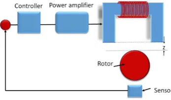
Active magnetic bearing (AMB) consists of two main parts: rotor and an actuator. The rotor is levitating in the air without any physical contact with the actuator by means of an actively controlled electromagnetic force. There are many benefits of an active magnetic bearing over conventional bearing such as contact-free, active vibration control and unbalance force compensation which can enhance the stability of the system [1,2]. As a result of low losses, frictionless and no mechanical wear, maintenance cost is diminished. The rotor can run at very high speed, the high circumferential speed is only restricted by the quality of the rotor material. It has been getting extended thought over traditional bearing in an industrial area because of the points of interest specified above. In rotor system applications AMB is extensively used, particularly where the conventional bearing comes up short. Different applications that utilized AMBs have been found in gas turbines, compressors, energy storage flywheel systems, machine tools blood pump and so on [2]. The basic components of an AMB system is illustrated in figure 1. AMB components consist of actuator, sensor, controller and rotor [3].
Revised Manuscript Received on September2, 2019.
Jonathan Laldingliana, EEE Department, National Institute of Technology Mizoram, Aizawl, Mizoram, India
Sukanta Debnath, EEE Department, National Institute of Technology Mizoram, Aizawl, Mizoram, India.
[image:1.595.322.496.178.279.2]Pabitra Kumar Biswas, EEE Department, National Institute of Technology Mizoram, Aizawl, Mizoram, India.
Fig. 1. Block diagram of Active Magnetic Bearing System.
Actuator: An actuator is the electromagnetic part which converts the controlled current into magnetic force. This force is the main source of energy to hovered the rotor in the air. The actuator of an AMB system can be different shapes and sizes and in this research work, the U-type actuator is considered [4].
A. Sensor: For levitating the rotor in the air constant monitoring of the rotor is essential. The sensors continuously monitor the spots of the suspending rotor and send the feedback to the controlling circuit. There are various types of sensor used for measuring the distance such as-ultrasonic sensor, IR sensor, capacitive type sensor, inductive type sensor and so on [5,7].
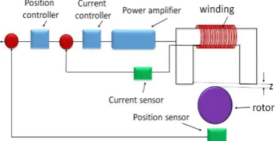
B. Controller: The signal feedback by the sensor should be carefully controlled for providing the correct amount of current required by the actuator. The proposed closed loop system of an AMB's is shown in figure 2. It has two controlled loops such as, inner current controlling loop and outer position controlling loop. Since the outer mechanical time constant is more than the inner electrical time constant loop, a response on the outer loop is expected to be slower than the inner current loop [5,6].
C. Rotor: The rotor, in standard constructions, is realized with a lamination packet shirked on a non-magnetic shaft. Tight manufacturing tolerances are needed in order to avoid unbalances. The mechanical properties of the rotor lamination have to be good, in order to overcome the centrifugal stress due to high speed rotation.
Fem Software Based 2-D and 3-D Construction
and Simulation of Single and Double Coils
Fem Software Based 2-D and 3-D Construction and Simulation of Single and Double Coils Active Magnetic
Bearing
Fig. 2. Proposed closed loop system of an AMB For designing a good AMB system it is important to investigated the magnetic properties of a system. In this research work, different types of magnetic properties are analyzed utilizing ANSYSMaxwell’s simulation software. U-type AMB is designed for single coil and for double coils placing the actuators at 180 degree as given in figure 3.
Fig. 3. Single and double coils AMB
II. THEORETICAL MODELS
Due to the flow of electric current, the magnetic field is generated in AMB [8]. According to Ampere’s Circuital Law, the relation between the current sum enclosed by the closed integration path and the magnetic field [9].
(1)
Where ‘I’ is the current through the coil and is the turn number.
Magnetic flux density is illustrated in equation 2.
(2)
Here, represents the iron core relative permeability and represents the air permeability ( ). The generated magnetic field depends on the material properties.
Assuming the magnetic flux in the actuator cross-section area is constant along the loop.
Additionally assuming
( ). Thus,
(3)
So,
The magnetic path is decomposed into two paths, the field in the magnetic material and in the air.
(4)
Where is the airgap between the actuator and the rotor and is the magnetic path length. From equations 2 and 4, and after solving for the relation gives the flux density in equation 5.
(5)
The magnetization on the iron can be neglected since the iron relative permeability
(6)
By considering the energy stored in the air gap, the AMB force is obtained as illustrated in equation 7.
(7)
The inductance of the electromagnetic circuit is given as-
(8)
Utilizing equations 3, 5 and 11 inductance equation is given by:
(9)
The main objective of an AMB is to produce an essential magnetic force to float the rotor situated in the bearing. The force produced by the electromagnet is the gradient of the magnetic field energy and depends on the air gap [10].
(10)
Where,
Here, is the magnetic field energy, is the magnetic force and is the air-gap volume. The attractive force between the magnet and the ferromagnetic material is non-linear. Therefore, at any instant of time, the attractive force between the rotor and the actuator is-
(11)
With equations 9 and 11, equation 12 can be derived:
(12)
[image:2.595.64.221.244.357.2]For a pair of actuators, the force denotes the difference in force between the negative and positive directions. In this case, the actuator currents are defined as the difference of a bias current and a control current for the negative actuator, and the sum of a bias current and a control current for the positive actuator. The air gaps are defined by the deviation and the nominal air gap . Therefore, the relations and are introduced.
(13)
Here, is the angle between the center of the cross section and the force direction and is the force constant.
II. FINITE ELEMENT METHOD
FEM is a numerical method for cracking problems of engineering and mathematical physics. Typical problem areas of attention consist of fluid-structure interaction, thermo-chemo-mechanical problems, biomechanics, thermochemical and electromagnetics [12]. Maximum of these techniques are defined by means of Partial Differential Equations (PDEs). However, for a mainframe to explain these PDEs, numerical techniques have been established over the last few ages and one of the outstanding ones is the Finite Element Analysis (FEA). It is utilized as the root for current simulation software and benefits researchers and engineers to spots the weak point, the strength of the force, etc. in their plans. The outcomes of a simulation based on the FEA method are frequently represented via a colour scale that shows, for example, the direction of the force of an electromagnet. For making a simulation, a mesh, comprising of thousands of small elements that together form the shape of the structure desires to be finished. Calculations are obtained for all elements. Joining the separate outcomes gives us the concluding result of the structure [13].
In this work, Ansys Maxwell 7.1 has been utilized for electromagnetic analysis of a single and double coils Active Magnetic bearing [14,15]. ANSYS Maxwell is the industry-foremost electromagnetic field simulation software for the analysis and design of actuators, motors, sensors, coils, machines, transformers and other electromagnetic devices. With Ansys Maxwell, the characteristic of the nonlinear system, the transient motion of electromechanical apparatuses and their control system design and effects on the drive circuit can be summarized. This simulated electromagnetic laboratory gives the user an important competitive benefit with quicker time to market, reduced costs and better system performance.
Utilizing the following Maxwell equations, the static magnetic field can be defined-
(14)
Where, is the divergence operation, is the free charge volume density and is electric displacement field. Assuming the medium is linear, isotropic, and homogeneous
(15)
Where, is the electric field and is the permittivity of the medium. Putting the above equation into Gauss’s Law we have the constitutive equation-
(16)
According to Faraday’s law
In the absence of a changing magnetic field
(17)
However, the curl of electric field ( ) is zero, electric field can be illustrated as-
(18)
Where: is the electric potential. Therefore, using the above equations Poisson’s equation for electrostatic can be obtained [11].
(19)
Also, Poisson’s equation for magneto static field is expressed in equation 20
(20)
Where, is the source current density.
Equation 20 is suitable for calculating the magnetic field in magneto-static. Magnetic field will be used further for calculating the magnetic force of an AMB system.
Fem Software Based 2-D and 3-D Construction and Simulation of Single and Double Coils Active Magnetic
Bearing
Fig. 4. Basic Diagram of U-type AMB
III. CONSTRUCTION OF AMB USING ANSYSMAXWELL
[image:4.595.353.496.52.214.2]Ansys Maxwell 17.1 is one of the ideal work-bench for analysing and designing of AMB system. Flow chart for designing an AMB is given in figure 5 and the designing procedure of an AMB is discussed below.
Fig. 5. Flow chart of AMB system design
A. Construction of an AMB using 2-d ANSYS Maxwell. Project is created utilizing Maxwell 2-D design and project name is given for a particular designed.
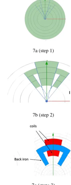
[image:4.595.84.200.61.180.2] Model: Is this section, model is created separately for a rotor and the actuator. Creating two circles and subtracting the inner circle using Boolean subtracting from the editing toolbox rotor is created which is represented in figure 6. After the rotor is created actuator is created by drawing multiple circles and line the unwanted areas are subtracted using Boolean subtraction and the colour properties are changed. Red colour indicates the coils of the actuator and blue colour is the back iron which is demonstrated in figure 7.
Figure 6: Construction of 2-D rotor of an AMB
7a (step 1)
7b (step 2)
7c (steps 3)
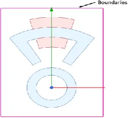
Fig. 7. Construction of 2-D actuator of an AMB Material properties and boundaries: The
[image:4.595.340.482.264.630.2]Vector potential boundaries is created and the percentage overshoot selected is 10% which is given in figure 8.
Figure 8: Overall model of single coil AMB in 2-D form
Excitation: In Ansys Maxwell 2-D design there are three type of excitation. In this designed, current density
is selected.
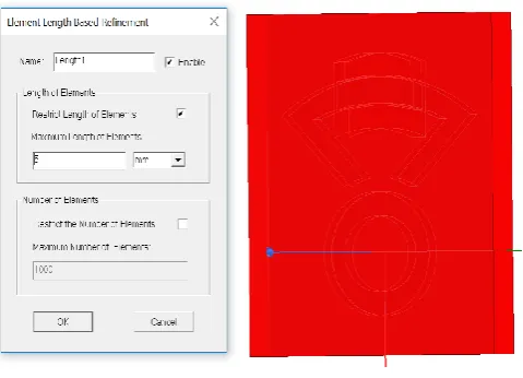
Mesh operation: Mesh cells are utilized as discrete local approximations of the larger area. The type of mesh used is length-based meshing with a maximum length of elements=5mm, region= inside a selection, the maximum number of elements=1000 and restrict length=true.
Parameter: There are three types of parameters in a 2-D design such as- force, torque and matrix. In this design, the force parameter is applied in the rotor object and global is selected in the coordinate system as illustrated in figure 9.
Fig.9. Force assigned to the rotor
Analysis: From the project tree by clicking the analysis the Solve Setup window appears which is represented in figure 10. When the software produces a result, it clearly calculates the field values at each node in the finite element mesh and interpolates the values at all other points in the problem section. On the General Tab, the Maximum number of passes is set at 10 and percentage refinement per pass is set at 1% which tells the software what target error to accomplish within the number of passes permitted. By clicking the Convergence Tab, refinement per pass is set to 30% which instructed the computer to increase the number of mesh triangles by up to 30% after each adaptive solution. A minimum number of passes is
[image:5.595.86.217.103.223.2]set to 2 to force the solver to solved at least two passes and the minimum convergence passes is set to 1. On the Solver tab the nonlinear residual field is set to 0.0001, this unit specifies how close each result must come to satisfying the equations that are utilized to calculate the magnetic field.
Fig.10. Solve Setup windows.
2-coils AMB setup: A single coil AMB is duplicated along the round axis with an angle of 180 degree utilizing the editing tree as given in the figure 11. By clicking on the object in the modeler the new coil is selected and current density excitation dialog appears. Therefore, the value of the current density is input in the current density excitation tab and the 2-D designed is ready to analyzed.
[image:5.595.73.214.453.562.2] [image:5.595.326.543.493.707.2]Fem Software Based 2-D and 3-D Construction and Simulation of Single and Double Coils Active Magnetic
Bearing
B. Construction of an AMB using 3-D Ansys Maxwell. In this section, new project is created using Ansys Maxwell 3-D design [14]. Steps of construction is similar with 2-D designed as shown in the flowchart above (figure 5).
Rotor and actuator modelling: Rotor is designed by creating two cylinders with radius of 40mm and 25mm, both have the same thickness of 17mm. The inner cylinder is subtracted from the outer cylinder with the help of Boolean subtraction as represented in figure 12.
Fig.12. Design of 3-D rotor
Actuator back iron is created by drawing a multiple line from the drawing tool box, all the lines are selected and grouped together using Boolean unite tool from the editing tool box. The line is converted into a sheet by clicking the surface-coverlines in the modeler. A line of 17mm is drawn along the z-axis and along this direction a sheet is swapping which gives the thickness of the actuator’s back iron which is displayed in figure 13
Fig.13. Back iron design
Actuator coil is drawn from the drawing toolbox and is converted into sheet using
modeler surface-coverline. 2-D sheet is converted into 3-D object by swapping along z-axis with a thickness of 25mm. Applying Boolean subtraction coil is subtracted from the back iron in order to make a hole in the coil which is illustrated in figure 14.
Fig.14. Coil design of the actuator.
Combining the rotor, coil and the back iron, a single coil -AMB is formed which is represented in figure 15. 2-coils AMB is created by duplicating the actuator along the axis with an angle of 180 degree (figure 16).
Fig.15. 3-D model of single coil AMB.
Fig.16. 3-D model of double coils AMB.
Fig.17. 3-D coil design
[image:7.595.346.515.355.492.2] Parameter and Meshing: From the Maxwell 3-D tree, Lorentz force is assigned in the rotor and meshing is done by selecting all the objects and the maximum length of elements assigned is 5mm.
[image:7.595.49.289.375.548.2]Fig.18. assigned force to the rotor
Fig.19. Meshing widows
Analysis: Similar to the 2-D solution setup, 3-D analysis setup is formed and the 3-D designed is ready to analyze.
IV. RESULTS AND DISCUSSION:
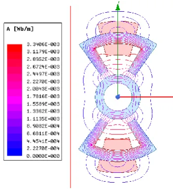
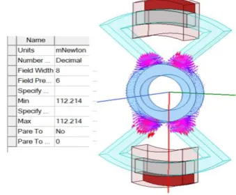
2-dimension and 3-dimension FEM simulation has been implemented to determine the flux pattern, force, magnetic field and flux density for single and double coils AMB. The number of coil turns is 500 and coil current is 4A. Figure 20 to figure 27 shows the flux pattern, flux density, magnetic field and force for 2-D single and double coils AMB with an air-gap of 10mm for a single coil AMB. The magnetic properties of 3-D single and double coils AMB are provided in figure 28 to figure 31. From this simulation result, the flux pattern and direction of force is visible. In case of 3-D model all the magnetic properties such as- flux density, field intensity and direction of force can be visualized in all the
dimensions while in 2-D model magnetic properties can be imagined in two dimensions. Comparing the flux density, field intensity and force for 2-D and 3-D designed, the values are very much closed but slightly different. Relating the force between single and double coils AMB in both 2-D and 3-D (figure22, figure27, figure30 and figure31), the force experience by the rotor is much superior in single coil AMB then force in double coils AMB. This is due to the fact that in single coil AMB the pull-up force produced by the actuator is very much higher than the pull-down force (gravitational force), whereas in case of double coils AMB the two actuator are positioned facing each other, as a results the pull-up force and pull-down force are alike and cancelled out at the center of the rotor. Due to this cancellation, the force experienced by the rotor is very closed to zero in both 2-D and 3-D designed. Simulation has been carried out for three different airgaps (10mm, 15mm and 20mm). With the variation of air-gap the inductance (figure 31) of an AMB system deviates rapidly thereby changes the transfer-function of an AMB system at different operating points for both single and double coils AMB. It is observed that the flux, flux density and magnetic field reduced with the enlarged in air gap between the actuator and the rotor. With the reduced in magnetic field the attractive force between the rotor and the actuator reduced as illustrated in figure36.
Fig. 20. Flux pattern of 2-D single coil AMB (airgap=10mm)
[image:7.595.338.515.540.697.2]Fem Software Based 2-D and 3-D Construction and Simulation of Single and Double Coils Active Magnetic
Bearing
[image:8.595.351.503.58.228.2]Fig. 22. force of 2-D single coil AMB (airgap=10mm)
Fig. 23. Field intensity of 2-D single coil AMB (airgap=10mm)
[image:8.595.87.244.228.361.2]Fig. 24. Flux pattern of 2-D double coils AMB (airgap=10mm)
[image:8.595.340.514.284.487.2]Fig. 25. Flux density of 2-D single coil AMB (airgap=10mm)
Fig. 26. Field intensity of 2-D single coil AMB (airgap=10mm)
[image:8.595.77.253.415.609.2] [image:8.595.339.516.540.713.2]Fig. 28. Flux density of 3-D single coil AMB (airgap=10mm)
Fig. 29. Field intensity of 3-D single coil AMB (airgap=10mm)
[image:9.595.78.256.256.403.2]Fig.30. Magnetic force of 3-D single coil AMB (airgap=10mm)
[image:9.595.343.509.296.503.2]Fig. 31. Flux density of 3-D double coils AMB (airgap=10mm)
Fig.32. Magnetic field of 3-D double coils AMB (airgap=10mm)
[image:9.595.74.258.474.624.2] [image:9.595.341.511.559.699.2]Fem Software Based 2-D and 3-D Construction and Simulation of Single and Double Coils Active Magnetic
Bearing
[image:10.595.61.277.196.313.2]Fig.32. Inductance Vs airgap (10mm,15mm and 20mm)
[image:10.595.55.278.349.480.2]Fig.33. Flux Vs airgap (10mm,15mm and 20mm)
[image:10.595.54.278.498.747.2]Fig. 34. Flux density Vs airgap (10mm,15mm and 20mm)
Fig.35. Magnetic field Vs airgap (10mm,15mm and 20mm)
Fig.36. Force Vs airgap (10mm,15mm and 20mm)
V. CONCLUSION:
In the present scenario, the hypothetical model of single-coil and double-coil AMB has been exhibited. A well-ordered construction of 2-D and 3-D model of a single and a double-coil AMB has been displayed. A two dimensional and three-dimension FEM analysis has been carried out utilizing ANSYS Maxwell 17.1 simulation software. A similar investigation of single-coil and double-coil AMB has been introduced in this paper. It is discovered that the force experienced at the center of the rotor is higher in single-coil AMB as compared to double coil AMB because, in case of double coil AMB, the force generated by both the coils are propped each other at the center of the rotor which results in minimizing the force at the center of the rotor, while in case of single coil the force generated is only countered by the gravitational pull due to this the force experience at the center of rotor is high as compare to double coils AMB. Magnetic analysis has been performed for three different airgaps for single and double coils AMB, it has been found that in both the models, with the increased in air-gap between the actuator and the rotor magnetic properties such as- flux, flux density, magnetic field and force continue diminishing. In order to have a constant magnetic property for different air-gaps, the actuator current density should be increased with the increase in air-gap.
ACKNOWLEDGMENT
The authors of this paper wish to show gratitude to Science and Engineering Research Board (SERB), DST, Government of India for financially supporting the project.
REFERENCES
1. L. Papini, L. Tarisciotti, A. Costabeber, C. Gerada, P. Wheeler,"Active Magnetic Bearing system design featuring a Predictive current control," IECON 2016-42nd Annual Conference of the IEEE Industrial
Electronics Society. IEEE, 2016.pp. 3217-3222
2. B. Singh and V. Kumar, “A real time application of model reference adaptive PID controller for magnetic levitation system,” Power, Communication and Information Technology Conference (PCITC), 2015 IEEE, 2015, pp. 583–588.
3. P. Raghunathan and E. Logashanmugam, “Design and testing of electro-
magnetic actuator used in axial active magnetic bearing,” International Conference on Control, Instrumentation, Communication and Computa- tional Technologies (ICCICCT), 16-17 Dec. 2016, Kumaracoil, India. IEEE, July2017.
4. D.D. Quinn, G. Mani, M.E. Kasarda, T. Bash, D.J. Inman and R.G.
Kirk, "Damage detection of a rotating cracked shaft using an active magnetic bearing as a force actuator-analysis and experimental verification." IEEE/ASME transactions on mechatronics 10.6 (2005). pp. 640-647.
5. S.E. Mushi, Z. Lin and P.E. Allaire. "Design, construction, and modeling of a flexible rotor active magnetic bearing test rig." IEEE/ASME transactions on mechatronics 17.6 (2011), pp.1170-1182. 6. J.D. Lindlau, C.R. Knospe, "Feedback linearization of an active
magnetic bearing with voltage control." IEEE Transactions on control systems technology 10.1, 2002, pp. 21-31.
7. S. Zhou and J. Shi. "Active balancing and vibration control of rotating machinery: a survey." Shock and Vibration Digest 33.5 (2001), pp. 361-371.
8. S.E. Mushi, Z. Lin and P.E. Allaire. "Design, construction, and modeling of a flexible rotor active magnetic bearing test rig." IEEE/ASME transactions on mechatronics 17.6 (2011), pp. 1170-1182.
9. D. Meeker, "Example: Radial Magnetic Bearing (Nonlinear Magneto
static,)." (1999).
10. J.P.A. Bastos and N. Sadowski, “Electromagnetic modeling by finite
element methods”. CRC press, 2003.
11. R.H. Kingston, and S. F. Neustadter.
electric field, and free carrier concentration at the surface of a semiconductor." Journal of Applied Physics 26.6 (1955): 718-720.
12. O.C. Zienkiewicz, R.L. Taylor, P. Nithiarasu and J.H. Zhu, “The finite
element method”. Vol. 3. London: McGraw-hill, 1977.
13. T.J. Hughes, “The finite element method: linear static and dynamic
finite element analysis”. Courier Corporation, 2012.
14. ANSYS Inc., Licensing Guide, Release 12.1 (002829), November
2009.
15. Introduction to Scripting in Maxwell, ANSYS 2017.1.
AUTHORSPROFILE
Jonathan Laldingliana was born in Mizoram, India in the year 1989. He completed B.Tech. degree from North Eastern Regional Institute of Science and Technology (NERIST) in 2012 and crack a Graduate Aptitude Test in Engineering (GATE) in the year 2012. He pursues M.Tech from Visvesvaraya National Institute of Technology (VNIT Nagpur) and got a degree in the year 2014. He is a former guest faculty in Mizoram University (2014 to 2016) and he is presently a fulltime PhD scholar at National Institute of Technology, Mizoram, India.
Sukanta Debnath was born in Tripura, India in 1986. He completed B.Tech from WBUT, India. He received his M. Tech Degree from National Institute of Technology (NIT) Agartala, Tripura, India. He is presently perusing PhD degree at the Department of Electrical and Electronics Engineering, National Institute of Technology, Mizoram, India. He is presently working as a Assistant Professor in Electrical and Electronics Engineering, NIT Mizoram, Aizawl, India.
Pabitra Kumar Biswas was born in West Bengal, India in 1980. He completed his B.Tech from Asansol Engg. College, WBUT, India. He received his Master of Engineering Degree from Bengal Engineering and Science University, West Bengal, India and PhD. Degree in Electrical Engineering from National Institute of Technology, Durgapur, India. He is presently working as Head of Department and Assistant Professor in Electrical Engineering in National Institute of Technology, Mizoram, India. He has published a numbers of research papers in National/International Conference Records/Journals. His research interests include Electromagnetic Levitation System, Active Magnetic Bearing, Power electronics and Machine Drives.