Planetary Defense Conference 2013 Flagstaff, USA
IAA-PDC13-04-22
Light-Touch2: A Laser-Based Solution for the Deflection, Manipulation and Exploitation of Small Asteroids
Massimiliano Vasile(1), Massimo Vetrisano(1), Alison Gibbings(1), Daniel Garcia Yarnoz(1), Joan-Pau Sanchez Cuartielles(1), John-Mark Hopkins(1), David Burns(1), Colin McInnes(1), Camilla Colombo(2), Joao
Branco(3), Alastair Wayman (4), Steven Eckersley (4)
(1) University of Strathclyde, Lord Hope Building, 141 St James Road, Glasgow, G4 0LT, United Kingdom, +44(0)141 548 2326, {massimiliano.vasile,alison.gibbings,massimo.vetrisano, daniel.garcia-yarnoz,
jpau.sanchez,colin.mcinnes, d.burns; john-mark.hopkins}@strath.ac.uk (2)University of Southampton, Highfield Southampton SO17 1BJ, UK, +44 (0)23 8059
2319,[email protected]
(3)GMV SKY, Torre Fernão de Magalhães Av. D. João II Lote .17.02, 7º Andar 1998-025 LISBOA, Portugal, +351(0)21 382 93 66, [email protected].
(4)Astrium Ltd, Gunnels Wood Road, Stevenage, SG1 2AS, United Kingdom, +44 (0)1438-773301, {Steven.ECKERSLEY,Alastair.WAYMAN}@astrium.eads.net
Abstract
This paper presents the preliminary mission and system analysis of a small-scale, light-weight system for the deflection, manipulation and exploitation of small size asteroids. The system proposed in this paper, called Light-Touch2, uses lasers to ablate the surface of an asteroid and induce a low thrust modification of its orbit. The system is applied to the deflection of a small size asteroid, 2-4 m in diameter, 130 tons in mass. It will be demonstrated that a laser system powered by conventional solar arrays can produce enough thrust to change the velocity of the asteroid by 1 m/s in less than 3 years. The current mission and system design to implement the Light-Touch2 concept envisage the use of a small class spacecraft, called AdAM (Asteroid Ablation Mission), which will fly in formation with the asteroid and apply laser ablation for a suitably long time. In the paper, the Light-Touch2 concept is compared against other known contactless deflection systems. Assessed qualities include momentum coupling and mass efficiency. The system and mission analysis will also be complemented by navigation analysis. A combination of ground-based and onboard optical measurements will be used to provide the required accuracy to fly in formation with the asteroid and to measure the deflection. The paper will therefore present the preliminary spacecraft system analysis and the preliminary transfer and navigation analysis.
Keywords: contactless asteroid deflection, laser ablation, asteroid exploitation
1. Introduction
As of 21st December of 2012, 9432 NEOs are known. The smallest object among the surveyed asteroids is estimated to be of only a few m in diameter, while the largest is of 32 km diameter (i.e., Ganymed). The surveyed portion of the NEO population is only a fraction of the total existing population, particularly at very small sizes, on the order of a few m in diameter, for which the surveyed fraction is well below 1%[1]. This paper presents a summary of the results of a mission study to deflect a small object with a diameter between 2-4 m and a mass of 130 tons in response to the ESA SYSnova challenge. Following the requirements of the SYSNova challenge, the orbit of the target asteroid must have an inclination lower or equal to 5 degrees and the apsidal points with a distance from the Sun between 0.7 and 1.4 Astronomical Units (AU). Currently, 189 NEOs are known in that range of orbital elements according to JPL Small Body Database1, ten of which fall within the range of sizes required, under certain assumptions on the albedo to calculate the equivalent spherical diameter for their magnitude. The whole deflection mission should rendezvous with the asteroid before the end of 2027 and be completed in less than 3 years imparting a total v of at least 1 m/s. A further important requirement is that the deflection action has to be contactless.
Amongst the many possibilities to deflect such a small asteroid, surface ablation has been theoretically shown to be one of the most promising ones[12][13]. Ablation is achieved by irradiating the asteroid with a light source. This can either be collected and focused solar radiation or with a laser light source. Within the illuminated focal point, the absorbed energy increases the temperature of the asteroid, enabling it to sublimate. The ablated material then expands to form an ejecta plume. The resulting thrust induced by the ejecta plume pushes the asteroid away from its original trajectory. Previous proposals for the initiation of laser ablation considered using
1
either GWatt ground-based lasers or MWatt space-based lasers by a nuclear reactor. More recently, it was proposed to use a swarm of small spacecraft, each equipped with an identical kWatt solar-pumped laser[13][12]. This concept provides a much lighter and more adaptable solution. Singular or multiple ablation spots can be used. This increases the flexibility and overall redundancy of the deflection mission. As required, more spacecraft can be added or removed from the existing configuration, eliminating the need to develop and design new spacecraft. Given the size of the target in this study a single spacecraft equipped with a relatively small laser electrically pumped by the power generated by solar arrays is considered.
The study presents an analysis of laser ablation for asteroid deflection, proposing a simple one-dimensional model of the ablation process and the generation of the thrust. From this model, an analysis of the achievable momentum coupling is shown. The momentum coupling is defined as the ratio between the achievable thrust and the power input to the laser. A second analysis shows the mass efficiency defined as the required mass of the deflection system (laser and associated power and thermal system) to produce a given variation of the velocity of the asteroid. Starting from the definition of the laser and optical system, some requirements are derived on the navigation and control of the spacecraft in the proximity of the asteroid and on the size and characteristics of all the other subsystems on board the spacecraft. The small size of the asteroid and the fact that its ephemerides are not known with great accuracy required the definition of an advanced navigation strategy to discover detect, approach and rendezvous with the asteroid, while simultaneously improving the knowledge of its ephemerides. Advanced GNC techniques were devised to control the spacecraft in the proximity of the asteroid during ablation and to measure the achieved deflection and modification of the rotational state of the asteroid.
2. Target Characterisation
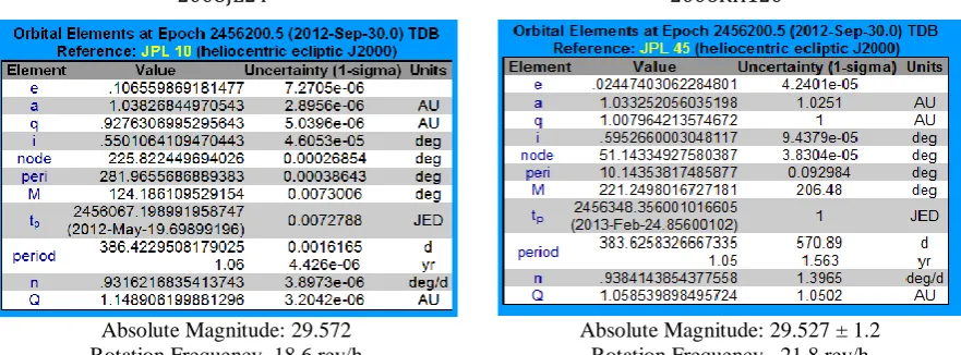
[image:2.595.78.519.441.604.2]After an extensive analysis of a range of possible target asteroids, two small bodies have been shortlisted. Table 1 summarizes both known orbital and physical data on objects 2008 JL24 and 2006 RH120. However these objects will both undergo a very close approach to Earth: asteroid 2008 JL24´s closest approach occurs during 5th March 2026 with a minimum distance to Earth of only 0.061AU, while asteroid 2006 RH120’s closest approach occurs during 9th October 2028 with a minimum distance of 0.027 AU.Both objects can be assumed to be 4 m diameter asteroids with a mass of 130 tons. Given the mass and size of the two objects the estimated average density is 3879.4 kg/m3 for both objects, a bit higher than S-class asteroids and lower that M-class asteroids.
Table 2
reports the typical estimated density of S-class, C-class and M-class asteroids and their albedos along with the density and estimated albedos of the selected targets.Table 1. Orbital elements and physical characteristics of 2008 Jl24 and 2006 RH120
2008JL242 2006RH1203
Absolute Magnitude: 29.572 Rotation Frequency~18.6 rev/h
Absolute Magnitude: 29.527 ± 1.2 Rotation Frequency~ 21.8 rev/h
The ephemerides of both objects are relatively uncertain and a rendezvous may pose a serious challenge. Indeed, if the asteroids are visible from Earth before the rendezvous, the ephemerides of these objects may be updated and the uncertainty significantly reduced. If radar observations can be scheduled before the encounter, some physical characteristics may be extrapolated such as its shape and rotational state. Unfortunately, as shown in Table 3, no radar observations will be possible in the coming two decades and only 2006 RH120 will be visible from Earth during June 2028.
2
http://ssd.jpl.nasa.gov/sbdb.cgi?sstr=2008%20JL24
3
Table 2. Density and albedo of 2008 JL24 and 2006RH120.
The values are also compared with typical asteroid data as in Chesley et al. [2]. ρ (kg/m3) pv
C-class 1,300 0.06
S-class 2,700 0.18
2008JL24 3,879.4 0.1637
2006RH120 3,879.4 0.1707
M-class 5,300 0.12
Standard NEA 2,600 0.154
. Table 3. NEO properties and next observation opportunities according to NHATS4
Figure 1. Visual magnitude of a) asteroid 2008 JL24 and b) asteroid 2006 RH120 from Earth and from a SC on a preliminary transfer trajectory
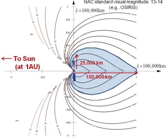
Figure 2. Observability diagram of a faint object from a vantage point at 1 AU
4
http://neo.jpl.nasa.gov/nhats/
[image:3.595.165.434.489.710.2]A more detailed account of the visual magnitude of the objects as seen from the Earth and the spacecraft during a possible rendezvous trajectory is shown in Figure 1. It can be seen, for example, that asteroid 2008 JL24 approaches the Earth twice during 2026. The best transfer opportunity for 2008 JL24 requires departing from the asteroid just before the second close approach, and as the spacecraft approaches the asteroid the visual magnitude of the asteroid as seen from the spacecraft (red line) decreases very quickly. 2008 JL24 reaches only a minimum magnitude around 25 as seen from Earth, slightly above 24, which is the minimum required to be detected by Earth based surveys (horizontal blue dashed line). Assuming a narrow angle camera with a standard limiting magnitude of 13-14 (horizontal yellow dashed line) the spacecraft would be capable to see the asteroid only during the last few days before rendezvous. On the other hand, 2006 RH120 appears to be a more advantageous target since both the asteroid and the spacecraft can be seen from Earth during the approach. Finally, Figure 2 shows the region around the spacecraft where an asteroid of 4 meters diameter will be visible by a standard narrow angle camera at 1AU distance from the Sun (approximately that of the spacecraft during the transfer). In the figure the spacecraft is in the origin of coordinates, the Sun direction is towards the negative x-axis, and each curve encloses the region where an asteroid 4 meters in diameter would be seen from the spacecraft. The area where the asteroid can be seen lies mostly away from the Sun as the Sun is illuminating the asteroid. It can be thus understood that not only will the asteroid be visible during the last days of approach, when at very close distances, but also the approach needs to ensure a certain geometrical configuration with the Sun and the asteroid.
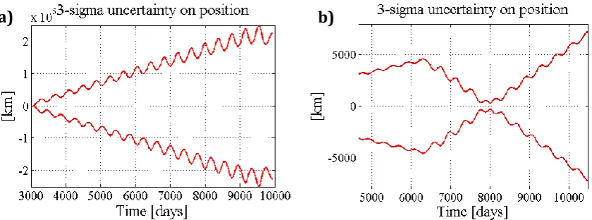
Figure 3. Uncertainty in asteroid position for a) asteroid 2008 JL24 and b) asteroid 2006 RH120 as a function of time with the date of arrival at 10479 MJD2000.
Despite the fact that the Orbit Condition Code of 2008 JL24 and 2006 RH120 is initially considered acceptable for both objects, a preliminary GNC analysis shows that the error in position for objects 2008 JL24 is too large for a feasible rendezvous. This is due to the combination of the level of uncertainty on the object ephemeris and the timespan since the last observation campaign. The last observation of the object occurred during 2008, and no future observation campaigns will be possible until the rendezvous of the spacecraft with the asteroid in 2027. As shown then in Figure 3, this represents a build-up of uncertainty in position due to runoff drift that is equivalent to a 3-sigma error in position of about 250,000 km from the centre of the ellipsoid of uncertainty. As indicated by Figure 2, detection of the asteroid by the spacecraft may then not be straightforward and the risk of completely missing the asteroid may as a consequence become very high. This however could be avoided, if by the launch time, Earth based telescope technology has improved sufficiently to allow detection of objects with visual magnitude between 25 and 26, or if spacecraft narrow cameras have also increased significantly their limiting visual magnitude. The knowledge of the ephemeris of 2006 RH120 is however much more accurate, which allows a reliable rendezvous even without further observation campaigns. Moreover, 2006 RH120 will be visible from Earth during the approach of the spacecraft to the asteroid, strengthening then the case for this target as baseline choice.
3. Deflection Principle
The deflection thrust FSUB is generated by sublimating the surface of the asteroid as it rotates under the spot light
of the laser beam. The thrust FSUB is computed as the product between the mass flow generated by the ablation
process
m
, the speed of the ejectav
and the scattering factor :SUB
F
vm
(1)The mass flow per unit area
is computed from the simple one-dimensional energy balance:
*
1
I RAD COND v
P
Q
Q
E
(2)where PI is the power density at the spot, QRAD is the heat loss through radiation and QCOND is the heat loss
through conduction. The extended sublimation Enthalpy *
1
2
0
2
v V P s V s o
E
E
v
C
T
T
C
T
T
contains the Enthalpy of complete sublimation Ev and the losses in the Knudsen layer. Here Ts is the sublimation
temperature, T0 is the reference temperature 273K and Cv and Cp are the heat capacities at constant volume and
constant pressure of the sublimated material. The mass flow per unit areas is then integrated over the illuminated area to give:
0 2 max out in y t rot t
m V
dt dy (3)where Vrot is the velocity of rotation of the surface under the sport light. The velocity of the ejecta is
computed with the simple average of the Maxwell distribution:
8
b sa
k T
v
M
(4)where Ma is the molecular mass of the ejecta, and the scattering factor is the integral of the trigonometric part of
the density distribution of the ejecta[10]:
2
2 1
*
2
( , )
cos
2
2
k SPOT P MAX SPOTd
r
K
r
d
(5)where * is the density of the ejecta at the spot,d
SPOT is the diameter of the spot, r is the distance from the spot
and is the elevation angle with respect to the spot surface. For more details on the model please refer to [15]. The density distribution is also used to compute the contamination factor
(6) That multiplies the output power from the laser to give the power density at the surface:
g M L
I IN spot
P
P
A
(7)where PIN is the power input to the laser, L is the efficiency of the laser, M is the absorptivity of the material, g is the energy absorbed by the ejected gas and Aspot is the area of the spot. The thinkness of the deposited material is computed from the equation:
2
cos
vf ldh
v
dt
(8)where ψvf is the view angle i.e. the angle between the normal to the surface and the surface-to-spot vector. To account for the expansion of gas in a vacuum the average velocity is multiplied by a factor of two. The denominator ρl is the layer density. Based on experimental results, for olivine, this is 250 kg/m3
[12].
3.1.Momentum Coupling and Mass Efficiency Analysis
It is now interesting to assess the possible impact that the laser ablation system can have on the design of a deflection mission and compare the laser system to other contactless deflection methods. Two metrics can be considered: the momentum coupling that relates the achievable thrust to the power installed on the spacecraft and the mass efficiency that relates the achievable deflection to the mass of the system required to produce that deflection. From the thrust delivered by the sublimation process and the input power to the laser system one can derive the momentum coupling coefficient:
sub m IN
F
C
P
(9)This definition is slightly different than the one found in Phipps et al.[8] as the interest here is to size the power system onboard the spacecraft. The power input to the laser is:
1 2 AU SA IN P S
AU
P
A
P
R
(10)In order to better understand the impact on the system size of the laser one can take, for comparison, some existing electric propulsion systems. The RIT-22 has an Isp of 4500s, at a thrust of 150mN and 5000W of input
power of 460 W, therefore its momentum coupling would be 1.63x10⁻⁵ N/W. SPT engines are expected to have a higher momentum coupling, for example a PPS1350G has demonstrated an average thrust of 67 mN at 1190 W with an Isp of 1540 s, therefore the expected momentum coupling would be 2.79x10⁻⁵ N/W. The momentum
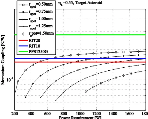
coupling as a function to the input to the deflection system is represented in Figure 4 for the target asteroid and for a laser efficiency of 55% and is compared to the momentum coupling of three electric propulsion systems. Note that the assumption here is that the efficiency of ion engines does not change with the power level. This is not generally true as for very low propulsion level the efficiency currently drops from 40% or less. The momentum coupling of ion engines is therefore expected to be lower for low thrust levels. Figure 5 shows the dependency of the input power to the laser and spot size to the desired momentum coupling and thrust level for a laser efficiency of 55%. Figure 5a shows the dependency of the input power to the laser on the desired momentum coupling and thrust level while Figure 5b shows the dependency of the spot radius on the desired momentum coupling and thrust level. It can be seen that if the spot radius can be controlled down to fractions of a millimetre the momentum coupling can be extremely high requiring small size laser with little power input. For example a 300 W laser can deliver almost 2x10⁻⁵ N/W at a thrust level of 5 mN if the spot size radius could be reduced to 0.2 mm. This is of course very demanding on the optical system. As it will be shown in section 3.4 controlling the beam radius down to 0.1 mm is possible but would require a fine control as the Rayleigh distance drops rapidly below 1m. A spot radius between 0.6 and 1 mm is more reasonable and allows for a relaxed control on the distance, being the Rayleigh distance between 1.5 and 4 m. This implies operating at higher thrust levels and power inputs for a constant Cm or at lower Cm. In the following it was decided to operate a suboptimal momentum coupling, around 1.16x10⁻⁵ N/W, to keep the spot radius close to 1 mm and significantly reduce the control of the optics.
Figure 4. Momentum coupling for different spot sizes (laser efficiency 55%).
Figure 5. a) Input power and b) spot radius as a function of momentum coupling and thrust level One can now consider the total mass of the system required to produce a deflection action. The primary requirement for the Light-Touch2 mission is to produce a 1 m/s delta velocity onto the asteroid through the
[image:6.595.169.416.304.502.2]deflection manoeuvre. Since the laser produces a low-thrust deflection manoeuvre, this quantity can be computed by integrating the resulting thrust on the asteroid over time:
stop ablation
start ablation sub I
NEO
F
t
v
dt
m
t
(11)where
m
NEO is the mass of the asteroid which is decreasing due to sublimation. The overall mass of the ablation system includes the laser itself, the power system dedicated only to pumping the laser and the radiators dedicated only to rejecting the heat of the laser. The area of the radiators AR can be derived by the simple steadystate thermal equation
Q
laser
RA T
R R4assuming an emissivity of R=0.9 and a temperature of the laser of TR [image:7.595.75.512.192.508.2]= 278 K. From the system design one can define the specific mass of the power system is P = 42 kg/kW.
Figure 6. Total deflection system mass as a function of the Dv: a) RIT10 vs laser with Cm = 1.4x10⁻⁵ N/W, b) PPS1350G vs laser with Cm = 1.4 x10⁻⁵ N/W, c) RIT10 vs laser with Cm = 1.16 x10⁻⁵ N/W, d) PPS1350G vs laser with Cm = 1.16x10⁻⁵ N/W. No gravity losses are included and the asteroid mass is 130x103kg.
The mass of the laser system is therefore:
4
(1
)
INLS P IN R L L
R R
P
m
P
m
T
(12)where mL is the mass of the laser itself plus the optics, R = 0.5kg/m2, is the mass of the radiators. The mass of
the EP system includes the mass of two engines, the mass of the related power system, the mass of the radiators, the mass propellant and the mass of the tanks. The mass of the radiator and power system is computed using the same figures and assumptions used for the laser system except for the efficiency of the engine that is always equal to 60%. This is a rather optimistic assumption as the efficiency does not scale with the thrust level. The mass of the propellant is simply
m
p
2
F
EP
t
thrustI g
sp 0, the mass of the EP system is therefore:4 0
2.2
EP(1
)
IN2
EP thrust P IN R EP e
sp R R
F
P
m
t
P
m
g I
T
(13)where me is the mass of a single engine, Isp is the specific impulse of the engine and hEP is the efficiency of the
EP system. The assumptions here are that: the mass of the tanks is only 10% of the mass of the propellant, two engines are on at the same time, the efficiency of the engine does not change if the engine is scaled down, the
a)
b)
mass of the propellant has no impact on the structural mass of the spacecraft. Note that the last two assumptions are quite strong as the efficiency of EP system goes down as the size goes down. For example current nano-ion engine achieve 40-50% optimistically while engines delivering hundreds of mN can achieve 60% efficiency. The efficiency and Isp used in the comparison is the one declared buy the builders for each one of the engines
although the thrust and mass were scaled down linearly. Figure 6 shows the mass of the deflection system against the achieved vI assuming that the mass of the power and thermal system remain constant, and so does
the thrust applied to the asteroid. The mass of tanks and propellant is growing linearly with the vI in the case of
the EP system and dvI grows linearly with time. Figure 6a shows a comparison of the laser system against the
RIT10 assuming a Cm = 1.4x10⁻⁵ N/W for the laser while Figure 6b shows a comparison of the laser system against the PPS1350G for the same laser Cm. It is clear that of the laser system had the same Cm of the EP systems the mass would be always in favour of the laser system for a given vI as the radiator mass has a small
impact and the mass of the power system would be the same. Figure 6a and b, however, shows that even if the laser is operating at a lower Cm than the EP system still there is an advantage in using the laser especially as dvI
increases up to the point in which the laser system is always better than the EP for any vI. Note that at Cm = 1.4
[image:8.595.77.517.283.447.2]x10-5 N/W the requirement on the optics is very reasonable in particular for thrust level of 10 mN or higher. In the following, as explained before, we decided to work at a suboptimal Cm to relax even further the optics. Figure 6c and d show a comparison of a laser system operating at Cm = 1.16 x10⁻⁵ N/W against the RIT10 and PPS1350G. The laser still overcomes the PPS1350G but falls behind the RIT10 at low thrust levels requiring a mass that is 5-7 kg higher.
[image:8.595.77.517.474.633.2]Figure 7. Thrusting time required to achieve 1m/s: a) 20m shooting distance, b) 30m shooting distance
Figure 8. Thrusting time required to achieve 1m/s: a) 40m shooting distance, b) 50m shooting distance This analysis considered no gravity losses and no contamination. It also assumed that the mass of the propellant implies an increase of the mass of the tanks only. The effect of contamination has an impact on the required thrusting time for the laser system. If the contamination and the distance from the Sun are included one can compute the required thrust time to achieve a vI = 1 m/s for different PIN and different spot sizes. The distance
from the asteroid has an impact on the contamination level therefore different simulations were run within a range of 20-50 m from the asteroid. The radius of the spot was taken between 0.8 and 1 mm. The input power to the laser was taken in the range 850-1000 W.
Figure 7 to Figure 8 represent the contour line of the thrusting time required to achieve a delta velocity on the asteroid of 1 m/s for distances from the asteroid of 20, 30, 40 and 50 m. The thrusting time is here considered to
a)
a)
b)
be the time required for continuous thrusting from the time at which the one-month firing laser test is initiated (383 days after launch).
Note that with a distance from the asteroid of 50 m the best results are achieved as the contamination is lower. The assumption is that the spacecraft is trailing the asteroid and the solar arrays have a maximum aspect angle of 15 degrees with respect to the impinging plume. The laser was shown to have a self-cleaning effect on the impinging plume therefore the contamination is considered to be negligible[12]. At a distance of 50 m the contamination of the arrays induces a 5% reduction of the power and the target variation of the velocity can be achieved in a fraction of a year of push time. From Figure 9 one can see that if at a nominal distance of 50 m, with a 1070 nm frequency of the laser, the radius of the spot is 0.8 mm and the diameter of the reflector is 75 mm, an increases of up to about 1 mm of the radius is to be expected if the distance of the spot changes by 1.9 m. This means that a fully uncontrolled focusing of the beam within a range of ±1.9 m from the expected focal point would lead to a required push time that is between 165 and 220 days for a power input of 860 W. This gives a lot of flexibility on the control of the beam as the distance from the spot needs to be known with an accuracy that is of the order of a few meters. A lower PIN is possible though a smaller spot size would be
required and longer push time. In the second iteration it was decided to conservatively take PIN= 860 W to have
a large margin on the control of the beam and the push time.
3.2.The laser System
The laser system is composed of a laser diode coupled to a fibre plus a collimating optics. From recent developments supported by DARPA and realised by nLIGHT one can see that laser diode demonstrated 80% efficiency or higher with output power for single elements of up to 350W. Stacks can go up to few kW. In particular experimental results have demonstrated wall-plug efficiencies of about 83% at 138K and 76% at 283K. Cryogenic temperature can represent a serious challenge especially over long periods of time. A laser system operating at temperatures between 273 and 283K seems more reasonable and poses less demanding constraints on the thermal control system. The beam quality of these laser diodes is not high enough to produce the right power density. These laser diodes can instead pump fibres that at present have already reached an 83% optical to optical efficiency. The coupling between fibres and laser diode requires some attention but efficiencies between 80-90% are achievable. It is therefore reasonable to expect a diode+fibre coupling with an overall efficiency between 50% and 57% with the possibility to increase the overall efficiency to 62% by further cooling the laser. Heat rejection is required at two stages: at diode level and then at fibre level. Assuming, for example, a 1kW output power the required heat rejection at diode level is between 200 to 240W while at fibre level is between 130 and 136W. At this point it is interesting to note that the efficiency of the laser system is comparable to the one of a ion engine and presents the need to reject similar levels of heat. On the other hand the expectation is that fibre lasers pumped by diodes will not significantly improve in the future. Therefore, one can assume a theoretical efficiency upper limit of 70% corresponding to perfect coupling and cooling. An alternative to the use of fibres coupled with laser diodes is to use a direct solar pumping using concentrators and semiconductor disks. This technology is however considered to be less mature than a fibre+diode solution and with a less clear technology roadmap. Therefore, this option will be retained as back-up. The main advantage of it is the reduction in the power system mass. At present, however, directly pumped laser demonstrated relatively low efficiencies, below 10%, with the exception of recent lab experiments that demonstrated very high efficiencies but at very low power. Fibre coupled diode lasers come in a diverse variety of wave length and are heavily used in industry for different applications presenting already efficiency between 30 and 46% off the shelf with power levels that can go up to 1kW. The choice of the wavelength has an impact on the total energy absorption at the surface of the asteroid and also on the beam quality, i.e. the ability to focus the beam over long distances.
3.3.Beam absorption
For S-type asteroid the albedo aS is between 0.1 and 0.3 and the relative reflectivity with respect to the central
frequency at 505nm has a peak of 1.2 between 750 and 800nm [11]. A wavelength higher than 800nm or lower than 750nm would significantly increase the absorption. In the following it was decided to consider the wavelength of an existing industrial kW class fibre couple diode laser, operating at 1070nm. Although at this frequency the absorption is very good it was decided to keep the 20% increase in albedo to be conservative. As it will be explained in the following section a 1070nm laser might not be ideal for the control of the beam as the divergence is proportional to the wavelength. On the other hand the frequency is ideal to maximise output power.
3.4.Beam Focusing and Control
to control the spot area depends on the laser beam quality identified by the M2. The M2 defines how much the beam departs from an ideal Gaussian beam: the smaller the value the better the quality of the beam. This translates directly into the ability of the beam to achieve a small focused spot with nearly all the laser power tightly focused. The idea is to start from collimated beam that appears a point source, expand the beam and then refocus the expanded beam to the desired target spot at the desired distance from the source. Figure 9 shows the relation between the beam diameter at the exit of a focusing mirror and the focused spot radius at 50m from the source and for a laser frequency of 1070nm. The distance from the focus, over which the beam will double its area is known as the Rayleigh range, ZR [14]. It is a measure of the focussing power of the beam. The distance between the corresponding points on either side of the focus is then 2 ZR. The plot in Figure 9 shows this distance as a function of the beam diameter.
Figure 9. Variation of the beam radius and twice the Rayleigh range (2zr) at the beam focus with the beam diameter at the exit of the telescope system.
3.5.Sensitivity to the Rotation Speed of the Asteroid
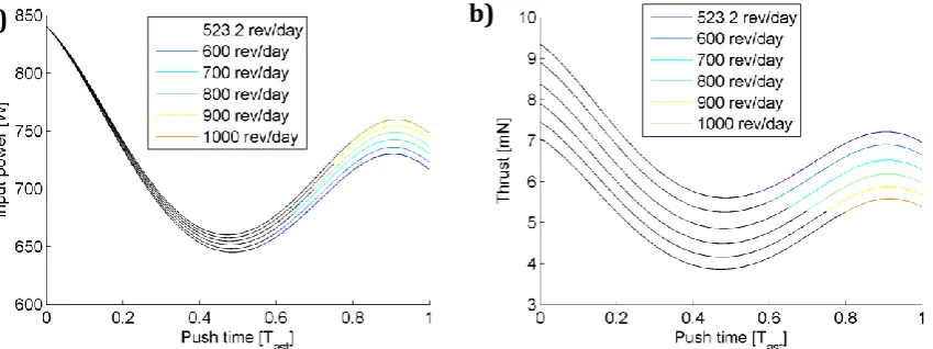
[image:10.595.80.505.502.661.2]The thrust output from the ablation process depends on the rotation of the asteroid. It has to be noted that the current assumption is that the ablated spot is at maximum distance from the rotation axis no matter which strategy is considered. Hence the velocity at which the surface is passing under the laser light is maximal in all cases. Table 4 gives an idea of the variation of the required thrusting time as the initial rotation speed of the asteroid increases from the current estimation to 1000 revolutions per day. Note that this analysis does not consider the refocusing of the beam that can improve performance as the rotation speed increases. The black line represent the portion of the trajectory where ablation is on. Ablation stops when 1m/s is achieved
Figure 10. a) Input power as function of the rotational speed of the asteroid, b) Thrust on the asteroid as function of the rotational speed of the asteroid.
Table 4. Thrusting time as function of the rotational speed of the asteroid.
Rev/day 523.2 600 700 800 900 1000
Thrusting time [days] 218.89 233.84 253.70 273.35 293.40 311.50
Figure 10a, and Figure 10b show the time history of the input power and generated the thrust level for different possible rotation speeds of the asteroid.
4. Transfer Analysis
Asteroid 2006 RH120 follows an orbit similar to that of the Earth, and the transfer costs is very low as demonstrated in Figure 11 where the cost of a simple two-impulse transfer is represented against the departure date and transfer time.
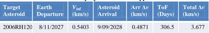
[image:11.595.133.465.147.372.2]Figure 11. Porkchop plots of the chemical propulsion transfers for 2006 RH120 Table 5. Chemical propulsion transfer opportunities
Target Asteroid
Earth Departure
Vinf (km/s)
Asteroid Arrival
Arr Δv
(km/s)
ToF (Days)
Total Δv (km/s)
[image:11.595.126.472.414.470.2]2006RH120 8/11/2027 0.5403 9/09/2028 0.4871 306.5 3.677
Table 5 presents the best transfer opportunity for 2006 RH120. The figure of merit used to evaluate the transfers (and also represented on the colour scale of the porkchop plots) is the total Δvof the interplanetary trajectory comprising the escape burn, a possible DSM and the final rendezvous burn at arrival. For the escape burn, departure form a 400x400 circular parking orbit direct into a hyperbolic escape with the optimal infinite velocity was assumed to calculate the Δv. This does not take into consideration the type of launcher or any constraint in declination, which will be further evaluated when the selection of target and type of transfer is narrowed.
5. Mission Timeline
The mission will be conceptually divided in 9 phases characterized by different operational modes.
1. Launch: Escape is achieved by means of the main chemical engine. Before the spacecraft is injected into the interplanetary transfer trajectory by an hyperbolic escape manoeuvre, 2 apogee raising manoeuvres are performed to raise the apogee from the GTO in which a PSLV launcher inserts the spacecraft.
2. Commissioning: Immediately after separation, the spacecraft will autonomously de-tumble, deploy its solar arrays and acquire a coarse three-axis stabilised Sun-pointing attitude. After launch, a tracking campaign will be performed in order to verify the interplanetary transfer trajectory and, if required, a first Trajectory Correction Manoeuvre (TMC-1) is implemented, 7 days after departure, to correct injection errors. Before putting the spacecraft into hibernation mode, all its functions will be checked and the payload will be commissioned.
4. Transfer: departure, interplanetary transfer and arrival.
5. Early Encounter/Arrival phase: One month before the designed Rendez-Vous Manoeuvre, RVM, (considered the arrival time) the spacecraft will be resumed. Ground station will track the spacecraft to implement possible corrections and if necessary re-plan the rendezvous manoeuvre. RVM leaves the spacecraft trajectory in a sun-asteroid direction in order to reduce the illumination angle (sun-asteroid-spacecraft), which results in a higher apparent visual magnitude. 3 days before RVM, occasional picture will be taken and relayed to calibrate the following instruments: narrow angle camera (NAC), wide angle camera (WAC) and start tracker (STR). The main engine will perform the 391 m/s manoeuvre at a distance of approximately 60,000 km from the estimated position of the asteroid, thus reducing the relative velocity with respect to nominal asteroid’s trajectory to50 m/s. A ground supported campaign will verify the spacecraft’s trajectory. Then the spacecraft will enter a target detection mode to acquire and identify the asteroid LOS in the NAC, and the asteroid’s ephemeris will be improved. Line Of Sight (LOS) measurements will be acquired from different angles and combined with radiometric navigation data. After 1 week the acquisition of the asteroid is assured. 2 Optical-Nav-Based Early-Encounter-TCM, EE-TCM-1 (10 days after RVM), EE-TCM-2 (12 days after RVM) will reduce relative position uncertainty from 5000 km by three orders of magnitude to <10 km. The phase concludes with Far Approach Preparation Manoeuvre (FAPM), 14 days after RVM at about 5000 km distance.
6. Far-Approach (11 days): The far approach trajectory phase starts with the FAPM. A sequence of 3 subsequent manoeuvres by the RCS will reduce the relative distance from 5000 km to 10 km to allow start of autonomous operation:
• 1 day later, Far Approach Start Manoeuvre (FASM). • 5 days later, Far-Approach-Mid Manoeuvre (FADM). • 5 days later, arrival, Far-Approach-End Manoeuvre (FAEM).
This phase ends at the Approach Transition Point (ATP), 11 days after the beginning of this phase. At this stage (about 10 km from the asteroid) the NAC is able resolve the target to > 100 pixels. At ATP the relative trajectory knowledge will accurate to 1 km in position, thanks to a high number of LOS measurements taken from different angles.
7. Close-approach (11 days): The close approach trajectory phase starts at ATP. In this phase the spacecraft will autonomously approach the asteroid and allow ranging sensor acquisition. A sequence of dog-leg manoeuvres through way-points will be performed to allow LOS-based relative navigation accuracy to improve to < 20 m in the range direction; at the same time the spacecraft will acquire ranging sensor and arrive to Hold Point 1, HP1, at 300 m from target. Final relative navigation accuracy shall be almost optimal (a part from fine-calibration). The sequence of operations is:
• Preparation of the autonomous LOS-based-GNC.
• Dog-Leg Autonomous Approach Segment, starting 2 days later
• Spacecraft autonomously travels through 6 way points, 1 per day, to reach a 1 km distance from asteroid (Sun-NEO-SC angle of 45 deg)
• Waypoint 6 coincident with Hold Point 1 HP1 where it holds one day in preparation for next step • 9 days after start, the Final Close Approach Segment starts, with an autonomous approach to 300
m from asteroid (Sun-NEO-SC angle of 0 deg ).
• This 6-hour approach is supervised from ground. During the approach, the ranging sensor is acquired
Then, for 2 days, GNC equipment status is verified while autonomous GNC controls the spacecraft to remain within a 5 m-wide control box. The end of the close autonomous approach is 11 days after it started..
8. Transition to the Close Operative phase (26 days) starts at the end of Final Close Approach Segment. The spacecraft follows subsequent hyperbolic arcs until it is about 25 radii (50m) from the asteroid, in the proximity operations point. During this phase, GNC system is tested and calibrated, including algorithms, sensors and actuators, and optimal asteroid orbit determination is performed. Its sub-phases are:
• Loose autonomous position control – range is controlled to remain between 200 and 300 m. The lateral (cross range) control box is 4 m wide. During 20 days, the low amount of RCS firings to remain in this control box, will allow precise calibration of the sensors, precise radiometric determination (combined with relative measurements) of both the asteroid and the S/C. The phase allows modelling the asteroid shape and its rotational state via image and autonomous-processed (FEIC) extracted feature points (through a dedicated circuit) and high amount of NAC images sent to ground.
• 20 days later, the spacecraft is allowed to approach to 100 m range, HP3, and perform full autonomous GNC test in a control box (range between 98 and 102 m lateral control 1 m wide). The fully autonomous operational system test is supervised and running for 3 days.
to surface between 49 and 51 m , lateral displacement < 1 m). The fully autonomous operational system is supervised and running for 3 days.
During this phase, the asteroid kinematics and shape model are built. Up to the acquisition of the final relative position the phase lasts 26 days.
9. Operative phase starts at the end of the third GNC test. Three sub-phases can be distinguished:
• Calibration and Testing (64 days) The spacecraft calibrates and tests the full system including ablation laser, and assess operational capability of the system. The aim of this phase is to perform the procedure validation and build trust on the autonomous system:
- For one week, the spacecraft will perform the Initial Ablation Test Campaign (5 minutes, 30 minutes, 1 hour, 6 hours, 1 day). Autonomous GNC, science, health status and radiometric navigation data are collected and verified on ground.
- For the following week the Ablation Campaign will run with full autonomous operational setting equal to the actual ablation campaign, followed by a 10 day combined radiometric + relative orbital determination campaign.
- This is followed by one Month-Long Ablation Campaign, followed by a 10 day combined radiometric + relative orbital determination campaign and full testing of the system and results. - One month and two weeks after it has started, the procedure validation and calibration will allow
the operator to trust the system in order to start the full campaign..
• Full Operational Phase The bulk of the operations towards the main Mission Objective in which the laser efficiently imparts ∆v to the asteroid by ablating it. The spacecraft will actively control relative position and attitude and estimate the imparted ∆v.
- Sequence of 90-day ablation plus 10 day-measurement process
o The ablation causes the asteroid to accelerate ~0.05 µm/s2 (within the range 0.04-0.075 µm/s2)
o Laser operates for 6 full days continuously, then data is relayed to Earth for 1 day (to Harwel), including camera images, health, house-keeping and radiometric navigation data. 13 sequences of ablation/data-relay operations are performed in a batch.
- Followed by a 10-day a radiometric navigation campaign using radiometric and ranging from the Harwel ground station and 2 ∆DOR measurements from ESA’s DSA network.
- Three of these sequences complete the baseline mission. Nominally, all mission objectives shall be attained at this point, including the successful change of NEO velocity by 1 m/s, full precise characterization of the asteroid rotational and orbital state confirmation of the change in orbit, as well as additional scientific objectives.
- This will happen 723 days after launch, at an Earth-NEO distance of 0.404 AU.
• The Extended Operational Phase This is an optional operative phase, which comprises further ablations and asteroid orbit determination and characterization. Once the ground team considers that the objectives of the mission have been accomplished, the phase can be interrupted and the remaining time to the 3 year limit can be used to collect more images, perform autonomous GNC approach/touch-down to the asteroid or other technology demonstration or experiments. Starting from the alread y accurate orbital determination results from the previous segment, 20 days of Doppler and ranging from Harwel will follow, to allow improving the accuracy to halve its initial value (1σ of ~2 km in position). Then the extended operational phase will foresee:
- Sequences of 90-day ablation plus 10 day-measurement processes, exactly like the Full Operational Phase.
- The third optional sequence finishes 1043 days after launch 52 days before the 3-year limit. - A reduction in the amount of relayed data for supervision (to still be sent to Harwel). Eventually an
alternative station for orbit determination is used in the extended operational phase.
Due to the continuous change of the orbit of the asteroid, and the perturbations acting on the spacecraft (recoil of the laser, solar radiation pressure and plume impingement) the orbit of the spacecraft will need to be adjust ed to maintain the close formation motion. The control, implemented by RCS thrusters, aims at maintaining the spacecraft’s relative position within a control box. The on-board system is able to estimate the accelerations the spacecraft. This information can be integrated in time to measure the overall v imparted to the asteroid by the ablation. A second method to assess this value is through the ground-based radiometric measurements from Earth, where the position of the spacecraft can be tracked to the accuracy required to establish the new ephemerides of the asteroid.
6. Navigation and Control
• Size of the target Asteroid – Gravity. 2006RH120 is extremely small . Hayabusa was considered a mission to a very small body. Itokawa, its target, is a low density rubber-pile asteroid of 535 × 294 × 209 m size. Its gravity force at 10 000 and 50 m is, respectively, 10 µN and 382 mN for the light 400 kg spacecraft. At the same distances, the 130 Ton–target of LightTouch2 will exert a force on the ~560 kg spacecraft of only 0.05 nN and 2 µN, respectively. This is 6 orders magnitude lower than Itokawa. The gravity field of the asteroid, for approach, rendez-vous operations is almost negligible in our case. For what concerns the GNC, it can be considered a small perturbation in the dynamics wit h respect to the ~40 µN Solar Radiation Pressure (SRP). The implications in the GNC strategy and design are numerous: during close approach operations, the whole dynamics can be reduced with good approximation from the complex 3-body dynamics to a simpler 2-body dynamics. For proximity operation, stable terminator orbits do not exist, therefore, instead of controlling the spacecraft around a stable terminator orbit, the GNC needs to counter-act the effect of Solar Radiation Pressure to remain in a non-stable operational relative position Safety and control authority also require a different approach to the design. At the proposed operational distance the asteroid barely attracts the spacecraft, although if the spacecraft is placed in between the Sun and the asteroid the SRP is pushing the spacecraft towards the asteroid. Thus, the requirements on the RCS come from the SRP rather than the gravity of the asteroid. During ablation the problem is quite different as the spacecraft is subject to the small but not negligible plume and the asteroid is constantly changing its state of motion. Linearised equations based on the assumption of a constant angular momentum do not consider this added nonlinearity to the motion of the spacecraft that instead need to be considered with care.
• Size of the target Asteroid – Visual Magnitude. The absolute visual magnitude of Hayabusa’s Itokawa is 19.2. The 160-m-wide 2002AT4, 21 absolute magnitude target of Don Quijote could be detected from a distance 2500 000 km. 2006RH120 worst-case magnitude (3σ) is 31. The Narrow Angle Camera (NAC) from Rosetta would detect it at 40 000 km from the most favourable illumination angle (Sun-asteroid-SC angle of 0 deg), that is, 3 orders of magnitude below the distance of detectability of what is already considered a small body. Additionally, its ephemeris knowledge are in the same order of magnitude of the distance of detectability. To cover the uncertainty region (3σ) in position of 5000 km from the detectability distance, the critical detection process (against a bright sky) needs to be repeated for different pointing directions of the NAC Fields of View (FOVs). That is, scanning manoeuvres need to be performed with implications in the early encounter trajectory. At distances of 1 km the asteroid will be barely resolved in the Wide Angle Camera (WACs) FOV (will span than 10 pixels) and at operational distance it will be 50-pixels wide. This shifts the NAC’s relevance as a detection and far approach sensor to serve also approach and proximity. In fact, the 2-4 m asteroid will fit tightly in the FOV of the NAC at the proximal distance of 50 m, making the sensor suitable for rotational state estimation and asteroid characterization.
• Duration of Operations. Contrarily to sample return, impact or orbiting characterization missions, LightTouch2 aims at remaining in an unstable point relative to the asteroid while perturbing its orbit and being affected by perturbing forces and torques from Solar Radiation Pressure, impingement form the ablation plume, recoil from the laser for 2 years. Even though the forces to be counteracted are small, they are always present. The issue of the life-time of GNC components becomes relevant as the number of RCS actuations rises to the tenths of thousands, the same order of magnitude of their operational limits. The concurrent assessment of RCS activation logic algorithms for position control, similar to those used in attitude control, to save mass, and definition of control windows that are loose enough to allow excursions between actuations, is necessary.
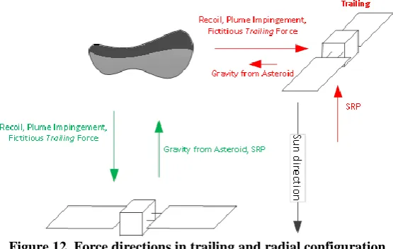
Figure 12. Force directions in trailing and radial configuration
In both configurations, the GNC has to estimate and control the state of the spacecraft that is subject to the following effects:
• Laser recoil: Reaction force induced by conservation of momentum upon the projection of laser photons. The torque associated with this force is assumed to be well known (and negligible) as is located close to the CoM. Acts to push the spacecraft away from the asteroid.
• Gravity force: pull towards the 130 000 kg asteroid. Torque from gravity gradient is negligible. • Gravity gradient (Sun): ~1x10⁻³ µN at 50 m.
• Solar radiation pressure: exerted mainly in the 7.4 m2 solar panels, but also partially in the S/C body. The spacecraft is nominally sun pointing, but the nominal value still changes with the distance to the Sun. Appart from that, it can be considered a stochastic value where the magnitude changes by 20% (conservative) with respect to its nominal, where this excursion has a time correlation of 7 days. A torque arises from this force when the centre of pressure (CoP) does not coincide with the centre of mass. • Plume impingement: Caused by the jet of ejecta plume hitting the body and solar panels of the
spacecraft. Pushes the spacecraft away from the asteroid. The magnitude depends on the cross section of the exposed surface. If ablating from radial direction, the ejecta will hit the full back surface of the solar panels and hence be larger than if ablating from trailing position, where it will directly hit the (smaller in area) solar panel shields (the solar panels are perpendicular to the SC-NEO direction). The torque is largely uncertain as the position of the centre of pressure for this force varies.
[image:15.595.107.488.515.664.2]• Deflection induced: a fictitious force arising from the accelerating local frame. The frame is centred in the asteroid’s CoM, which is, through ablation, thrusting with a 10 mN force, thus accelerating at 0.077 µm/s2. The change caused by this acceleration is equivalent to a force, when seen in a local frame of about 42 µN.
Table 6. Modelling of acting forces at operating distance
Force µN Variation Time Correlation Torque µNm*
Solar Radiation Pressure 38 20% 7 days 57
Laser Recoil 3.3 1% 1 minute <0.1
Gravity from Asteroid 1.7 10 % 5 minutes 0
Plume Impingement 20 (6) 20% 1 hour 30.0 (9)
Deflection-induced 42.3 20% 1 day 0
Total (trailing) 62.8
Total (radial) 25.5
*1 Nominal SRP also changes with distance to Sun (from 38 µN at apohelium, 1.07 AU, to 42 µN at perihelium at 1.02 AU) and attitude, apart from stochastics.
*2The laser recoild, plume impingement and deflection induced forces nominal values vary with a known model of the the distance to the sun and level of contamination. apart from stochastics. *3 The torque variation shall be of much large orders of magnitude (100% of its nominal value). Correlation times remain the same for SRP and is smaller for Plume-Impingement-induced. This is due to the variability of the arm of the force.
random value). The spacecraft is assumed to have a maximum mass of 550kg. The table shows that a significant difference exists in the balance of forces with the radial configuration resulting in having to compensate for half of the force that would have to be compensated in the trailing configuration. The radial configuration appears to be advantageous from a control point of view. On the other hand the trailing configuration would maximise the actual deflection if the ablation process is started more than one orbital period of the asteroid from a possible encounter with the Earth. Furthermore, the trailing configuration poses less problems in case of contingency as it will be shown in the remainder of the paper. An intermediate position between a fully trailing and a fully radial configuration is potentially the optimal solution.
6.1.Control law
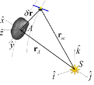
During operations the laser focussing needs to be maintained in order to produce optimal laser ablation. The optics is controlled through 1 mm max variation of the focal point of one of the mirrors, therefore it is possible to control the focal point at high frequency without moving the whole spacecraft. The design of the optics, though, is such that defocusing the laser can be tolerated so that a stringent control is not required. Nonetheless, the rotation of the asteroid would require to control the laser optics frequently to maintain a correct focussing on the spot the laser is pointing to. In order to maintain the spacecraft’s orbit against the perturbations, and at the same time keep at the minimum the number of optics adjustments, the spacecraft will be controlled by means of impulse bit from RCS. The motion of the spacecraft is defined in a Hill’s reference frame as depicted in Figure 13
Figure 13. Definition of the reference frames, including the rotating Hill frame A centred on the asteroid. The control aims at maintaining the spacecraft within a box, defined on the reference trajectory. At each instant of time the autonomous system propagates the estimated state up to the following instant of time. Then the system checks for the inclusion of the spacecraft between the boundaries defined by the control box. The control allocates an impulse bit, keeping into account the estimated acceleration acting on that direction, exploiting the dynamics to reduce the overall number of actuations. The spacecraft tends to follow a parabolic trajectory under the effect of perturbations:
2
(
)
2
in in corr
t
f
d
v
v
t
a
(14)where
d
in andv
in are the initial position and velocity error with respect to the nominal trajectory,
v
corr is the corrective impulse bit, whilea
is the acceleration. The corrective impulse bit is allocated such that the spacecraft reaches the other side of the control box, with relative velocity equal to 0.2
'
0
(
)
2
est
in corr est
est est
f in in corr est
f
t
t
t
v
v
a
d
d
v
v
a
(15)
[image:16.595.225.378.279.416.2]Figure 14. Controlled trajectory for 20cm box (a) position, (b) velocity error
Figure 15. Control in trailing configuration for 1 year (365 days) of continuous operations
Figure 16. Control in radial configuration (365days) of continuous operations
Figure 15 and Figure 16 reports the necessary Δv required to station-keep the spacecraft at 50 m in the trailing and radial configuration respectively. It has been assumed that the power available at the laser is constant for the whole period (the power is constant and the contamination factor is 1). This is a conservative assumptions, because the power at aphelion will be different and the contamination from the plume will reduce the solar arrays’ efficiency. From Figure 16 one can see that the Δv for station keeping decrease by about 2 m/s, and subsequently the number of actuations is reduced by more than 1,000. This is due to the fact that, in the radial configuration, the solar radiation pressure pushes the spacecraft along the thrust direction, thus partially counteracting the dragging force, the plume impingement and the laser recoil.
In both the configurations, the number of actuations for 1 year operations is limited under the maximum number of actuations for the thrusters (circa 40,000 life cycle). The control strategy envisages also to exploits the frequent actuations to desaturate control reaction wheels, thus, keeping the overall number of actuations by RCS thrusters at a minimum.
a) b)
a) b)
[image:17.595.81.503.261.411.2] [image:17.595.64.515.387.589.2]6.2.Asteroid Rotation / Kinematics
One important aspect of the mission is to measure the rotational state and the centre of mass of the asteroid. If one assumes that the rotation state is constant on the short period rotation axis, rotation speed and centre of mass can be estimated from a spectral analysis of a sequence of optical images[16]. A Fourier transform is applied to a time sequence of a set of tracked points (features) on the surface of the asteroid. When the rotation frequencies are coincident, it is possible to determine the spin direction of two axes by considering that the third axis can be obtained from the maximum peak in the spectrum, and then projecting the observation in a local frame which has one axis coincident with the first rotational axis. Usually asteroids of small dimension tend to rotate faster about their principal axis of inertia, and present a slow rotation around a second axis contained in the plane of perpendicular to the principal axis.
Figure 17. Asteroid rotation spin axes with markers on the surface
Using this approach, eight points on the asteroid surface need to be tracked by the on board camera. In general the position of one point on the asteroid surface, which rotates around 2 axis can be decomposed as,
1 1 2 2 0
'
(
, ) (
,
)
p
R k
R k
p
p
(16)where
p
0is the position of the asteroid barycentre with respect to the spacecraft,p
ˆ
of a point with respect to thebarycentre and
p
'
is the position of the point with respect to the spacecraft,k
1 andk
2are the spin axes,1
2
f t
1
and
2
2
f t
2 are the rotations around these axes (see Figure 17). The equation can be rewritten in terms of cosine and sine:1 1 2 2 1 2 1 2
1 2 1 2
'
cos( )
sin( )
cos(
)
sin(
)
cos(
)
sin(
)
cos(
)
sin(
)
p
a
b
c
d
e
f
g
h
i
(17)
There will be at least 4 frequencies in the Fourier spectrum in correspondence to 4 spectral peaks, which are
f
1,2
f
,f
1
f
2andf
1
f
2 . Spurious frequencies are also present and they are due to the fact we need to track more than one point because of the rotation. Nonetheless, these spurious frequencies contain low energy with respect to the four principal frequencies and thus can be easily discarded. Then a, b, .,.,i can be obtained from the Fourier transform of the time sequence data of p'. The above equations can be solved in terms ofk
1 and2
k
:
1 2 2 2
(
)
;
e
g
c
f
h
d
e f
k
k
e
e
g
c
(18)With this method, the feature point information is not collected while the selected points rotate on the opposite side not visible from the camera. The centre of mass of the asteroid can be calculated by identifying the intersection between the rotational axes, thus independently from knowing the asteroid’s mass and inertia properties:
1 2 1
0 2 2
(
)
T
(
)
k
k
a k
p
k
a i
e
Figure 18. Spectrum projected into the (a) x and (b) y coordinates
Optical observation from ground indicates that the asteroid 2006RH120 rotates with a rotational period of 21.8 revolution per hour (6.056x10⁻³ Hz). A slow rotation with 1 revolution per hour (2.778x10⁻⁴ Hz) around the local y-axis is then assumed. Four points per image are tracked every 10s, considering an error of 5% on the reconstructed position for each point; the Fourier transform results in the spectrum in Figure 18, where the rotational frequencies are clearly identified. The identified spin axes through this method were
2 [0.003 0.999 0.003] T
k , k1 [ 0.003 0.005 0.999]T, almost coincident with the actual spin axes.
6.3.Collision Avoidance/Contingency
This section contains a first assessment of the collision avoidance issues related to both the trailing and the radial configuration. If a sudden failure of the control system happens, the motion of the spacecraft is driven by the solar radiation pressure and the asteroid’s gravitational field. The SRP pushes the spacecraft along the sun-spacecraft direction while the feeble asteroid’s gravity will slightly attract it towards the asteroid. One cannot assume that spacecraft will maintain a stable attitude. In the following analyses worst case conditions have been assumed. A spacecraft tumbling will decrease the SRP contribution. The analysis for the tangential configuration is trivial, since the SRP moves the spacecraft at more than 300m in only one day, in the nominal condition as shown in Figure 19a. The yellow and green clouds represent 100 samples taken from a Latin hypercube having maximum displacement of 1m and 1mm/s consistently with the control box and corrective impulse bits.
Figure 19: Trailing Configuration: a) contingency with no control in the nominal condition maintaining a sun pointing attitude, b) contingency with no control: 25%(green), 50%(red), 100%(blue) SRP.
Even if one considers that a sun pointing attitude cannot be maintained, the tangential configuration is still safe as confirmed by Figure 19b where decreasing levels of SRP are considered and motion is propagated for 2 days. Even when the SRP is 25% of the nominal the spacecraft will be safely outside of the sphere of influence of the planet even with a 25% SRP contribution (green case).
The radial configuration needs to be considered more carefully, because placing the spacecraft exactly along the sun-asteroid direction will pose a risk in case of lack of control. In fact the solar pressure will push the
f
1
f
2
f
2+ f1
f
2- f1
[image:19.595.92.507.492.655.2]spacecraft onto the asteroid. It is thus necessary to give the spacecraft a small offset in the plane or out-of-plane direction, such that laser process is not affected. Figure 20 confirms that the close passage is safe by reporting the evolution of 100 samples from the Latin hypercube around the 10 m offset trajectory. In the worst case the spacecraft CG will be more than 3 m above the asteroid’s surface, with approximately 1 m margin considering the spacecraft actual size
Figure 20 On plane radial configuration. Contingency with 25% SRP for 10 m offset and Latin hypercube evolution.
Similarly to Figure 20, Figure 21 shows that that all the samples drawn from the Latin hypercube will fly over asteroid’s surface at more than 3 m.
Figure 21: Out-of plane radial configuration. Contingency with 25% SRP for 10 m offset and Latin hypercube evolution.
The above considerations are valid as long as the shape of the asteroid is pretty much spherical. An offset of 10 m along the tangential or the out-of-plane component allows ensures minimal safety conditions to avoid the spacecraft collide with the asteroid. Anyway the operative trajectory can be adjusted and re-planned according to the actual shape once the spacecraft have built asteroid’s map during the close approach.
7. System Design
[image:20.595.153.439.115.348.2] [image:20.595.160.440.422.615.2]