Conceptual Design of UAV Airframes
Using a Generic Geometry Service
Andr´
as S´
obester
∗, Andy J. Keane
†James Scanlan
‡, Neil W. Bressloff
§University of Southampton, Southampton, Hampshire, SO17 1BJ, UK
With the increased freedom in layout selection possible when designing
an Unmanned Air Vehicle (UAV) concept (compared, for example, to the relatively constrained and mature world of commercial airliner design), comes the significant challenge of building a geometry engine that will provide the
variety of airframe models demanded by the highly global nature of the design search. In order to enable multidisciplinary trade-off studies, both an external
surface and an internal structure are required – we use a single, generic model to supply these, in the form of a parametric geometry residing in a commercial
CAD tool. In addition to discussing the challenges of offering a truly flexible geometry service, we also delve into the UAV-specific issues of the initial sizing
of the model. A wealth of statistical data provides one of the traditional
handholds for this step in manned aircraft conceptual design – we discuss the
applicability of such statistical approaches to their unmanned counterparts.
I. Introduction
T
HE techniques of aircraft conceptual design have come a long way over the first century of flight. The design algorithms advocated by modern textbooks1–3 are distillations of a vastbody of collective engineering experience and are underpinned by a wealth of design, manufacture and flight data. However, the knowledge base that lies at their foundation, though very broad, is inevitably biased towards the aircraft categories that form the bulk of today’s commercial and military fleets and the workflows of these design processes are also better suited to certain applications than to others. One of the roads less well traveled is the design of unmanned air systems and this is our main motivation here. Although Unmanned Air Vehicles (UAVs) go back almost as far as aviation itself, they only account for a fairly small proportion of the combined design effort of the aircraft industry over the past decades and this is reflected to some extent in our current ability to conduct effective UAV conceptual design studies.
The first UAV-specific challenge of conceptual design – the more limited availability of historical data – can have a significant impact on the initial steps of most current design algorithms.
Tradition-∗
Research Fellow, Computational Engineering and Design Group, AIAA Member.
†
Professor of Computational Engineering, Chair of Computational Engineering and Design Group.
‡
Professor of Engineering Design, Computational Engineering and Design Group.
§
Senior Research Fellow, Computational Engineering and Design Group.
1
American Institute of Aeronautics and Astronautics
Infotech@Aerospace
ally, these preliminary sizing techniques have a strong statistical bent and, inevitably, the data that they are based on is mostly related to manned aircraft. Although correction factors can go some way towards mitigating this (Raymer3 recommends using 0.5−0.7 crew members in weight calculations to account for the systems that replace the human pilot), inaccuracies can still arise. For example, it is not obvious how much weight penalty is accrued by designing an airframe to accommodate a pressurized cockpit, doors, crew escape systems, air conditioning systems, active and passive safety elements, landing gears (which some UAVs do not have), etc.
Another difficulty lies in the vast design space UAV designers tend to have at their disposal. Consider, for example, the category of High Altitude Long Endurance (HALE) UAVs. The Northrop Grumman RQ-4A Global Hawk, the Aurora Flight Sciences Theseus and the Scaled Composites Proteus, although designed to have similar endurance values (24-36h) and similar service ceilings (65-82,000 ft), have entirely different airframes. Conversely, if the task is to design, say, a 120-passenger, short to medium-range airliner, with a cruising speed of Mach 0.8, different airframes designed to this specification will show little variation, both in terms of external surface and internal structure (compare the leaders in this market segment, the Boeing 737-600, the Airbus 318 and the Embraer 195). The reasons are manifold – one could speculate on the relative contributions of factors such as the difference in maturity of the two industries, different constraints (particularly on fuselage shapes), multiple possible launch and recovery solutions for UAVs, less stringent certification criteria for UAVs, etc. Whichever of these reasons has the greatest impact, the fact remains: the different feasible concepts in UAV design generally outnumber those the designers of manned aircraft have to consider.
All this suggests that the conceptual design of UAVs currently requires a slightly different approach than that of manned aircraft. In that spirit, we describe a parametric geometry engine that can cover a wide range of airframe layouts, shapes and sizes – this generic external and internal model can then form the starting point of multidisciplinary ‘what-if’ studies and automated global searches. The baseline design that such studies start from is commonly sized using a design algorithm based largely on simple statistical models – we examine the extent to which manned aircraft oriented models can be used and suggest adjustments where necessary.
II. The Geometry Service
The modeling and parameterization of airframe geometries are sciences in their own right and the reader interested in an overview of these topics may wish to consult any of a number of good surveys (e.g., Refs. 4 and 5). The geometry service at the center of the conceptual design framework discussed here is based on a generic model constructed using the CATIATM V5 R13 CAD engine. Two main
Flexibility
The global nature of the concept design process, as discussed in the introduction, is the key driver in terms of parameterization flexibility. While a local improvement procedure, such as an effort to improve upon an existing design, works well with models that offer a moderate shape variation possibility, here we need a great deal more flexibility both in terms of shape and layout.
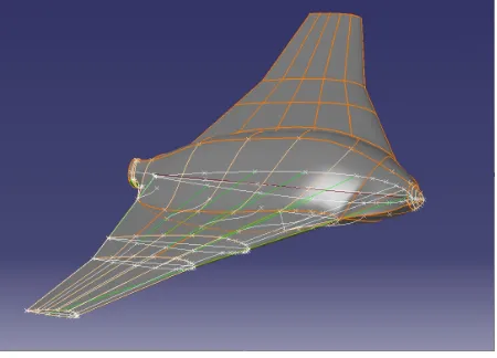
To achieve this, we have built the model on a wireframe comprising a centrebody and a wing, where the former can be stretched in all three directions to form either fore- and aft fuselages or various blended wing-body configurations (see Figure 1). Similarly, the wing has a sufficient number of degrees of freedom to accommodate concepts ranging from long endurance-type, high aspect ratio wings to short, highly loaded delta wings. Figure 2 illustrates the versatility of the CAD model.
Fig. 1 The parametric geometry is based on this wireframe – note the concertina-type nose
and tail constructions that allow extension to form a fuselage.
The design variables (81 in total) have been chosen, wherever possible, to follow engineering rather than mathematical thinking, i.e., to a large extent they are made up of parameters such as sweep, chord length, etc., rather than just spline knot coordinates.
Let us now look at the issues involved in populating the space enclosed by the external surface with an internal structure. Broadly speaking, there are two possible approaches here. The first is to augment the set of external envelope variables with additional, often discreet, variables to describe frame, spar and rib numbers, locations, shapes and sizes. The main drawback of such a geometry is that any optimization study based on it is likely to suffer from the ‘curse of dimensionality’. If a design space is to be filled uniformly (and conceptual design systems are often called upon to perform such an exercise), the number of designs that need to be considered increases exponentially as the number of design variables goes up. In other words, additional degrees of freedom may impair our ability to conduct effective searches – this prompted us to look at alternatives.
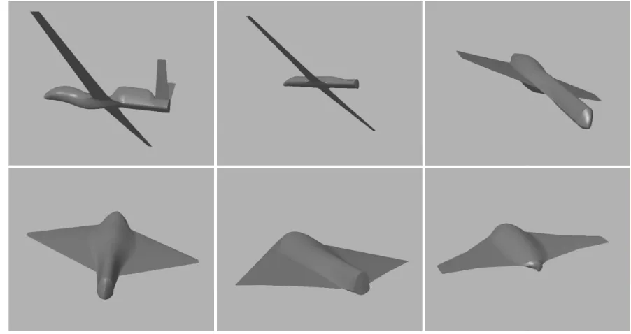
[image:3.596.195.420.262.424.2]Fig. 2 A selection of geometries generated by the geometry service, including a clone of the
Global Hawk (top left), morphing into an X-47 clone (bottom centre).
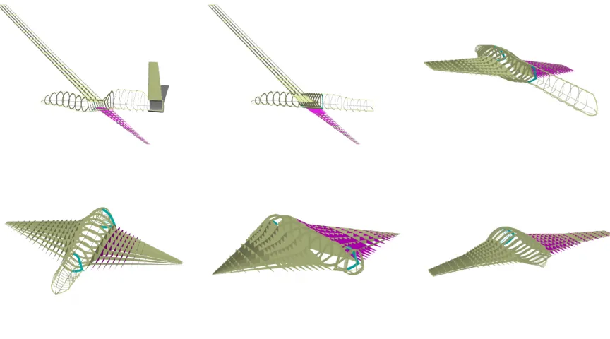
the external envelope and adapts to its changes. Depending on the results of subsequent analyses as well as on the space requirements of the various systems of the aircraft, unnecessary entities can be removed, thus allowing the designer to ‘sculpt’ the desired topology. Of course, any geometry will be a subset of the pre-defined structural universe – other requirements can be implemented manually later, at the preliminary design stage. Figure 3 depicts the structural universe as it changes to conform to the external shapes shown in Figure 2.
Modularity
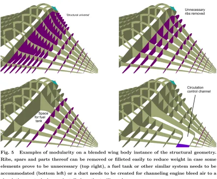
A prerequisite of the structural universe approach is modularity, that is, the guarantee that that almost any logical sub-element of the geometry is (or can easily be turned into) a separate entity. Such elements can then be removed from the design, without compromising its suitability for any subsequent (usually automated) analysis. Figures 4 and 5 illustrate this feature for a number of examples. For example, it is very easy to create space for various systems that have to be accommodated inside the airframe, such as radars, fuel tanks or circulation control channels. Most important, however, is the possibility of removing elements that are ‘not earning their keep’, that is, have been judged to be under-utilized by, say, an automated stress analysis process.
[image:4.596.80.531.93.332.2]Fig. 3 A selection of internal structure models generated by the geometry service of the UAV
conceptual design system, corresponding to the external surface geometry sequence shown in
Figure 2.
Fig. 4 In this hypothetical example parts of some fuselage frames had to be removed to create
space for a radar. Due to the modular nature of the structural model, this type of alteration
can be performed easily in the early stages of the conceptual design process.
III. Sizing the Initial Concept
[image:5.596.93.525.98.338.2] [image:5.596.86.530.408.555.2]Fig. 5 Examples of modularity on a blended wing body instance of the structural geometry.
Ribs, spars and parts thereof can be removed or filleted easily to reduce weight in case some
elements prove to be unnecessary (top right), a fuel tank or other similar system needs to be
accommodated (bottom left) or a duct needs to be created for channeling engine bleed air to a
circulation control plenum installed on the trailing edge.
The prerequisite of the initial weight estimate is an estimate of the empty weight fraction – this is generally obtained from statistical data. However, it is well known that the empty weight fraction shows significant variation between classes of aircraft. For example, while the empty weight of a flying boat is typically around 70% of its maximum takeoff weight, this figure is often as low as 40% in the case of a military transporter or heavy bomber. The difficulty from the UAV designer’s perspective is that the established textbooks often do not provide separate empty weight fraction charts for UAVs. This is mostly a consequence of the data sparsity discussed earlier – Figure 6 is the result of our attempt at capturing some of the currently available takeoff weight (W0) and empty weight (We) data
into a power law relationship between takeoff weight and empty weight fraction. The curve labeled ‘UAVs’ represents a regression fit through the relevant parameters of 30 UAVs currently in service, obtained from Ref 6. This law, together with standard estimates of mission segment weight fractions, fuel weight fraction and required payload capacity can then be used to compute an initial iterate of takeoff weight∗ (for details on how to do this see, e.g., Raymer’s classic text3).
∗
We note here that the empty weight fraction usually considered at this stage of the design process is the ratio of
[image:6.596.85.527.94.460.2]102 103 0.5 0.52 0.54 0.56 0.58 0.6 0.62 0.64 0.66 0.68
Takeoff weight [kg]
E m p ty w e ig h t fr a c ti o n W e / W 0 [ ] UAVs Powered sailplanes Sailplanes GA singles
Fig. 6 The power lawWe/W0= 0.916W
−0.0795
0 , represented by the dotted line, is the result of a
regression fit through the relevant parameters of 30 UAVs. Also shown are, reproduced from
Ref. 3, the empty weight fraction curves of sailplanes, powered sailplanes and single engine
General Aviation planes.
Another UAV conceptual design step that is usually not found (or at least not at this early stage) in manned aircraft design procedures is the periodical assessment of thecertifiability of the aircraft. The position of the UK Civil Aviation Authority on UAV airworthiness standards is summed up in Ref. 7, which establishes criteria for selecting the appropriate set of Joint Airworthiness Requirements (JAR) to be used for certifying a UAV. The algorithm described in Ref. 7 is based on the kinetic energy of the aircraft in two impact scenarios: unpremeditated descent and loss of control. Essentially, the stalling speed, the maximum operating speed and the maximum takeoff weight of the UAV are used as inputs and the certification algorithm based on these should be repeated regularly throughout the design process with the available best estimates of these figures, as shifting to a more demanding certification bracket (say, from JAR-VLA to JAR-23) will almost certainly have major cost implications.
The choice of a propulsion unit, another early step in the design process, also poses different trade-offs in UAV design. The increased breadth of the design space, as discussed earlier, appears here at the level of engine class choice. While it is accepted that engines of most manned aircraft will have very few engine changes throughout their lifespan, a trade-off often occurs in UAV design between short lifespan low maintenance (or no maintenance) engines and long lifespan engines, which require regular servicing.
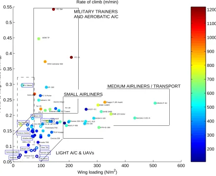
The performance of any aircraft depends on the combination of two factors: thrust to weight (or power to weight) ratio and wing loading. Figure 7, a three variable plot of climb rate versus power to weight ratio and wing loading for various propeller-driven aircraft, illustrates why the choice of these
[image:7.596.170.424.109.304.2]parameters is, again, a more difficult proposition in the UAV world. Manned aircraft clearly divide into groups, according to their roles. As the scatter plot shows, the high power to weight ratio and low wing loading area belongs to highly maneuverable aerobatic aircraft and military trainers. Medium-sized airliners and transport planes have highly loaded wings and relatively low power to weight ratios. The medium wing loading and low power to weight ratio section of the plot is the domain of small airliners. Finally, light aircraft fall into the lower left-hand corner, generally scattered around the diagonal†.
0 100 200 300 400 500 600
0.05 0.1 0.15 0.2 0.25 0.3 0.35 0.4 0.45 0.5 0.55
Embraer EMB 312 Tucano
DASH 8−100 Dornier 228−212 Extra 300 ATR 42−300 Cessna 208 ORION P−3C Hercules C130−H Su−29 SAAB 340B PC−21 PC−6 Porter PC−7 Jabiru LSA EMB−120ER Let L−610 Valmet L−90
Reims F 406 Socata TB9
RFB Fantrainer 800
Stemme S10
CN−235
EMB 123 Vector Partenavia P68
Piaggio P.180 Avanti An−28 PZL M−18T101−V T201 AIST T−411 AIST−2 T610 Voyage Aeroric Dingo SA227−CC PC−9M SF−260 M290 TP
Wing loading (N/m2)
P o w e r to w e ig h t ra ti o (k W /k g )
Rate of climb (m/min)
Predator B−001 IAI Heron Kentron Seeker Shadow 600 Shadow 200 Gnat 750 Seascan
Aerosonde Mk2 Hermes 450 Mirach 26 NRL Dakota NG Star−Bird 200 300 400 500 600 700 800 900 1000 1100 1200 SMALL AIRLINERS
MEDIUM AIRLINERS / TRANSPORT MILITARY TRAINERS
AND AEROBATIC A/C
LIGHT A/C & UAVs
Fig. 7 Scatter plot of power to weight ratio versus wing loading of a number of manned and
unmanned aircraft. The colors of the discs (manned aircraft) and annuli (UAVs) represents the
rate of climb of the aircraft, as per the color bar shown on the right. For a clearer differentiation,
the names of unmanned aircraft are framed.
Such clear role-delimitation is yet to be seen in the case of UAVs and this may make the choice of their parameters (or their sanity check, if other methods are used to choose them) slightly more difficult. Most UAVs fall in the light aircraft area of Figure 7, although, again, due to the limited
[image:8.596.96.535.211.569.2]amount of reliable data, it is not clear whether their scatter is showing the beginnings of a ‘speciation’ similar to that of manned aircraft (as suggested by the tentative dashed outlines).
IV. The Bigger Picture and Conclusions
Commercial CAD engines are increasingly popular as foundation stones for multidisciplinary con-ceptual design systems. The geometry service presented here is based on such an off-the-shelf CAD tool and can serve as a standalone concept generator loosely integrated with other design tools or as part of a tightly coupled multidisciplinary optimization system. In whichever role the reader wishes to consider implementing such a geometry generator, the central thesis of the paper remains valid: a parametric CAD engine can offer the morphological and topological freedom demanded by the highly
global nature of a conceptual design search process.
Of course, building such a model is not a trivial exercise, mainly because increases in flexibility inevitably have an impact on robustness. In other words, more degrees of freedom and wider design variable ranges usually equate to a higher percentage of nonsensical designs. Therefore, a balance needs to be struck between building a geometry that will only allow a limited scope in terms of design search space and a model that can be morphed into any imaginable shape, but will, for most variable combinations, return shapes that do not make geometrical or physical sense. One way to tackle this difficult trade-off is to attach an Expert System to the geometry service, that can store implicit and explicit knowledge on what variable combinations are likely to lead to ‘unhealthy’ geometries. Once trained, the ES can deploy this knowledge in the form of a classifier gate that prevents bad designs from entering the geometry building and analysis process. Such failed designs can simply be thrown away (many optimization algorithms can cope with evaluation failures) or can be repaired using the same ES. For a more detailed discussion on how to implement such a classifier system, the interested reader may wish to consult Ref. 8.
A ‘dimensionless’ CAD model is merely an electronic equivalent of a conceptual sketch, only containing shape and layout information. Before the iterative conceptual design process can be started, this ‘sketch’ has to be dimensioned to provide a starting point and there is ample information in the aircraft design literature on how to do this. Our observations pertaining to this process are merely notes on how to apply existing design algorithms to UAV problems. They are simply meant to be pointers towards areas that, in our view, require further research in the future.
Acknowledgements
References
1Torenbeek, E.,Synthesis of Subsonic Airplane Design, Kluwer Academic Publishers, Dordrecht, 1982.
2Stinton, D.,The Design of the Aeroplane, Collins Professional and Technical Books, 1985.
3Raymer, D. P.,Aircraft Design: a Conceptual Approach, AIAA Education Series, American Institute of
Aeronau-tics and AstronauAeronau-tics, Washington DC, 3rd ed., 1999.
4Samareh, J. A., “Survey of Shape Parameterization Techniques for High-Fidelity Multidisciplinary Shape
Opti-mization,”AIAA Journal, Vol. 39, No. 5, 2001, pp. 877–883.
5Keane, A. J. and Nair, P. B., Computational Approaches to Aerospace Design: the pursuit of excellence, John
Wiley & Sons., 2005.
6Munson, K.,Jane’s Unmanned Aerial Vehicles and Targets, Jane’s Information Group, 2002.
7Haddon, D. R. and Whittaker, C. J., “Aircraft Airworthiness Certification Standards for Civil UAVs,”CAA paper,
available online at www.caa.co.uk/docs/393/srg acp 00016-01-120203.pdf, accessed August 2005, 2002, pp. 15.
8S´obester, A. and Keane, A. J., “Classifier Systems Can Reduce Conceptual Design Time,” 1st International