UNIVERSITI TEKNIKAL MALAYSIA MELAKA
ENHANCEMENT THE PERFORMANCE OF AIR HANDLING
UNIT USING HYDRONIC HEATING SYSTEM
This report is submitted in accordance with the requirement of the Universiti Teknikal Malaysia Melaka (UTeM) for the Bachelor of Mechanical Engineering
Technology (Refrigeration and Air Conditioning System) with Honours.
by
MOHAMAD RIDZUAN BIN PAWANTEH B071310356
910904-07-5375
UNIVERSITI TEKNIKAL MALAYSIA MELAKA
BORANG PENGESAHAN STATUS LAPORAN PROJEK SARJANA MUDA
TAJUK: ENHANCEMENT THE PERFORMANCE OF AIR HANDLING UNIT USING HYDRONIC HEATING SYSTEM
SESI PENGAJIAN: 2016/17 Semester 1
Saya MOHAMAD RIDZUAN BIN PAWANTEH
mengaku membenarkan Laporan PSM ini disimpan di Perpustakaan Universiti Teknikal Malaysia Melaka (UTeM) dengan syarat-syarat kegunaan seperti berikut: 1. Laporan PSM adalah hak milik Universiti Teknikal Malaysia Melaka dan penulis. 2. Perpustakaan Universiti Teknikal Malaysia Melaka dibenarkan membuat salinan
untuk tujuan pengajian sahaja dengan izin penulis.
3. Perpustakaan dibenarkan membuat salinan laporan PSM ini sebagai bahan pertukaran antara institusi pengajian tinggi.
4. **Sila tandakan ( )
SULIT
TERHAD
TIDAK TERHAD
(Mengandungi maklumat yang berdarjah keselamatan atau kepentingan Malaysia sebagaimana yang termaktub dalam AKTA RAHSIA RASMI 1972)
(Mengandungi maklumat TERHAD yang telah ditentukan oleh organisasi/badan di mana penyelidikan dijalankan)
Alamat Tetap: NO. 28-05-15
Jalan Sungai, 10150 Georgetown Pulau Pinang
Tarikh: ________________________
Disahkan oleh:
Cop Rasmi:
iv
DECLARATION
I hereby, declared this report entitled “Enhancement The Performance of Air Handling Unit Using Hydronic Heating System” is the result of my own research
except as cited in references.
Signature :………
v
APPROVAL
This report is submitted to the Faculty of Engineering Technology of UTeM as a partial fulfillment of the requirements for the degree of Bachelor of Engineering Technology (Refrigeration and Air-Conditioning System) (Hons.). The member of the supervisory is as follow:
……….
vi
ABSTRAK
Mengekalkan tahap keselesaan haba adalah satu isu yang penting bagi manusia. Rasa ketidakselesaan akan berlaku jika suhu yang terlalu panas atau terlalu sejuk. Dalam era ini, sistem pemanasan adalah keperluan penting untuk penyejukan berlaku. Kebanyakan penghawa dingin sedia ada di pasaran yang menggunakan pemampatan wap kitaran berbanding serapan kitaran. Dalam kes itu, ia memerlukan penggunaan tenaga tinggi yang beroperasi. Dandang adalah tujuan khas dengan menggunakan Pemanas air. Sistem tangki mengagihkan haba dalam air panas dengan pam, sehingga air panas melalui pemanas gegelung atau peranti lain dan menghantar ke ruang panas yang diperlukan. Air sejuk akan kembali ke dalam tangki untuk dipanaskan semula. Sistem air panas sering dipanggil sistem hidronik. Selain itu, kipas dan salur sistem, dandang yang menggunakan pam untuk mengedarkan air panas melalui paip ke unit atau bekas udara. Tujuan kajian ini adalah untuk menentukan optimum parameter sistem hibrid pemanas, melalui suhu dan bolong kawasan yang mempunyai keadaan keselesaan haba. Oleh kerana kitar pemampatan wap tersebut tidak digunakan untuk menyerap dan mengalih keluar udara sejuk dari ruang yang memerlukan haba. Oleh itu, keadaan ini boleh dianggap sebangai mesra alam seperti sumber air digunakan untuk pelepasan. Kerja-kerja eksperimen dilakukan untuk membandingkan suhu sebelum dan selepas pemasangan dan pelaksanaan sistem pemanas hidronik. Sistem ini adalah bergantung kepada iklim di luar kawasan sekitar, jika suhu luar - 5⁰c suhu di dalam kawasan bilik memerlukan suhu yang lebih tinggi dalam anggaran 30⁰c supaya ruang bilik mendapatkan keselesaan yang diingini.
vii
ABSTRACT
viii
DEDICATIONS
ix
ACKNOWLEDGMENTS
x
TABLE OF CONTENT
DECLARATION iv
APPROVAL v
ABSTRAK vi
ABSTRACT vii
DEDICATION viii ACKNOWLEDGMENTS ix
TABLE OF CONTENTS x
LIST OF TABLE xiv LIST OF FIGURE xv
LIST OF ABBREVIATIONS, SYMBOLS AND NOMENCLATURE xvii
CHAPTER 1: INTRODUCTION 1 1.0 Background of study 1
1.1 Problem statement 2
1.2 Objective 2
1.3 Scope Project 2
1.4 Organization of the thesis 3
CHAPTER 2: LITERATURE REVIEW 4 2.0 Introduction 4
2.1 Background HVAC System 4
xi
2.2.1 Principles of Refrigeration 6
2.3 Air Handling Unit (AHU) 7
2.3.1 Location 7
2.3.1.1 Steam pre-heat coil 8
2.3.1.2 Placement of coil 9
2.3.1.3 Cooling coil face velocity 9
2.3.2 Performances 9
2.3.3 Coil placement inside AHU 10
2.3.4 Application in handling unit 10
2.4 Thermal Comfort 10
2.4.1 Standard value for thermal comfort 12
2.5 Hydronic heating system 12
2.5.1 Definition 12
2.5.2 History of hydronic radiant heating system 13
2.5.3 Variable heating system 14
2.5.4 Energy consumption of hydronic radiant heating system 14
2.5.5 Comparison between hydronic radiant heating system and air-cond 15
2.6 Copper pipe 15
2.6.1 Type 15
2.6.2 Advantages 16
2.7 Heat transfer and thermal conductivity 16
xii
CHAPTER 3: METHODOLOGY 19
3.0 Introduction 19
3.1 Research flowchart 19
3.2 Design and dimension 21
3.3 Fabrication process 22
3.3.1 Material and component 22 3.3.2 Selection of equipment 30 3.3.3 Preparation body of chamber 32
3.3.4 Apparatus and material assembly 33
3.4 Fabrication procedures 34
3.5 Experimental process 43
3.5.1 First experimental setup (Water temperature) 43
3.5.2 Second experiment 44
3.5.3 Third experiment 46
3.5.4 Experimental equipment 46
3.5.4.1 Tank water 49
3.5.4.2 Distance of coil 49
3.5.4.3 Number of coil 49
3.6 Flowchart of experiment 50
CHAPTER 4: RESULT & DISCUSSION 52
4.0 Introduction 52
4.1 Experiment 1 52
xiii
4.2.1 Case 1(a) 55
4.2.2 Case 1(b) 56
4.2.3 Case 2 57
4.2.4 Case 3 58
4.3 Experiment 3 60
4.3.1 Case 1(a) 60
4.3.2 Case 1(b) 61
4.3.3 Case 2 62
4.3.4 Case 3 64
CHAPTER 5: CONCLUSION & RECOMMENDATION 65
5.0 Introduction 65
5.1 Summary of research 65
5.2 Achievement of research objective 65
5.2.1 To fabricate hydronic heating system chamber for heating case 66
5.2.2 To investigate the posibility of hydronic heating 66
5.2.3 To examine multiple coil effect in hydronic system for heating case 66
5.3 Significant of research 67
5.4 Problem faced during research 67
5.5 Suggestion for future work 67
APPENDIX 69
xiv
LIST OF TABLE
2. 1 Personal factor that determine the level of thermal comfort 11
2.2 Standard value ISO 7730,1995 12
2.3 Type and function of copper pipe 16
3.1 Name of equipment by it function and diagram 31 3.2 Work progress with it detail and diagram 34
3.3 Time of water to be heated 44
3.4 Three case were oduct with different distance between fan 45 3.5 Two cases were conduct by different number of coil 46
4.1 Time taken of water to be heated with amount sodium chloride 53
4.2 Data collecting on experiment 2 54
xv
LIST OF FIGURE
2.1 Refrigerant cycle 6 2.2 Air handling unit flow 8
2.3 Typical heating system 14
3.1 Research Flowchart 20
3.2 3Draft drawing for chamber body 21
3.3 Isometric draft drawing for the system 22
3.4 Acrylic sheet 23
3.5 Copper pipe 23
3.6 Insulator type 24
3.7 Water immersion heater with plug 24
3.8 Axial fan 25
3.9 Proton waja (heating coil) 25
3.10 AC water pump 26
3.11 Hollow metal 26
3.12 Silica gel 27
3.13 Tank 27
3.14 Thread steel 27
3.15 Plywood 28
3.16 Screw and nut 28
3.17 Bracket steel 28
3.18 PVC pipe 29
3.19 Electrical box 29
3.20 Fan regulator 30
3.21 Zinc sheet 30
3.22 Channel by acrylic sheet 33
3.23(a) Heating coil assembly 34
xvi
3.23(c) Assembly process 35
3.23(d) Cutting thread metal process 35
3.23(e) Completed assembly 35
3.23(f) Cutting hollow metal process 36
3.23(g) Dimension for bracket 36
3.23(h) Eliminate burs using grinding 36 3.23(i) Painted the frame of chamber 37
3.23(j) Measure and mark process 37
3.23(k) Eliminate burr using round file 38
3.23(l) Attach clip for door 38
3.23(m) Drill process 38
3.23(n) Acrylic completed assemble 39
3.23(o) Assemble fan at L bracket 39
3.23(p) Regulator installation 39
3.23(q) Hole on rubber 40
3.23(r) Make an hole at metal plate to insert copper joint 40
3.23(s) Drill hole on acrylic 40
3.23(t) Complete the hole 41
3.23(u) Tied the PVC pipe 41
3.23(v) Cutting process for drain pan 41
3.23(w) Completed drain pan 41
3.23(x) Connect pipe PVC 42
3.23(y) Flare copper pipe 42
3.23(z) Connect copper pipe to suction and disharge of heating coil 42
3.24 Completed System 43
3.24(a) Distance 0.3 m 45
3.24(b) Distance 0.5 m 45
3.24(c) Distance 0.7 m 45
3.24(d) Two rows of heating coil 46
3.24(e) Three rows of heating coil 46
3.25 Thermometer Fluke 47
3.26 Anemometer 48
xvii
3.28 Experimental flowchart 51
4.1 Temperature againts time in minute 53
4.2 Air temperature againts distance heating coil and mode of fan 55 4.3 Temperature againts distance of cooling coil and mode of fan 56 4.4 Air velocity againts distance between fan and mode of fan 57 4.5 Air flow rate againts distance of fan with it modes 59 4.6 Air temperature inlet againts number of heating coil 61 4.7 Air temperature againts number of heating coil 62 4.8 Air flow rate againts number of heating coil 63
xviii
LIST OF ABBREVIATIONS, SYMBOLS AND
NOMENCLATURE
HRC - Hydronic Radiant Heating
HVAC - Heating, Ventilating and Air-conditioning
A - Area
h - Height
m - Mass
̇ - Mass Flow Rate
P - Pressure
R - Radius
- Temperature
- Difference in temperature
W - Weight
- Stefan BoltzmannConstant Tmr - Mean radiant temperature
AN - Area of surface
Tmr - Mean radiant temperature
1
CHAPTER 1
INTRODUCTION
In this chapter introduction is the most important topics which contain some subtopics which are briefing background of the study, problem statement, objectives, scope and organization of the thesis.
1.0 Background of study
Central system is an air conditioning system which uses a series of equipments to distribute heating media to exchange cool and supply conditioned air into space (Siddharth,2013). It commonly uses water and refrigerant as a heating media for a small building. This process involves the application of chiller, air handling unit and cooling tower. Air handling unit (AHU) is a important device in a central system and it is used to re-condition and circulate air as part of a heating, ventilating, and air-conditioning (HVAC) system. Usually a large metal box containing a blower, heating coil, filter, drain pan, and dampers. Air handler normally is connected to a duct system to distribute the condition air into space (Yin Yan,2014).
2
heat. The system also does not require high energy consumption and the cost of material is low.
1.1 Problem statement
In overcome the excessive cooling climate area to distribute heating air that led many building by use air conditioning in getting comfort temperature. The total energy consumption will increase and cause a large impact on economy (Chan & Qin,2011). Most of the existing air-conditioning in the market using vapour compression cycle compared to absorption cycle. Compressor is one of the basic components in the vapor compression cycle and it is assigned to compress the refrigerant into the system. In case of that, vapor compression cycle use a refrigerants as a medium transportation which absorb and remove heat from a space to be heated. These can be less environmental friendly as they require refrigerants for emission. The study is looking for possibility source of heating associate with air handling unit (AHU) with less energy consumption to be assigned by using heating hydronic system.
1.2 Objective
a) To fabricate hydronic heating system chamber for heating case experiment.
b) To investigate the possibility of hydronic heating in hydronic chamber.
c) To examine multiple coil effect in hydronic system for heating case.
1.3 Scope Project
3
the tool facilities to build the project is comprehensive. By narrowing the needs for this project, a few guidelines are proposed to ensure that this project will achieve it objective. The scope covered for this project are to design chamber that includes coils location and it distance between fan and to study the suitable distance with number of coils. In addition, heater capacity is considered to get desired temperature on water tank.
1.4 Organization of the thesis
4
CHAPTER 2
LITERATURE REVIEW
2.0 Introduction
In this chapter, the basic knowledge of system air-conditioning and air handling unit (AHU) will be discussed. Firstly the theory will be introduced. Next will discuss and review a previous project that had applied hydroning heating system concept and theory.
2.1 Background HVAC System
5
2.2 Air Conditioning
6
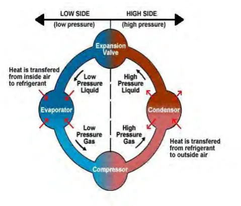
[image:23.595.206.446.146.351.2]2.2.1 Principles of Refrigeration
Figure 2.1 Refrigeration cycle
(Air Conditioning Basic Refrigeration Cycle,2016)
a) Liquids absorb heat when changed from liquid to gas
b) Gases give off heat when changed from gas to liquid.
c) For an air conditioning system to operate with economy, the refrigerant must be used repeatedly. For this reason, all air conditioners use the same cycle of compression, condensation, expansion, and evaporation in a closed circuit. The same refrigerant is used to move the heat from one area, to cool this area, and to expel this heat in another area.
7
f) The liquid then moves to the expansion valve under high pressure. This valve restricts the flow of the fluid, and lowers its pressure as it leaves the expansion valve.
g) The low-pressure liquid then moves to the evaporator, where heat from the inside air is absorbed and changes it from a liquid to a gas.
h) As a hot low-pressure gas, the refrigerant moves to the compressor where the entire cycle is repeated.
Note that the four-part cycle is divided at the center into a high side and a low side This refers to the pressures of the refrigerant in each side of the system (Air Conditioning-Basic Refrigeration, 2016).
2.3 Air Handling Unit (AHU)
According from Norris and sreenivas members of 1997, a typical air handling unit (AHU) in a heating, ventilation, and air-conditioning (HVAC) system consists of an outside-air, return-air and exhaust-air damper. Air from the outside is drawn into a HVAC system via the outside-air damper. This air is usually mixed with recycled air and circulated to the rooms in a building. A portion of the net volume flow out of the rooms is exhausted, while the remainder is recycled, The quantity of outside-, exhaust- and recycled-air is modified by appropriate changes to the outside-, exhaustand return-air damper angles. The duct work in an HVAC system is equipped with a supply-fan. The speed of the supply-fan is determined by the current thermal load of the HVAC system, and is therefore not constant. In the absence of any control, varying speeds of the fan will result in different volume flows of outside air into the system.
2.3.1 Location