International Journal of Innovative Technology and Exploring Engineering (IJITEE) ISSN: 2278-3075, Volume-8 Issue-8 June, 2019
Abstract: CFS sections are used widely as structural elements throughout the world. These sections are thin walled elements which are capable of replacing hot rolled sections. Out of the common sectional configurations can be produced economically by cold formed operations, and therefore promising strength to weight ratio can be obtained. This paper presents the study of buckling behaviour of cold formed steel columns. The specimen dimensions were framed according to Indian Standard Codes IS: 801-1975 and Channel section specifications under Indian Standard Codes IS: 811-1987. Finite element method is used to analyse the buckling of steel columns. Total number of eight different channel sections were analysed using finite element method. Experimental tests were carried out under compression loading and various failure modes are analysed. Three different sections which are found effective are analysed physically using experimental tests. Conclusively experimental results are compared with finite element analysis results. Examining the results, the section FF200-S0-C20- 3 takes up higher load carrying capacity of about 1.73 times than the basic back-to-back channel section. Local buckling is the sort of failure achieved when the segment gets pass the ultimate strength.
Keywords: Cold Formed Steel, Compression, Buckling behaviour, Channel sections
I. INTRODUCTION A. General
Cold formed steel (CFS) individuals are winding up progressively mainstream in construction industry because of their high strength to weight ratio. Fabrication of the cold formed steel components are simple contrasted with hot rolled steel. These elements provide a wide range of application when subjected to axial compression loads. Thickness is a lot slender than that of hot-rolled steel section. These slender walled members can be liable to different sorts of buckling modes, including flexural torsional buckling. Cold formed steel structural elements have been customarily utilized as secondary load carrying individuals in a wide scope of utilizations, for example roof purlins, wall girts, stud walls
Revised Manuscript Received on June 05, 2019
Praveen Kumar S,M.E. in Structural Engineering from SRM Valliammai Engineering College, Kattankulathur, Tamil Nadu, India
Suresh Babu S, Assistant Professor, Department of Civil Engineering, SRM Valliammai Engineering College, Kattankulathur, Tamil Nadu, India SenthilSelvan S, Professor, Department of Civil Engineering, SRM Institute of Engineering and Technology, Kattankulathur, Tamil Nadu, India.
and cladding. In this paper, the results of eight new numerical tests on back-to-back and face-to-face built-up cold formed steel section, with the sections acting as columns. These eight different sections have been built-up in different ways and one of a kind. Gapped sections are being introduced with bolted connection in steel trusses and columns in portal frames, increasing the lateral stability of such columns. Analysing the results, three different sections are being chosen for which the ultimate strength is higher compared with the rest of the sections.
In the literature, the research reported by Ben Young [1] in 2008, concentrated on cold-formed steel open sections, for example, plain and lipped channels, channels with simple and complex edge stiffeners just as plain and lipped angles, and unequal angles. Both experimental and numerical examinations concerning the strength and conduct of cold formed steel columns were led. The column strengths got from these examinations were contrasted and the design strengths acquired utilizing different international standards for cold-formed steel structures.
Krishanu et al. [2] in 2018, presented forty experimental investigations on back-to-back gapped built-up cold formed steel channel sections which works as columns, where the gaps are linked using stiffeners bolted between the webs.
Yan Lu et al. [3] in 2017 reported a total of 18 single C-section columns and 18 built-up I-section columns which were tested experimentally under uniaxial compression load. Jun Ye et al. [4] in the year 2017 carried out 36 axial compression tests on CFS channel with three different lengths (1m, 1.5m, 2m) and four various sections were tested under concentrically applied load and pin-ended boundary conditions. This study was carried on to study the interaction of local and overall flexural buckling in CFS plain and lipped channel sections.
Helder D. Craveiro et al. [5] in 2016 presented an experimental study on buckling behaviour of compressed single and built-up cold formed steel columns. Four types of cross sections were tested, one single, one open built-up and two closed built-up under two end-support conditions, pin-ended and fix-ended condition.
B. Section labelling
Experimental Study on Compressive Behaviour
of Cold Formed Steel Sections With and Without
Bent Lips
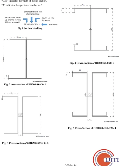
The sections were labelled such that the type of section, gap between two channel sections, width of lip and specimen number were indicated by the label. As shown in fig. 1, the label “BB200-S0-C20- 3” are explained as follows:
“BB200” indicates back-to-back built-up channels with 200mm web depth.
“S0” indicates the distance between two channel sections
“C20” indicates the width of the lip section. “3” indicates the specimen number as 3.
[image:2.595.71.531.173.812.2]Fig.1 Section labelling
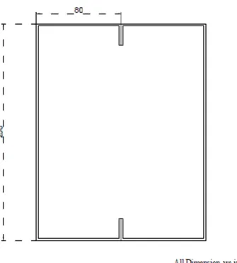
Fig. 2 cross-section of BB200-S0-C0- 1
Fig. 3 Cross-section of GBB200-S25-C0- 2
C. Specimen geometry
[image:2.595.328.517.436.642.2]This paper presents the comparative study of eight different cold formed steel (CFS) sections by performing numerical analysis and experimental analysis. Indian Standard codal provisions IS 811: 1987 Cold Formed Light Gauge Structural Steel Section recommends various sections which can be used as structural members. Fig. 2-9 shows the cross-section details of different sections which are being currently used in this paper.
Fig. 4 Cross-Section of BB200-S0-C20- 3
[image:2.595.77.255.527.701.2]International Journal of Innovative Technology and Exploring Engineering (IJITEE) ISSN: 2278-3075, Volume-8 Issue-8 June, 2019
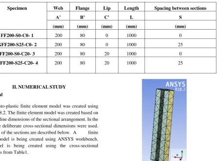
Fig. 6 Cross-Section of FF200-S0-C0- 1
[image:3.595.338.506.71.257.2]Fig. 7 Cross-Section of GFF200-S25-C0- 2
[image:3.595.69.247.72.258.2]Fig. 8 Cross-Section of FF200-S0-C20- 3 Fig. 8 cross-section of FF200-S0-C20- 3
[image:3.595.63.546.600.819.2]Fig. 9 Cross-Section of GFF200-S25-C20- 4
Table 1
a) Measured specimen dimensions for built-up back-to-back channel sections
Specimen Web Flange Lip Length Spacing between sections
A’ B’ C’ L S
(mm) (mm) (mm) (mm) (mm)
BB200-S0-C0- 1 200 80 0 1000 0
GBB200-S25-C0- 2 200 80 0 1000 25
BB200-S0-C20- 3 200 80 20 1000 0
b) Measured specimen dimensions for built-up face-to-face channel sections
Specimen Web Flange Lip Length Spacing between sections
A’ B’ C’ L S
(mm) (mm) (mm) (mm) (mm)
FF200-S0-C0- 1 200 80 0 1000 0
GFF200-S25-C0- 2 200 80 0 1000 25
FF200-S0-C20- 3 200 80 20 1000 0
GFF200-S25-C20- 4 200 80 20 1000 25
II.NUMERICALSTUDY A. General
An Elasto-plastic finite element model was created using ANSYS 18.2. The finite element model was created based on the centre line dimensions of the sectional arrangement. In the model, the deliberate cross-sectional dimensions were used. Modelling of the sections are described below. A finite element model is being created using ANSYS workbench. The model is being created using the cross-sectional dimensions from Table1.
B. Analysis procedure
The complete geometry was modelled for all the different sections as described earlier. The link between two specimens or sections are provided using bonded connections. Gapped sections are linked one another using bolted connections. Uniaxial load was applied on to the specimen through its Centre of Gravity (CG). The columns were loaded from the top and checked for its compressive behaviour.
C. Geometry & Material modelling
ANSYS 18.2 analysis software is being used to model the whole geometry of the built-up columns. The Yield strength of the material is 280MPa and tensile strength is 410Mpa which are derived from Indian Standards IS 513: 2008 Cold Reduced Low Carbon Steel Sheets and Strips [8].
D. Finite element mesh
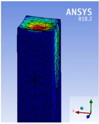
[image:4.595.88.535.77.408.2]The channel sections and the linked sections are being modelled using Ansys workbench 18.2 where finite element analysis is being carried out by adding fine mesh throughout the specimen. The method used to add mesh is tetrahedrons mesh. The element size of the mesh is 0.1m. The whole specimen is being split into fine portions and thereby increases accuracy. A typical finite mesh is shown in Fig. 10.
Fig. 10. Typical finite element mesh (BB200-S0-C0- 1) E. Boundary condition and application of load
The support conditions for the contrary cold formed steel sections were rested on simply supported condition. Uniaxial load is being applied on to the specimens through its Centre of Gravity (CG). Fig.11 shows the typical boundary condition and application of load.
[image:4.595.369.483.544.705.2]International Journal of Innovative Technology and Exploring Engineering (IJITEE) ISSN: 2278-3075, Volume-8 Issue-8 June, 2019
F. Analytical result
This section provides the results of total number of 8 different specimens which are checked analytically using Ansys workbench 18.2 software. The results show that the failure pattern of 8 contrary sections which are one of its kind. The analytical results show that the specimens BB200-S0-C20- 3, GBB200-S25-C20- 4, FF200-S0-C20- 3 provides better structural stability and load carrying capacity compared with the rest of the specimens. Fig.12 shows the typical results for total deformation (GBB200-S25-C20- 4). The specimens suggested above are recommended for experimental analysis to check the structural stability and load carrying capacity experimentally and thereby suggested for practical use as primary member.
Fig. 12. Typical results for total deformation (GBB200-S25-C20- 4)
The results of the specimen GBB200-S25-C20- 4 from the Fig.12 shows that local buckling is the kind of failure accomplished in the specimen.
[image:5.595.346.507.51.253.2]
Fig. 14. Typical results for total deformation (FF200-S0-C20- 3)
Fig. 13 shows the total deformation of the specimen BB200-S0-C20- 3. Local buckling is the failure mode acting in the specimen.
The compression of member leads to failure of the specimen as shown in fig. 14. The failure mode shows that the maximum deflection is being caused at the top end of the column. Local buckling is the type of failure occurring in the column specimen.
Table 2 shows the results for the various sections which are checked analytically using Ansys workbench 18.2. A table is prepared for the various sections tested with the maximum deformation results for the ultimate load acting in the column.
[image:5.595.95.244.271.448.2] [image:5.595.99.249.546.728.2]Table 2
a)Analytical results for built-up back-to-back channel sections
Specimen Ultimate load Deflection at Ultimate
load
Stress at Ultimate load
(KN) (mm) (N/mm2)
BB200-S0-C0- 1 126.3 1.65 120
GBB200-S25-C0- 2 113.9 4.52 346
BB200-S0-C20- 3 156.3 2.83 365
GBB200-S25-C20- 4 206.8 6.62 372
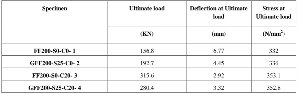
b)Analytical results for built-up face-to-face channel sections
Specimen Ultimate load Deflection at Ultimate
load
Stress at Ultimate load
(KN) (mm) (N/mm2)
FF200-S0-C0- 1 156.8 6.77 332
GFF200-S25-C0- 2 192.7 4.45 336
FF200-S0-C20- 3 315.6 2.92 353.1
GFF200-S25-C20- 4 280.4 3.32 352.8
III. EXPERIMENTAL TESTS A. Test Sections
Fig. 2-9 shows the detailed cross-sections of the different sections which are considered in this paper. Experimental tests are carried out in the laboratory for three different sections which are chosen using the results of numerical analysis for which the structural stability and load carrying capacity are higher compared with the rest of the sections. In this investigation three sections BB200-S0-C20- 3, GBB200-S25-C20- 4 and FF200-S0-C20- 3 are being tested experimentally in the laboratory. Table 1 lists the measured column dimensions. The experimental test programme comprises of 9 specimens, subdivided into three different sections with three trials each. All columns are supported using pin ended supports. In table 1, the test specimens have
been subdivided into back-to-back sections and face-to-face sections where two back-to-back sections and one face-to-face section are tested.
B. Testing Procedure
[image:6.595.84.160.634.753.2]The specimen is being placed on the testing frame of 1000 KN capacity. Two LVDT’s are placed, one is placed to the mid span of the section to measure maximum deformation and another is placed on the axis of the base plate to measure axial shortening of the column. Two strain gauges are placed, one is fixed at 250mm distance from the bottom of the section and another one is fixed to the interior mid span of the section. The column is loaded using Self Restraining jack. Uniaxial load is being applied through the jack on to the specimen and the column is being checked for its compressive behaviour. Fig. 15 shows the photographs of the specimens when placed on the testing frame.
15 (a) Test setup of the specimen (BB200-S0-C20-3)
15 (b) Test setup of the specimen (GBB200-S25-C20- 4)
International Journal of Innovative Technology and Exploring Engineering (IJITEE) ISSN: 2278-3075, Volume-8 Issue-8 June, 2019
LVDT positioning Table 3
Comparative results of different sections Specimen Experimental
Results
Finite Element
Results
Comparison Deflection at Ultimate
load
Deflection at Ultimate
load
Failure mode
PEXP PFEA PEXP/ PFEA DEXP DFEA -
(KN) (KN) - (mm) (mm) -
BB200-S0-C20- 3 190 156.3 1.21 6.6 2.83 Local
GBB200-S25-C20- 4 250 206.8 1.21 10.68 6.62 Local
FF200-S0-C20- 3 340 315.6 1.07 3.30 2.92 Local
C. Experimental results
Experimental failure loads and buckling failure modes for the test specimens are shown in Table 3. As can be seen, the section FF200-S0-C20- 3 has higher load carrying capacity and structural stability comparing with the rest of the sections. This section reaches the maximum PEXP load of about 340KN. Fig. 16 shows the buckling failure caused in the specimen when application of the Uniaxial load. The failure of the specimen is visualised near the ends of the specimen giving a conclusion that it is local buckling type of failure acting in the column.
16(a) Buckling of the specimen (BB200-S0-C20-3)
16(b) Buckling of the specimen (GBB200-S25-C20- 4)
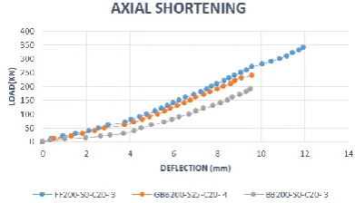
16(c) Buckling of the specimen (FF200-S0-C20- 3) IV. RESULTS & DISCUSSION A. Load Vs Deflection (Axial shortening)
[image:7.595.52.515.98.238.2]Axial shortening of the specimen is the compressive behaviour of the specimen where the specimen compresses on application of load.
Fig. 17 Load Vs Deflection (axial shortening) Fig. 17 shows the graph plotted for load vs deflection (axial shortening) where deflection is measured using LVDT placed on the axis of the base plate. B. Load vs Deflection (Buckling)
Fig.18 shows the buckling behaviour of the specimens when application of Uniaxial load. The deflection is being
measured using a LVDT placed at the mid-span of the specimen where the
[image:7.595.334.530.538.650.2] [image:7.595.129.196.574.688.2]Fig. 18 Load Vs Deflection (Buckling)
C. Load Vs Strain (Axial)
[image:8.595.69.260.54.162.2]Fig.19 shows the graph plotted for the load and the strain under axial position of the specimen. It is used to determine the material behaviour under the influence of the load.
Fig. 19 Load Vs Strain (Axial)
[image:8.595.72.258.280.395.2]D. Load Vs Strain (buckling)
Fig.20 shows the graph plotted for the uniaxial load and strain placed under the mid span.
Fig. 18 Load Vs Strain (Axial)
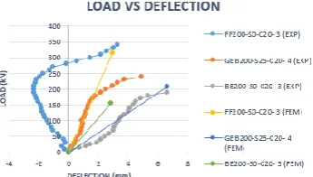
E. Numerical results Vs Experimental results
Fig.21 shows the graph plotted for the uniaxial load applied and the deflection recorded at the maximum point.
Fig. 21 Load Vs Deflection (EXP Vs FEM) V. CONCLUSIONS
An extensive investigation has been carried out on the axial strength of contrary cold formed steel built-up sections are presented in this paper. A total number of 8 different sections have been analysed for its compressive behaviour using finite element analysis (ANSYS 18.2). Examining the results of finite element analysis, 3 sections shows promising load carrying capacity and structural stability compared to remaining section. These 3 sections have been chosen for carrying out experimental investigation. A total number of 9 tests I.e. 3 different sections with 3 trials each have been checked for experimental analysis. By analysing the experimental investigation results, FF200-S0-C20- 3 section provides higher load carrying capacity with less deformation compared to the rest of the sections. This section provides about 1.78 times higher load carrying capacity than the basic back-to-back section. The results discussed are on failure modes, load-axial shortening, load- axial strain and deformed shapes during ultimate failure.
REFERENCES
1. Ben Young (2008) “Research on cold-formed steel columns” Thin walled structures 46
2. Benjamin W. Schafer, David C. Fratamico , Kim J.R. Rasmussen, Shahabeddin Torabian , Xi Zhao, , (2018) “Experiments on the global buckling and collapse of built-up cold-formed steel columns” Thin-walled structures 114
3. Dongyu Liu, Hongbo Liu, Xiangwei Liao Zhihua Chen, (2016) “Structural behavior of extreme thick-walled cold-formed square steel columns” Journal of Construction Steel Research 128 4. Hieng Ho Lau, James B.P. Lim, Krishanu Roy, Tina Chui Huon
Ting, (2018) “Nonlinear behaviour of back-to-back gapped built-up cold-formed steel channel sections under compression” Thin-walled structures 147
5. Ben Young, Ju Chen (2008) “Column tests of cold-formed steel non-symmetric lipped angle sections” Journal of Constructional Steel Research 64.
AUTHORS PROFILE
[image:8.595.60.236.505.611.2]International Journal of Innovative Technology and Exploring Engineering (IJITEE) ISSN: 2278-3075, Volume-8 Issue-8 June, 2019
Mr. Suresh Babu. S was a Prominent Assistant Professor, Department of Civil Engineering, SRM Valliammai Engineering College, Kattankulathur, Tamil Nadu, India. He has done his Bachelor's degree in Civil Engineering (2006) from K.S. Rangasamy college of Engineering, Thiruchengodu, Tamilnadu. He has done his Master’s degree in Structural Engineering (2011) from SRM University, Chennai and currently pursuing Ph.D. from SRM University.