Issue 1 | Vol. 12 (2019) Article | DOI: 10.21307/ijssis-2019-002
Low cost structured-light based 3D surface reconstruction
Yijun Yan1, Maher Assaad2,*,
Jaime Zabalza1,Jinchang Ren1,*and
Huimin Zhao3,*
1Department of Electronic and
Electrical Engineering, University of Strathclyde, Glasgow, UK.
2Department of Electrical
Engineer-ing, Ajman University, United Arab Emirates.
3School of Computer Science,
Guangdong Polytechnic Normal University, Guangzhou, China. *E-mail: [email protected]; [email protected]; [email protected] This paper was edited by Ivan Laktionov.
Received for publication January 28, 2019.
Abstract
In an increasingly specialized industry with strong demands from end users, product quality plays a key role in industrial manufacturing, where the quality impact highly depends on the final product and its application. An important parameter for quality control is the surface finish of objects, essential for determining their technical suitability. Therefore, measuring the surface levelness can be critical to ensure that the finished material meets the design specifications. In this work, we propose an effective yet low-cost solution using out-of-the-shelf components, which is based on the structured light principle for depth/3D measurements (line laser). By means of laser triangulation, this solution can provide rapid and accurate levelness measurements both in 1D profiles and 2D maps for a relatively wide range of sizes, materials and other conditions. The experimental evaluations show a satisfactory performance with a great trade-off between accuracy and cost, becoming not only a rapid but a cheap solution, making it ideal for quick inspections in diverse environments.
Keywords
Structured-light, Line-laser, 3D-surface reconstruction, Levelness, Roughness
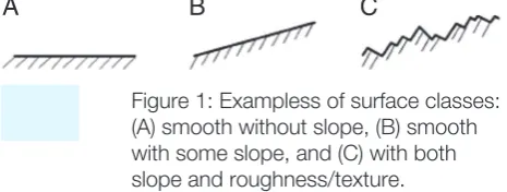
Being an important quality parameter for many dif-ferent products, the surface levelness requires close and continuous monitoring during manufacturing. Surfaces in manufactured objects can be classified into different categories, which include ideal surfaces that have neither slope nor roughness; surfaces that have some slope without roughness; and surfaces with both slope and roughness (Fig. 1). Depending on the applications and final use of a product, appropri-ate inspection of surface finish is crucial for monitoring and assessment of the surface finish quality. How-ever, levelness readings are derived from depth/3D measurements which can be a bottleneck in many industrial processes, due to the high accuracy re-quired, elevated cost, and tedious maintenance of the acquisition systems. Many depth/3D measurement techniques (Fang et al., 2017) have been explored to compute surface levelness such as time of flight (ToF)
(Hagebeuker and Marketing, 2007; Lussana et al., 2015; Wheaton et al., 2017), stereo vision (Brown et al., 2003; Sandoz et al., 2010; Zhou et al., 2018), optical fiber sensing (Mohanty and Kuang, 2011; Eznaveh et al., 2017; Wang et al., 2018), and structured light (Huang et al., 2017; Xu et al., 2017; Zhang, 2018). In general, they vary in terms of working distance, image resolution, response speed, cost, and hardware con-figuration. A brief discussion and comparison of them are given as follows.
Related work
the light speed and the traveling time of the light. In general, the ToF techniques are very stable and re-quire no calibration to produce depth/3D information of the object under test. For these reasons, they have been widely developed by many corporations such as Infineon Technologies, Texas Instruments and Mi-crosoft (MiMi-crosoft Kinect) (Sarbolandi et al., 2015). However, for small distances or depth measurement, the travel times are really short and go beyond the operating frequencies in the receivers, and hence unfeasible of measuring such small times regardless of optical magnification (Van der Jeught and Dirckx, 2016). This is the main drawback of the ToF tech-niques, limiting their accuracy to 1 cm to 1 mm in the best cases, which is not good enough for certain ap-plications requiring sub-millimeter range.
The stereo vision techniques (Wu and Qu, 2007; Chen et al., 2008) are inspired by human vision sys-tems; they use two cameras to capture the images from different perspectives. After identifying the ob-ject features in the images, the shape of the obob-ject can be reconstructed by standard triangulation tech-niques. The stereo vision techniques are very easy to
operate and calibrate since only two digital cameras are used, being cost effective. However, the meas-urement accuracy depends on the object to be evalu-ated, dropping drastically unless a rich shape/texture is found (Zhang, 2018). Additionally, the computation cost is high since it usually requires comprehensive image processing, reducing the usability for a rapid measurement, and real-time applications.
The optical fiber sensing techniques are based on laser scattering, which is mainly used to measure the roughness of small surfaces or holes (Nan-Nan and Jun, 2016). The advantages of optical fiber sensing techniques comprise a very high bandwidth, which is also easy to increase, a very fast data transmission, low power cost, and low attenuation. Their disadvan-tages include short-working distance (2 mm accord-ing to Nan-Nan and Jun, 2016), high cost, and the need for special test equipment for debugging and troubleshooting, as well as unfamiliarity to the end user (Sabri et al., 2015).
[image:2.595.62.295.72.160.2]Finally, the structured light techniques are tradi-tional and widely used methods for depth/3D infor-mation acquisition (Salvi et al., 2010; Cai et al., 2016; Huang et al., 2017). In general, they include a digital camera plus a light projector and an image process-ing system. They are based on the projection of a geometrical structure based on light (usually made by laser dots or laser lines) and the mathematical processing of the projected pattern over the object. The main advantages of these techniques are relat-ed to low cost, low power, and requirrelat-ed but simple instrumentation. A number of structured light meth-ods for depth/3D measurement have been explored,
Table 1. Comparison of 3D surface reconstruction techniques.
Time of
flight Stereo vision Optical fiber Structure light
Working distance Long Medium Short Short–medium Vision field Medium Lenses dependent Narrow Medium
Cost High Medium Medium Low
Power Low Low Low Low
Accuracy Medium Medium High Medium
[image:2.595.64.526.571.701.2]Speed Fast Fast Slow Medium
Figure 1: Exampless of surface classes: (A) smooth without slope, (B) smooth with some slope, and (C) with both slope and roughness/texture.
and diverse commercial depth cameras such as Mi-crosoft Kinect (Han et al., 2013) and Intel RealSense (Zanuttigh et al., 2016) have also been developed.
Table 1 summarizes the figure-of-merit of the four previously mentioned depth/3D measurement tech-niques. From a general evaluation, it is possible to claim that; the cost of ToF and stereo vision-based systems varies depending on the desired measurement, where good accuracies require expensive devices, and op-tical fiber techniques, being mostly based on single/ multi-dot shaped laser, consume a large amount of time to scan relatively large surfaces. As a result, the structured light technique is the most suitable method for rapid and cost-effective depth/3D scan of levelness in object surfaces with a reasonable high accuracy.
Objective
In this paper, we aim at designing a low-cost solu-tion using out-of-the-shelf components that follows the structured light technique (line laser based) to measure the levelness of surfaces for a wide range of sizes, shapes, and materials. Although the total cost of the proposed prototype is estimated to be 10 times cheaper than similar solutions, it is expected to achieve a similar accuracy. Hence, we introduce the principle of our prototyping system and present some experimental results with detailed analysis, dis-cussing its advantages and shortcomings. The rest of the paper is organized as follows; Section “Proposed structured light-based prototype” describes the pro-posed laser-based prototype, including working prin-ciple and environment setup. Experimental results are
presented and discussed in Section “Results and dis-cussion”. Finally, some concluding remarks and future work are summarized in the “Conclusion” section.
Proposed structured light-based
prototype
Working principle
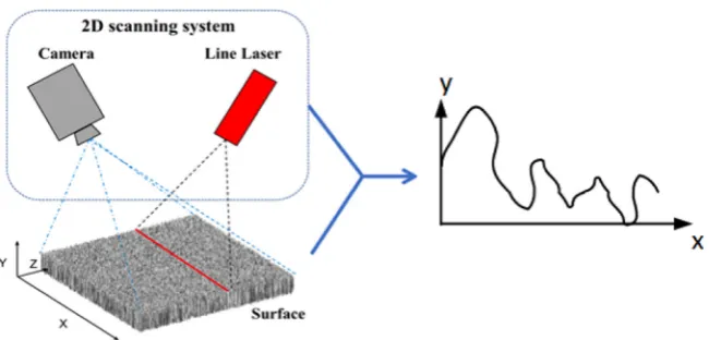
In our prototype, as illustrated in Figure 2, we employ out-of-the-shelf elements including a line laser source and a digital low-cost web camera to acquire images containing a laser projection. To extract the surface pro-file from a given object, we first capture a reference im-age with the laser line projection but without the object under test, as an image reference. Then, another image including the object is captured. Once data acquisition is complete, the corresponding 3D profile of surface levelness or depth can be extracted by processing and comparing the results derived from these two images, which is made within the MATLAB software. It is worth to clarify that this workflow only obtains the levelness for a given spatial line (x-axis) and, therefore, this working principle requires a linear actuator to measure a 2D sur-face, that is, both in x-axis and y-axis.
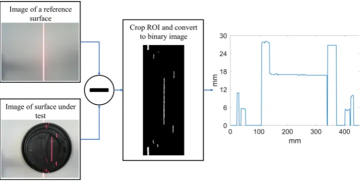
[image:3.595.134.465.65.221.2]apply a fixed (experimentally adjusted) threshold to bina-rize the resulting image. Given that the laser projects a given color (wavelength) line over the surface, this spec-tral information can be used for the binarization process. We can select any red, green, and blue (RGB) channel from the camera, in which the laser line can be domi-nant and easier to extract. As can be seen in Figure 3, the laser projection can be captured after subtraction and binarization. This laser projection appears mod-ulated according to the object to be measured, where the levelness or height H is proportional to the distance between the laser projected into the object and the la-ser in the reference image, following basic triangulation rules. Despite the simplicity of this approach, there are some intrinsic difficulties, as the reflection level varies depending on the different surface materials. Therefore, the projected laser line on the ground (reference image) is thicker than that on the object. To solve this, we de-fine the positions of lasers based on the central location from their width in both the reference and test image, namely, PR and PT , respectively. PR and PT are 1D vec-tors whose difference is proportional to the surface lev-elness along the x-axis, thus the levlev-elness or height H of the surface can be calculated by the following equation:
H x
( )
=σP xR( )
−P xT( )
,(1)
where σ is the depth parameter (constant for a given configuration), able to translate the horizontal distances between lasers (PR−PT) into the final height/levelness of
the object. The parameter σ is obtained from triangu-lation, where the relation between height H (levelness) and the laser distance (PR−PT ) is found thanks to the la-ser projection angle φ defined in the following equation:
tan 1
tan .
ϕ σ
ϕ = P −P =
H
R T
(
)
(2)
Experimental setup
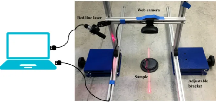
The experimental setup for surface levelness measure-ment is shown in Fig. The wavelength of the line laser is 650 nm (red color) with a length of 15 cm and a thick-ness of 3 mm at a distance of 20 cm. The resolution of the web camera, placed overhead and parallel to the ground, is of 640×480 pixels, and the incident angle between the laser and the ground is 45°. According to Equation (2), we thus have σ=1 for simplicity.
[image:4.595.121.484.68.250.2]These devices are mounted on a mechanical stage made by five beams and a laser bracket so that the camera elevation with relation to the reference ground is adjustable by two independent base brack-ets, where the working distance is normally around 15 to 30 cm. The orientation of the camera is adjusted to make the projected line laser completely vertical within the image. Both the camera and the laser are connected to and powered from a laptop (USB inter-face) and controlled by a software tool in MATLAB. In Fig, a coffee cap is used as a sample.
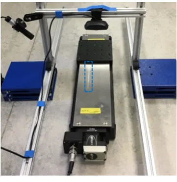
The working principle of our system aims to ob-tain the levelness profile along the x-axis, but for a fixed location in the y-axis. Therefore, this is provid-ing 1D measurements H(x). To obtain 2D levelness measurements H(x,y), a scanning process must be introduced in the system, where 1D profiles are ac-quired for several consecutive positions in y-axis. A mechanical linear actuator (ball screw) is used for this (Fig. 4). It is controlled by a high resolution (close to sub-millimeter) stepper motor in the scanning y-axis. Therefore, the sample to be measured moves along the y-axis, where in each step a 1D profile is obtained.
Results and discussion
To assess the performance of our proposed system, we develop experimental settings including three dif-ferent cases of study with increasing difficulty. In the first place, we test our system under a relatively easy task by measuring a simple surface (wooden wedge). In the second experiment, we try a much more com-plex measurement on a small toy with a challenging surface. These two cases are aimed to obtain a lev-elness profile along the x-axis from a given location, that is, the work is done in 1D, with fixed position in the y-axis (as illustrated in Fig. 2). For the third case of study, we introduce a linear actuator for acquiring a 2D levelness map. Results are provided in terms of subjective figures/plots and numeric results (mean square error, MSE). All real data in the experiment are measured manually by a digital calliper with a resolu-tion of 0.01 mm.
Simple surface 1D profile measurement
In this experiment, we test our system to check its performance in acquiring the levelness profile from a woody wedge (triangle shaped) sample as a simple case. The object to be measured has approximated a dimensions of 65 mm height, 165 mm length, and 40 mm width. It is placed in the system showed in Fig, where the laser line is projected onto it.
The figure (left) shows the acquired test image with the laser projected on the surface of the woody wedge, and the levelness measured by our approach (right). As can be seen, the extracted levelness (test data) closely matches the real 1D profile from the sample (real data). Only a small difference which is difficult to perceive is found, quantified in an MSE of 0.562 (Fig. 6).
Complex surface 1D profile measurement
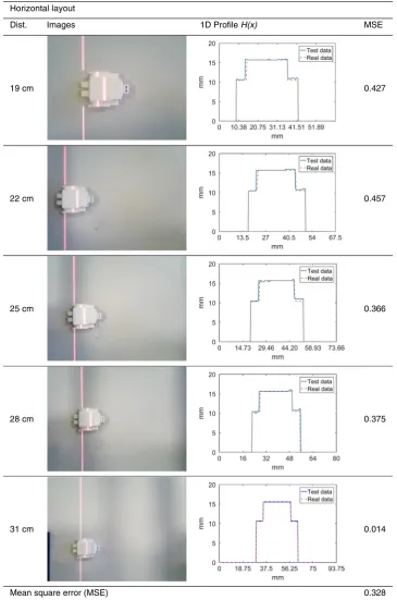
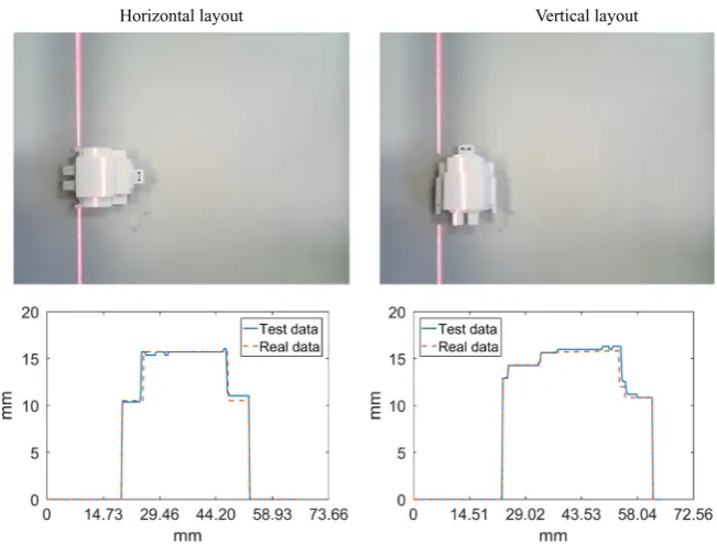
In the second case of study, a small toy is used as a sample with relatively complex surface. This toy is a small plastic robot with approximated dimensions of 50×40×15 mm. This sample was selected because the different surfaces available from the robot shape, including arms and legs, which makes it of a chal-lenging object. Additionally, for this experiment we place the camera at different distances from the sam-ple, ranging from 19 to 31 cm with a 3 cm step, to val-idate the performance of our system under different conditions. This is carried out twice, placing the robot both horizontally and vertically to acquire different lev-elness profiles (Fig. 7).
[image:5.595.116.473.68.237.2]Horizontal layout
1D Profile H(x) Images
Dist. MSE
19 cm 0.427
22 cm 0.457
25 cm 0.366
28 cm 0.375
31 cm 0.014
[image:6.595.101.467.103.655.2]0.328 Mean square error (MSE)
different levels are measured from the sample surface, where the acquired data matches highly consistent to the real profile. Small errors can be spotted in the top
[image:7.595.109.480.112.652.2]level at ~15 mm and one of the two 10-mm levels. How-ever, the overall performance seems satisfactory for our aims, quantified in an MSE of 0.366. In the second case,
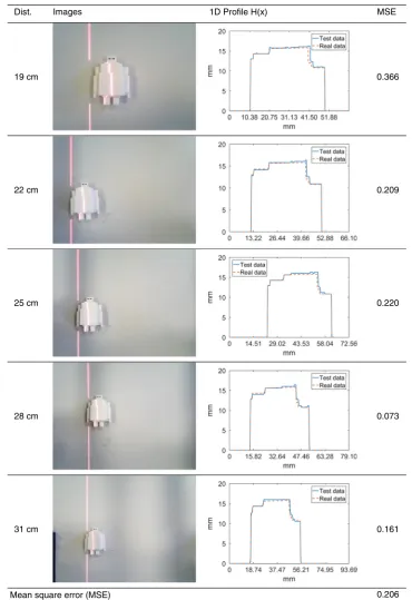
Table 3. Evaluated cases for complex surface measurement with vertical layout.
Images MSE
Mean square error (MSE) Vertical layout
1D Profile H(x) Dist.
19 cm 0.366
22 cm 0.209
25 cm 0.220
28 cm 0.073
31 cm 0.161
as the robot layout changes, the 1D profile presents different numbers of levels. Similar errors can be iden-tified through a close visual inspection, but it is worth to mention the excellent match in the left side of the profile (neck and chest of the robot toy). Actually, this measure-ment can be expressed in a reduced MSE of 0.220.
All evaluated cases are presented in Tables 2 and 3, which show the measurements from the sample with a horizontal layout and a vertical orientation, respectively. Every row provides the results for a different working distance between the camera and the object to meas-ure, adjusted by the base brackets in. For each combi-national case, the test image with projected laser line is presented, along with the 1D levelness profile H(x) and the related MSE obtained from test (measured) and real data. From these results, we see our system working
satisfactorily at different experimental conditions, prov-ing robustness and flexibility. In general terms, as we in-crease the working distance, results seem better. This is due to the image processing and segmentation of the laser, which is apparently more complex at closer dis-tances because of the reflections and higher width of the line laser. This means our prototype has still a big room for improvements by optimizing the experimental setup.
[image:8.595.112.293.67.253.2]Averaging all the cases shown, the global MSE obtained is of 0.267 mm, that is, our system is prov-en to easily achieve sub-millimeter accuracy at any of the working distances tested. This is a good trade-off between accuracy and cost, as our system can be achieved by roughly 100 USD, while other systems with a high accuracy (and probably less flexibility) can be around thousands of dollars, 10 times more than ours. For example, in Cai et al.’s (2016) study, authors use a plenoptic camera (Lytro 1.0) with 11 Megaray (107 rays) resolution and a DLP projector (Dell M110) with 800×1,280 resolution for experiments. The cost of the whole system is roughly 1,700 USD and its MSE is range from 0.0082 to 0.0125 mm as report-ed in their paper. In Cai et al.’s (2018) study, the au-thors use the same system reported in the study of Cai et al. (2016) for 3D reconstruction, the cost is still 1,700 USD and its MSE is about 0.0015 mm. In our daily life, sub-millimeter accuracy is enough to use. Although both methods have much higher accuracy, their practical applicability can be constrained due to the high cost. In the study of Huang et al. (2017), the 3D scanning system is composed by a Toshiba TLD-X2500A LCD projector with a resolution of 1,024×768 pixels and a 1/2 inch CMOS camera (Daheng Mer-cury-310-12uc) with a resolution of 2,048×1,536. The price of that system is around 300 USD and MSE is 3.5 to 5.5 mm reported in their paper. The price of this system is three times more than ours, yet their accu-racy (i.e. MSE) is much lower than ours.
Figure 5: 2D scanning system with a linear actuator; 2D map is obtained from attaching 1D profiles, where the laser line is highlighted in a dashed rectangle.
Figure 6: The experimental results for a simple surface (woody wedge), including (A) test image with projected laser line, and (B) obtained levelness H(x) from the wedge sample.
[image:8.595.137.465.552.687.2]2D levelness map measurement
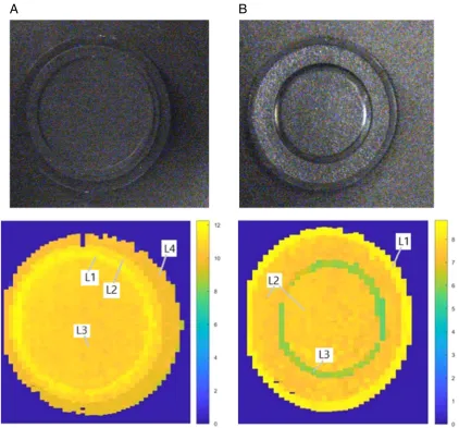
In the previous sections, our system was able to ac-quire 1D profile measurements, where levelness H(x) was obtained along the x-axis for a given position in the y-axis. This resulted in the plots shown in Fig and Fig. In this group of experiments, we aim to prove the effectiveness of our approach not only for 1D profile measurements but also for 2D levelness maps H(x,y) acquisition. The experimental settings adopted is the one introduced at the end of Section “Pro-posed structured light-based prototype” (in Fig. 5), where a linear actuator can move the sample to measure along the y-axis, allowing a 2D scanning. In other words, many different consecutive 1D profiles are acquired along the y-axis, resulting in a 2D map when attaching these 1D profiles together. For this experiment, two small caps are used as samples to measure. These are camera caps with a diameter of roughly 35 mm, having a surface with several levels which make them ideal for this purpose. The 2D level-ness maps obtained are shown in Figure 8 for cap (a) and cap (b). Real images of both caps are provided in the top row, while the levelness maps (in a MATLAB chart) are shown in the bottom row. In general terms, the levelness maps obtained are very close to the
[image:9.595.132.458.66.313.2]sur-face structure of the real samples, which proves that our system also has a good ability in 2D mapping. For cap (a), four main different levels are acquired; L1 and L2 (internal rings), L3 (central surface), and L4 (external surface), all of them with levelness H(x,y) re-ported in the lateral color bar, having as reference the ground surface (stated as 0 mm). In the same terms, three levels are obtained for cap (b); L1 (external ring), L2 (central surface), and L3 (internal ring). Looking at the real images of the caps in detail, it is easy to real-ize that there is small roughness texture within some of the levels. This is the reason why heterogeneity is found in some of the acquired levelness maps and indeed proves the capacity of the proposed system in detecting small sub-millimeter offsets. However, our system still exhibits some drawbacks; due to the low spatial resolution of the camera, the circular edges from the caps are not smooth but rough (pixelation effect). Furthermore, lighting conditions (basically re-flections) also affect the result. These can be poten-tially solved by introducing a slightly high quality web camera and put the system with covers to the side to reduce additional luminance. In summary, the ob-tained maps are satisfactory enough and again there is still a room for further improvements, including spe-cific light settings in the working environment.
Figure 7: The experimental results for a complex surface (robot toy), including test image with projected laser line (first row), and obtained levelness H(x) from the sample (second row). Working distance is 25 cm, and the sample is placed horizontally and vertically.
Conclusion
In this paper, a rapid surface levelness measurement system, with capabilities to provide 1D profile H(x) measurements with sub-millimeter accuracy, has been presented. The prototype approach is easy to op-erate and configure, simply consisting of a line laser (650 nm – red color), a low-cost camera (web camera), two adjustable brackets, and a mechanical stage/plat-form made of five beams. An optional linear actuator actioned by a stepper motor can also be employed to create 2D levelness maps H(x,y). With such elemental design, the proposed system is low-cost (around 100 USD) but able to provide sub-millimeter accuracy. This leads to a great trade-off between accuracy and cost,
[image:10.595.91.514.67.460.2]being much cheaper and competitive than other sys-tems for the similar purpose. According to the experi-mental tests and evaluations, our proposed system can work efficiently on different conditions including several materials (wood/plastics), shapes (basic/complex), and distances (19/31 cm), hence proving robust and with good potential in many application areas. Additionally, these results confirm that there is still a big room for improvements with no related cost, such as optimized experimental settings, and even real-time operation by automated algorithms. On a different note, there are other possibilities such as the use of higher resolution cameras, more controlled lighting/illumination, and the implementation of statistical/machine learning methods for improved image processing.
Figure 8: Real image (top) and obtained 2D levelness maps (bottom) from the surface of two samples (cap A and cap B). The levelness H(x,y) is measured by the color bar in mm.
Acknowledgments
This work is partially supported by the internal research Grant No. 2017-A-EN-05 obtained from Ajman Univer-sity, Guangdong Provincial Application-oriented Tech-nical Research and Development Special Fund Project (2016B010127006) and Guangdong Key Laboratory of Intellectual Property Big Data (No. 2018030322016).
Literature Cited
Brown, M. Z., Burschka, D. and Hager, G. D. 2003. Advances in computational stereo. IEEE Transactions on Pattern Analysis and Machine Intelligence 25(8):993– 1008, http://doi.ieeecomputersociety.org/10.1109/TPA-MI.2003.1217603.
Cai, Z., et al. 2016. Structured light field 3D im-aging. Optics Express 24(18):20324–34, https://doi. org/10.1364/OE.24.020324.
Cai, Z., et al. 2018. Ray calibration and phase map-ping for structured-light-field 3D reconstruction. Op-tics Express 26(6):7598–613, https://doi.org/10.1364/ OE.26.007598.
Chen, C. - Y., Yang, T.-T. and Sun, W.-S. 2008. Op-tics system design applying a micro-prism array of a sin-gle lens stereo image pair. Optics Express 16(20):15495– 505, https://doi.org/10.1364/OE.16.015495.
Eznaveh, Z. S., et al. 2017. All-fiber few-mode mul-ticore photonic lantern mode multiplexer. Optics Express
25(14):16701–7, https://doi.org/10.1364/OE.25.016701. Fang, Z., et al. 2017. 3D sensing techniques for mul-timodal data analysis and integration in smart and au-tonomous systems. International Conference in Com-munications, Signal Processing, and Systems, Springer, https://doi.org/10.1007/978-981-10-6571-2_71.
Hagebeuker, D.-I. B. and Marketing, P. 2007), A 3D time of flight camera for object detection, PMD Technologies GmbH, Siegen, available at: https://pdfs.semanticscholar. org/c5a6/366b80ba9507891ca048c3a85e6253fd2260. pdf.
Han, J., et al. 2013. Enhanced computer vision with Mi-crosoft Kinect sensor: a review. IEEE Transactions on Cyber-netics 43(5):1318–34, doi: 10.1109/TCYB.2013.2265378.
Huang, X., et al. 2017. Target enhanced 3D recon-struction based on polarization-coded structured light.
Optics Express 25(2):1173–84, https://doi.org/10.1364/ OE.25.001173.
Lussana, R., et al. 2015. Enhanced single-photon time-of-flight 3D ranging. Optics Express 23(19):24962– 73, https://doi.org/10.1364/OE.23.024962.
Mohanty, L. and Kuang, K. S. 2011. Surface structure
Engineering 49(7):984–7, https://doi.org/10.1016/j.opt-laseng.2011.01.028.
Nan-Nan, Z. and Jun, Z. 2016. Surface roughness measurement based on fiber optic sensor. Measure-ment 86:239–45, https://doi.org/10.1016/j.measure-ment.2016.02.051.
Sabri, N., et al. 2015. Fiber optic sensors: short re-view and applications”, Recent trends in physics of material science and technology, Springer: 299–311, https://doi.org/10.1007/978-981-287-128-2_19.
Salvi, J., et al. 2010. A state of the art in structured light patterns for surface profilometry. Pattern Recognition 43(8) 2666–80, https://doi.org/10.1016/j.patcog.2010.03.004.
Sandoz, P., et al. 2010. 3D localization of a labeled target by means of a stereo vision configuration with subvoxel resolution. Optics Express 18(23):24152–62, https://doi.org/10.1364/OE.18.024152.
Sarbolandi, H., Lefloch, D. and Kolb, A. 2015. Kinect range sensing: structured-light versus time-of-flight Ki-nect. Computer Vision and Image Understanding 139: 1–20, https://doi.org/10.1016/j.cviu.2015.05.006.
Van der Jeught, S. and Dirckx, J. J. 2016. Real-time structured light profilometry: a review. Optics and Lasers in Engineering 87:18–31, https://doi.org/10.1016/j.opt-laseng.2016.01.011.
Wang, Y., et al. 2018. 3D printed fiber optic face-plates by custom controlled fused deposition mod-eling. Optics Express 26(12):15362–76, https://doi. org/10.1364/OE.26.015362.
Wheaton, S., et al. 2017. Open architecture time of fight 3D SWIR camera operating at 150 MHz modulation frequency. Optics Express 25(16):19291–7, https://doi. org/10.1364/OE.25.019291.
Wu, T. T. and Qu, J. Y. 2007. Optical imaging for medical diagnosis based on active stereo vision and mo-tion tracking. Optics Express 15(16):10421–6, https:// doi.org/10.1364/OE.15.010421.
Xu, D., Zhou, W. and Peng, L. 2017. Three-dimen-sional live multi-label light-sheet imaging with synchro-nous excitation-multiplexed structured illumination. Op-tics Express 25(25):31159–73, https://doi.org/10.1364/ OE.25.031159.
Zanuttigh, P., et al. (Eds), (2016), Time-of-flight and structured light depth cameras, Springer, doi:10.1007/978-3-319-30973-6.
Zhang, S. 2018. High-speed 3D shape measure-ment with structured light methods: a review. Optics and Lasers in Engineering 106:119–31, https://doi. org/10.1016/j.optlaseng.2018.02.017.