Volume 2010, Article ID 474389,11pages doi:10.1155/2010/474389
Research Article
Efficient and Low-Cost 3D Structured Light System Based on
a Modified Number-Theoretic Approach
Tomislav Pribani´c,
1Hrvoje Dˇzapo,
1and Joaquim Salvi
21Faculty of Electrical Engineering and Computing, University of Zagreb, Unska 3, 10000 Zagreb, Croatia 2Institute of Informatics and Applications, University of Girona, Avenue Lluis Santalo s/n, 17071 Girona, Spain
Correspondence should be addressed to Tomislav Pribani´c,[email protected]
Received 8 May 2009; Revised 10 August 2009; Accepted 24 October 2009
Academic Editor: Jo˜ao Manuel R. S. Tavares
Copyright © 2010 Tomislav Pribani´c et al. This is an open access article distributed under the Creative Commons Attribution License, which permits unrestricted use, distribution, and reproduction in any medium, provided the original work is properly cited.
3D scanning based on structured light (SL) has been proven to be a powerful tool to measure the three-dimensional shape of surfaces, especially in biomechanics. We define a set of conditions that an optimal SL strategy should fulfill in the case of static scenes and then we present an efficient solution based on improving the number-theoretic approach (NTA). The proposal is compared to the well-known Gray code (GC) plus phase shift (PS) technique and the original NTA, all satisfying the same set of conditions but obtaining significant improvements with our implementation. The technique is validated in biomechanical applications such as the scanning of a footprint left on a “foam box” typically made for that purpose, where one of the ultimate goals could be the production of a shoe insole.
1. Introduction
Structured light (SL) upgrades a passive stereo camera system and becomes a powerful tool to achieve dense 3D acquisition [1]. In the simplest case, one of the cameras is typically replaced by a pattern projector such as a digital light projector (DLP) or a liquid crystal display (LCD). The task of the projector is to project patterns (images) with a given texture so that pattern pixels are coded in a certain way. Consequently, on the object’s surface the projector imposes a known code (texture) that is then acquired by a camera. The detection of correspondences between projected and imaged codes allows triangulation and hence the compu-tation of the 3D position of those codes on the measuring surface [2].
Considering the typical restrictions of the large number of SL methods, we define a set of conditions (SoCs) that optimal SL patterns should comply with the following.
(1) Every pixel of the projected pattern should contain the entire code and therefore potentially yield a cor-responding 3D point. This will create the conditions for high-resolution 3D reconstruction.
(2) There should be high distance between the code words of neighboring pixels. This will allow high sensitivity to spatial depth resolution.
(3) There should be robustness to object color/albedo reflectance properties. Any particular color calibra-tion adjustments or restriccalibra-tions to the ambient light should be avoided. This will assure almost immediate system use and applicability to various types of object surfaces and ambient light scenarios.
(4) There should be robustness to objects with sharp discontinuities and depth changes. This will guard against the problem of possible code perturbation and its misinterpretation during the decodification stage.
(5) The patterns should assure full 3D reconstruction where all three spatial coordinates of the object shape are attainable. In other words, ultimately computing only the depth coordinate with respect to one reference plane will not be satisfactory.
of addition, multiplication, comparison, and look-up table indexing. More complex image processing, such as finding edges, corners, detecting various shapes, centers of stripes, and color thresholding, should be avoided. Simple image processing will allow relatively easy implementation from a software point of view and fast processing, hopefully comparable with state-of-the-art commercial products.
(7) Only off-the-shelf components should be used. No special devices such as special lights sources or colorimeters should be part of the system. This will allow easy and affordable implementation from a hardware point of view.
One of the most powerful SL methods is phase shifting (PS), classified into time multiplexing strategies [3]. PS projects a sequence of periodic intensity patterns, so that every subsequent pattern is offset by a fraction of its period with respect to the previous pattern, covering the entire period. As a result, the so-called relative phase map (also periodic) is obtained, in which values readily available from the relative phase map are said to be wrapped in the range modulo 2π. Note that if there were not unwrapping problem, PS would perfectly fit SoC. A widely accepted solution to solve ambiguity of a single PS wrapped map is to combine it with Gray code (GC) [4]. The GC+PS technique is very effective and frequently regarded as the method of choice for the reconstruction of static objects [5]. In this case, the particular pattern period used to create the PS wrapped map is usually determined by the GC word length, since GC essentially codes the areas within every pattern period. However, there are research fields such as interferometry, where it is particularly convenient to work with patterns with variable periodicity. This type of research proposed a rather simple unwrapping solution called spatial unwrap-ping, which basically only works well on smooth surfaces since it assumes during the unwrapping procedure that the phase difference between neighboring pixels is less than π. An extension of this technique proposed an additional color-coded pattern, giving so a rough estimate to be used during the spatial unwrapping, at the expense that a colored pattern is basically restricted to color neutral objects [6]. Specially made hardware can be used to solve the problem of unwrapping [7]. Other proposed solutions concerned temporal phase unwrapping [8], which uses several wrapped PS maps and occasionally is referred to as multiple phase shifting (MPS). The simplest MPS unwrapping principle comes down to summing the wrapped phase differences between individual PS maps. Unfortunately, in order to achieve accurate 3D reconstruction, the amount of PS maps is typically fairly large in practice, for example, 20–30 maps as shown in [8]. Significant improvements appeared when the number of PS maps was reduced fromN to log2N [9], during which the periods of various PS maps follow a shorter exponential or other sequence [10, 11]. A very appealing approach was originally introduced by Gushov and Solodkin (referred to further as the G-S method) [12]. G-S is based on the number theoretic approach (NTA) where only two
patterns, with a larger number of periods, are considered, which is in theory sufficient to provide highly accurate 3D results (note that the number of periods has a direct effect on condition 2 in SoC). G-S is very fast since it comes down to the use of linear equations in which the inputs are simply the wrapped phases. Unfortunately, the straightforward implementation is very affected by unavoidable errors in wrapped phase computations. An interesting improvement is presented in [13] where the matrix of possible solutions is defined. Unfortunately, the computational time is related to the size of the search space, which dictates the probability that the right solution is contained within. Other usual improvements were offered in the form of more evolved 3D system design or the construction of look-up tables (LUTs), both of which might not be practical [14–16]. A typical problem with LUT is finite size, which limits the physical resolution. An alternative is to increase the size of LUT which leads to an increase in cost and computing time.
In this work we propose an MPS method based on significant improvements of a basic G-S. Our method checks and corrects, if necessary, the wrapped phase values obtained before the unwrapping computation is performed. In consequence, we do not need to use any LUT. We can readily use the wrapped values within the original G-S method to obtain a reliable unwrapped map. Consequently, our method is not influenced by wrapped phase computation inaccuracies as the original G-S method is and, besides, it is faster than common LUT-based (search) methods.
The remainder of this paper is structured as follows. In Section 2, we briefly explain the original G-S method and how it can be adapted to MPS pointing out the major problems. In Section 3, we present our proposal for overcoming such limitations and compare it to other SL techniques.Section 4 presents the setup of our system. Section 5includes an experimental evaluation of our method compared to the original G-S and GC+PS. Finally, we conclude by recalling the major points of the presented work.
2. Application of the Number-Theoretic
Approach in Multiphase Shifting
Two integer numbersΦABSandϕRare in congruence if they give the same remainder when they are divided by a given number λ. Hence, ΦABS and ϕR are said to be congruent moduloλ, as depicted in,
ΦABS≡ϕR(modλ). (1)
G-S takes advantage of a simultaneous solution to the following congruence equations:
ΦABS≡ϕR1(modλ1),
ΦABS≡ϕR2(modλ2),
.. .
ΦABS≡ϕRk(modλk),
1 2 3 4 5 6 7 8 9 10 11 12 13 14 15 Absolute phase
In
te
nsit
y
ΦABS
ϕR1
(a)
1 2 3 4 5 6 7 8 9 10 11 12 13 14 15 Absolute phase
In
te
nsit
y
ΦABS
ϕR2
(b)
Figure1: An example of two periodic intensity patterns and their relation to wrapped PS values.
whereΦABSandϕRiare integers andλiare positive integers but also relative primes. A solution to (2) is provided by the famous Chinese remainder theorem [17] depicted in,
ΦABS≡
k
i=1
ϕRi·eimod (λ1·λ2· · · ·λk), (3)
where the coefficientseican be computed as follows:
ei≡1 (modλi),
ei≡0
modλj
, i /=j .
(4)
Next consider, as shown in Figure 1, an ideal appear-ance of two sinusoidal periodic patterns (corresponding to wavelengths λ1 =5 and λ2 =3, resp.) which are meant to be projected and shifted. The abscissa axis corresponds to the unwrapped phase. Hence, every abscissa coordinate has a wrapped phase value, acquired throughout the pattern projection and shifting process, relative to the beginning of a period (e.g.,ϕR1=2 orϕR2=1 as shown inFigure 1). Evidently, the following conditions hold:
ΦABS=k1·λ1+ϕR1=k2·λ2+ϕR2, (5)
wherek1andk2are the number of periods typically unknown in practice, but necessary to reach some correspondingΦABS unwrapped value given some knownϕR1andϕR2. Note that bothΦABS andϕR1 divided byλ1 give the same remainder, ϕR1. Similarly ΦABS and ϕR2 divided by λ2 give the same remainder,ϕR2. Hence, we can set up a system of congruence equations (2) and find a solution forΦABS(3).
INTNUM INTNUM + 0.5 INTNUM + 1
ϕR Δ
Figure 2: Segment on the unwrapped phase axis between two integer numbers [INTNUM, INTNUM+1].
Until now and for simplicity we have assumed integer values for the wrapped phases ϕR1 and ϕR2. Of course, in practice, ϕR1 and ϕR2 are real numbers. Usually, the integer part is considered as an initial guess for computing ΦABS in (3). Then, ideally, the fractional partsϕR1FRAC and ϕR1FRACof both wrapped phases should be equal. However, in order to minimize noise influence, in practice, the mean values of both fractional parts are added to the initially computedΦABS in order to find the ultimate solution for the unwrapped phase. The well-known problem in the original G-S method was that ϕR1 andϕR2 were rounded and then used in (3). Consider that, due to noise, just one of the wrapped phases is slightly above an integer, when it should actually be just below that integer. Evidently, rounding (discarding a fractional part) gives a wrong input in (3), which is even magnified in the computation with the corresponding coefficientei. Consequently, the unwrapped phaseΦABSwill be quite apart from the correct one.
3. Proposition of a New Method
Our improvement is based on the fact that we actually have two major polices when computing an integer apart from the rational wrapped values: either rounding to the nearest integer or rounding to the nearest integer towards zero (alternatively infinity). In principle, all these types of rounding would work just fine. The only question is how to assure that all the wrapped phases are rounded towards the same corresponding value on the unwrapped phase axis and that, consequently, the rounding process provides the correct integer pair (ϕR1,ϕR2) to be used in (3). This is essentially the key issue, which is neglected in the original G-S method.
INTNUM+(0.5−Δ/2), rounding to the nearest integer will cause an erroneous integer pair (ϕR1, ϕR2). Besides, if Δ is too big, one of the wrapped phases might be within Δ, but the other could even be outside the interval [INTNUM, INTNUM+1]. In this case, rounding to the smaller integer will yield an erroneous integer pair (ϕR1,ϕR2).
Besides making an informal and rather intuitive argu-ment for the size of Δ, one should note the following. The rigorous mathematical formulation for the size of Δ effectively means a comprehensive analytical modeling of the noise sources, present during the computation of (un)wrapped phases. To name only a few factors, the noise sensitivity partly depends on the projector-camera physical setup and on the number of pattern periods, as explained in detail in [14]. Furthermore, the acquired image noise would have to be estimated, which depends on the quality of the camera and the projector, the lighting conditions and the object reflectance properties, among other aspects. On top of all that, the number of projected and shifted images also influences the computation of the wrapped phases. Evidently, the precise inclusion of all these factors in an a priori estimate of the size of delta is not an easy task and it is beyond the scope of this work. However, in practice, to acknowledge the influence of the above-mentioned factors we use a commercially available camera and projector, assuming it to be obvious that the results can only improve using better quality equipment. The chosen camera-projector physical setup is typical for a large number of 3D scanners. Next, we show a series of experiments with various commonly used pattern periods and in which we reach the point where the increase of pattern periods does not contribute to any gain in the reconstruction accuracy. We require no special ambient light conditions. In other words, we have extensively tested our chosen Δunder “common and widely acceptable” conditions. More specifically, the size Δ is determined for our setup partly intuitively and partly (confirmed) experimentally. We started computing the unwrapped phases withΔ=0.0 (which is equivalent to an original G-S method), gradually increasingΔby adding 0.01. Then we realized thatΔ=0.3 assures an excellent result for the computation of the correct wrapped values, as shown in this work. We emphasize that for a given camera/projector setup and choice of pattern period, the computation ofΔhas to be done only once.
For completeness, we briefly recall that PS wrapped phase valuesϕRfor every pixel are computed solely from the image intensitiesIiof theith shifted and projected image, as shown in:
Ii=I0+A·sin
ϕR−ϕi
, (6)
where I0 is the intensity when no source of projection is present (ambient light), A reflects the amplitude of the projected (detected in image) sine signal, and ϕi are the equally distributed shifts to cover the entire period. Note that the value ofA implicitly includes also the effect of the albedo/reflectance variation of a surface patch in the space which is projected into a particular pixel. Fortunately, an optimum result for the wrapped ϕR can be found through
a least square minimization of the difference between the left and the right sides of (6) [18]. Then for a number of imagesN ≥3 we obtain an expression for ϕR that ideally only depends onIi
ϕR=atan ⎛ ⎝−N−1
i=0 Ii·cos
ϕi
,
N−1
i=0 Ii·sin
ϕi
⎞⎠ , (7)
where atan is here the four quadrant inverse tangent function, yielding angleϕRin the interval [−π,π].
In the following paragraphs we summarize the key computational steps of our method.
Step 1. Given the periodic sine pattern, with the period lengthλ1, compute the wrapped phase valuesϕR1using the PS approach as explained through (6) and (7). Repeat this procedure for the other periodic sine pattern with the period lengthλ2in order to find out another set of wrapped phase valuesϕR2.
Step 2. Compute the coefficientseiin the equation using, for instance, the extended Euclidean algorithm [19].
Step 3. For any camera pixel and its corresponding wrapped phases pair (ϕR1,ϕR2), setΔ=0.3 and proceed as follows. Round the wrapped phase values to the closest smaller integer, if either of their fractional parts is within interval [0.5
−Δ/2, 0.5 +Δ/2]. Otherwise round it to the closest integer.
Step 4. Given the computed coefficients ei and rounded wrapped values, compute the initial unwrapped value using (3). Refine this initial solution by adding the mean value of the wrapped phases’ fractional parts, which were previously discarded during the rounding process.
Step 5. Verify by visual inspection that the unwrapped phase map image is correct. This is relatively easy since an inappro-priate value forΔwill give distinctly wrong unwrapped phase values (not just slightly wrong ones invisible to a human eye), for example,Figure 4(a)versus4(b). If necessary, repeat Step 3andStep 4using another value forΔ. Recall that the determination ofΔsize is normally executed only once after the spatial arrangement of the camera/projector setup and patterns periods are defined.
multiple shapes, for example, stripes or slits [20,21], lines [22, 23], circles [24, 25], squares [26], which are either colored or have gray level intensities. The main problem here is a high sensitivity to colorful surfaces and/or code misinterpretation due to sharp changes in the object’s depth (surface discontinuities). Up to a certain extent, both problems can be relaxed thanks to a color/reflectance calibration [27, 28] and dynamic programming [29, 30]. Another SL category is the so-called direct codification, where pattern points are encoded using a spectrum of gray level intensity [31] or colors [32], in which case the method is typically restricted for color neutral objects. Besides the problems of using color already mentioned, sometimes it is even necessary to use complicated hardware to project the color spectrum [33]. There have been some attempts to make improvements [34], but the biggest drawback in this category is the high sensitivity to noise, because the distance between adjacent codewords is nearly zero [35]. A somewhat special SL category is the Fourier transform profilometry (FTP), originally introduced in [36]. FTP is based ideally on imaging only a unique sinusoidal pattern while object depth is obtained from Fourier transformation computation, filtra-tion in spatial frequency domain, and inverse Fourier trans-formation calculation [37]. Unfortunately, the computed 3D depth is commonly restricted and highly dependent on the system parameters, which can be improved through the projection of an extra π-phase shifted pattern [38]. However, an extra pattern makes the method inapplicable for moving scenes, unless a prior knowledge about the object speed is known [39]. There are attempts to perform a π -phase shifted FTP constructing a single composite pattern either with or without a color codification [40,41]. Despite attempted improvements, the major drawback (motionless scenes) remains, as in any other (multi)frequency method: FTP faces the problem of blurred depth acquisition largely due to the nontrivial choice of the carrier frequencies related to the filtering step [42]. In conclusion, one of the very few known SL methods that do fulfill the SoC is the GC+PS approach which is extensively compared to our proposal. Other time-multiplexing methods aim to improve some shortcomings such as reducing the number of projection patterns at the expense of increasing the number of projected grey levels [43], or even trying to combine time-multiplexing with spatial neighborhood [44]. However, assuming that the number of patterns is not critical, all these methods are generally inferior to the classic GC+PS approach.
4. System Setup Description
Our 3D structured light system is composed of a calibrated pair of Point Grey Research (PGR) Dragonfly 2 FireWire camera and an Acer X1260 DLP video projector, which are rigidly attached on a bar. Camera images have a resolution of 1024×768 pixels. The distance of the camera and projector from the center of the calibration volume is about 900 mm and the baseline between the cameras and the projector is approximately 500 mm. The angle between the optical axes of the camera and the projector is of about 30◦.
Although a camera wand calibration is generally regarded as the most user friendly calibration approach, it normally assumes the use of infrared camera system [45,46]. Usually, a second best alternative is a plane calibration. Therefore, the camera was calibrated using a 2D calibration pattern with 11 ×8 white circles on a black background. The diameter of the circles was 15 mm and they were 10 mm apart. The camera calibration algorithm used closely resembles the one explained in [47]. We have acquired 18 images of the 2D calibration plate taken from different orientations and loca-tions throughout the calibration volume, which was of about 400 mm (width)×450 mm (height)×400 mm (depth). The centroids of the white calibration circles served not only to calibrate camera, but also to calibrate the projector. For every spatial position of the 2D calibration pattern (during camera calibration) we have projected the proposed pattern both in vertical and horizontal directions with respect to the projector image axis. We have searched for unique pattern codes (along both projector image axes) of centroids in the 2D pattern, and as we knew their 3D position (defined by the 2D calibration pattern), we were able to calibrate the projector using the same camera calibration algorithm [47]. For the camera the mean error and standard deviations between the detected calibration point’s positions on the images and the positions provided by the calibration model using computed calibration parameters were 0.090 pixels and 0.066 pixels, respectively. Similarly for the projector, the mean error and standard deviations were 0.149 pixels and 0.114 pixels, respectively.
5. Experimental Results
Table1: Mean error and standard deviations of distances for total ofNreconstructed points with respect to the fitted plane through those
Npoints.p1andp2show the chosen number of periods for periodic patterns used to construct wrapped PS maps.mis the Gray code word
length.
Proposed method
p1 p2 Pale plane Colorful plane
N Mean (mm) Std (mm) N Mean (mm) Std (mm)
3 5
121491
0.559 0.427
108846
0.675 0.610
5 7 0.269 0.251 0.443 0.422
7 11 0.241 0.183 0.341 0.329
13 17 0.177 0.143 0.253 0.227
19 25 0.152 0.122 0.232 0.215
25 29 0.149 0.119 0.224 0.239
G-S method
p1 p2 Pale plane Colorful plane
N Mean (mm) Std (mm) N Mean (mm) Std (mm)
3 5 112345 0.525 0.435 100567 0.667 0.593
5 7 93217 0.284 0.253 78456 0.468 0.489
7 11 67589 0.230 0.175 63976 0.337 0.318
13 17 63271 0.175 0.139 57349 0.244 0.220
19 25 54321 0.157 0.129 49345 0.228 0.217
25 29 52891 0.151 0.125 47975 0.209 0.226
GC+PS
m p1 Pale plane Colorful plane
N Mean (mm) Std (mm) N Mean (mm) Std (mm)
2 4
121491
0.934 1.061
108846
1.287 1.398
3 8 0.284 0.281 0.456 0.432
4 16 0.193 0.217 0.231 0.219
5 32 0.158 0.127 0.240 0.231
6 64 0.153 0.131 0.232 0.212
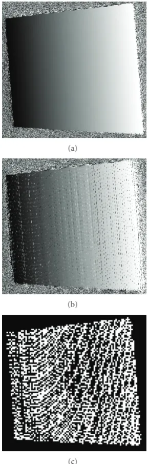
contribute to an increase in accuracy. In addition, eventually the three methods provide about the same level of accuracy. However, the original G-S method suffers from a serious decrease in attainable resolution. Due to the discussed noise intrinsic in G-S, for a large number of pixels it is not possible to unwrap the phase correctly. As expected, the problem becomes more serious when the periods are increased since the number of potentially noisy pixels then increases considerably. To visualize the effect of such invalid pixels, Figure 4 shows an unwrapped phase map of a flat surface using both our method and the G-S method (pattern periods used in both cases werep1=15,p2=19). However, it is important to note that although the reduced resolution might be acceptable, it needs costly image processing to automatically detect those invalid pixels. For all practical purposes, if the number of invalid pixels becomes excessive, it is very hard to detect them all and at the same time avoid discarding correct pixels, which leads to an additional decrease of resolution. Besides, it is possible that some of the invalid pixels remain undetected. To detect them, we have simply used a 3 ×3 pixel scanning mask, where we have computed for every pixel the abrupt changes of unwrapped values in a neighborhood of n pixels. Although it worked reasonably well, recall that according to our idea about
Figure3: Evaluation method for colorful surfaces. The figure shows a randomly generated colorful pattern which is printed and stuck on the measuring surface.
an optimal SL strategy (see SoC), such additional image processing should certainly be avoided and full projector resolution should be used.
(a)
(b)
(c)
Figure4: Appearance of the unwrapped phase map using the (a) proposed method and (b) the original G-S method; (c) shows (emphasized) in black all pixels with an incorrect unwrapped phase obtained by (b).
However, it is not straightforward to compare our method to GC+PS, since the patterns used are not exactly the same. The fact is that the length of the GC word of m bits typically determines the number of periods 2m to be used. The clear advantage of our method is when either GC images cannot be conveniently generated or some other arbitrary pattern periods are relatively easily available, such as in interferometry. In terms of color robustness we have appreciated a slight decrease in the accuracy for all the tested methods. That was surely expected to a certain extent, since the theoretical assumption of the full robustness to colorful surface is only a substantial idealization, which is particularly
hard to fulfill in the areas where abrupt changes of albedo take place.
As part of the qualitative evaluation of our method we have chosen to scan a foot impression from a “foam box” as shown in Figure 5 from three different viewing angles. We could acquire only the sole of the foot, without any lateral parts. In that case, a view similar to Figure 5(a) would be probably sufficient. Indeed that is how many commercial laser-based 3D systems dedicated particularly to the scanning of the foot (impressions) operate. However, in many applications (foot modeling), it may also be interesting to acquire parts of the lateral foot surface. Furthermore, to overcome the problem of occluded and/or shadow regions we have taken four scans. The problem of 3D surface registration from multiple views was solved using three white circular markers on our foam box [48]. In most cases our developed software automatically detects those markers on various images. If automatic detection fails, a user can manually add a rectangle around the white markers to roughly point out, for the underlying software, where the registration markers are.
Figure 6shows a 3D reconstruction result acquired from the single view corresponding toFigure 5(a). In more detail, Figure 6(a)is a mesh visualized from the top andFigure 6(b) is the same color mesh shown from the bottom. It is custom-ary to perform visualization with the help of colors where certain shades correspond to the depth of the impression in a foam box. Additionally, many professional software outputs 3D data in a variety of standard 3D file formats [49]. We have chosen to output our 3D scans in the STL format.Figure 7 shows the surface mesh visualization based on STL format of the registered model of the four scans. Very often the raw 3D data is smoothed prior to subsequent processing and modeling. The top row ofFigure 7shows the appearance of raw data, while the bottom row is a smoothed surface. The particular smoothing we have used is very basic: for every 3D raw data point we have defined a 1.5 mm cube in which that particular point was in the center. The new 3D position of a point was computed as the mean value of all its neighbors within a cube.
Although there are a number of systems available on the market to specifically scan the foot itself or impressions in a foam box [50–53], most of them are rather expensive and hardly applicable to a wide range of applications since they are aimed basically and exclusively at one particular application. In fact, many manufactures offer different type of scanners for different applications [54–57]. Additionally, they are frequently made from a custom-designed (often patented as well) system of laser scanning heads and/or image sensors [58,59]. However, our goal was to propose a widely applicable 3D structured light scanner that would also be cost effective, consisting of off-the-shelf components available to a large number of researchers.
(a) (b) (c)
Figure5: Images from three different views of the foot impression from our “foam box.”
200 150
100 50
0
0 20 40 60 80 100
30 20 10
(a)
0 50
100 150
200
100 80 60 40 20 0 10 20 30
(b)
Figure6: Impression from the foam box reconstructed from the single view: (a) the top perspective (b) the bottom perspective. Colors correspond to the different depth of the impression. The distribution of the colors is defined usingjetcolor map in Matlab.
(a) (b)
(a) (b)
Figure 8: An example of 3D human face reconstruction. (a) Image during pattern projection. (b) Acquired mesh surface: left, dense reconstruction obtained by our method; right, sparse reconstruction obtained by the G-S method.
method compared to the sparse 3D raw data originally obtained by G-S. Note that due to camera occlusion, mainly the left part of the human face was measured. This is of course an inherent drawback of basically all the optical 3D scanners. Alternatively, one could add an additional camera or try to perform a multiview surface registration, as mentioned above.
6. Conclusion
Our proposed 3D structured light scanner is based on, one of the most powerful structured light projection strategies, multiphase shifting. MPS is a representative of the so-called time multiplexing strategy. Following a coarse-to-fine paradigm, it can achieve high measurement accuracy, a feature certainly desired in biomechanics. To solve the main problem related to MPS, phase unwrapping, we have proposed a relatively simple method which involves a modifi-cation of the common G-S method. Comparing results to the original G-S method clearly demonstrated the superiority in terms of better 3D resolution and easier and faster image processing of our approach. Comparing our method to the well-known GC+PS reveals the same achieved accuracy, with the advantage that our method is easily applicable to a larger variety of chosen pattern periods. Besides, our method clearly fulfills several highly appreciated conditions (SoC) stated in the introduction concerning optimal SL strategy, which are not very common in SL methods. The acquired reconstruction accuracy is in line with most of the scanners available on the market. In addition, we have demonstrated how our approach performs for a biomechanics application: the scanning of a footprint in a given foam box. At the same time we have discussed the potential wider use in other applications involving living (moving) subjects, such as the scanning of the human face. Note that our scanner consists of a common (cheap) projector and a well-known yet affordable
camera. That fact warrants its implementation by a large number of researchers.
Acknowledgments
An important part of the shown work was steered through a visiting research enjoyed by the corresponding author at the Fraunhofer Institute for Computer Graphics Research (IGD) in Darmstadt, Germany. Special thanks go to Professor Dr.-Ing. Georgios Sakas and his Cognitive Com-puting & Medical Imaging Department for all the support provided at the time.
References
[1] J. F. Orr and J. C. Shelton,Optical Measurement Methods in Biomechanics, Chapman & Hall, Boca Raton, Fla, USA, 1997. [2] N. L. Chang, “Efficient dense correspondences using
tempo-rally encoded light patterns,” inProceedings of the IEEE Inter-national Workshop on Projector-Camera Systems in Conjunction with International Conference on Computer Vision (ICCV ’03), pp. 1–8, Nice, France, 2003.
[3] J. Salvi, J. Pag´es, and J. Batlle, “Pattern codification strategies in structured light systems,”Pattern Recognition, vol. 37, no. 4, pp. 827–849, 2004.
[4] G. Sansoni, A. Patrioli, and F. Docchio, “OPL-3D: a novel, portable optical digitizer for fast acquisition of free-form surfaces,”Review of Scientific Instruments, vol. 74, no. 4, pp. 2593–2603, 2003.
[5] G. Wiora, “High resolution measurement of phase-shift amplitude and numeric object phase calculation,” inVision Geometry IX, vol. 4117 ofProceedings of SPIE, pp. 289–299, San Diego, Calif, USA, 2000.
[7] N. Ono, T. Shimizu, T. Kurihara, and S. Ando, “Real-time 3-D imager based on spatio-temporal phase unwrapping,” in
Proceedings of the SICE Annual Conference, pp. 2544–2547, Sapporo, Japan, August 2004.
[8] H. O. Saldner and J. M. Huntley, “Temporal phase unwrap-ping: application to surface profiling of discontinuous objects,”Applied Optics, vol. 36, no. 13, pp. 2770–2775, 1997. [9] J. M. Huntley and H. O. Saldner, “Shape measurement
by temporal phase unwrapping: comparison of unwrapping algorithms,”Measurement Science and Technology, vol. 8, no. 9, pp. 986–992, 1997.
[10] W. Nadeborn, P. Andr¨a, and W. Osten, “A robust procedure for absolute phase measurement,”Optics and Lasers in Engi-neering, vol. 24, no. 2-3, pp. 245–260, 1996.
[11] J.-D. Tian, X. Peng, and X. Zhao, “A pitch-variation moir´e fringes method of temporal phase unwrapping profilometry,”
Optoelectronics Letters, vol. 3, no. 3, pp. 215–218, 2007. [12] V. I. Gushov and Y. N. Solodkin, “Automatic processing of
fringe patterns in integer interferometers,”Optics and Lasers in Engineering, vol. 14, no. 4-5, pp. 311–324, 1991.
[13] C. E. Towers, D. P. Towers, and J. D. C. Jones, “Time efficient Chinese remainder theorem algorithm for full-field fringe phase analysis in multi-wavelength interferometry,” Optics Express, vol. 12, no. 6, pp. 1136–1143, 2004.
[14] J. Burke, T. Bothe, W. Osten, and C. Hess, “Reverse engineer-ing by frengineer-inge projection,” inInterferometry XI: Applications, vol. 4778 ofProceedings of SPIE, pp. 312–324, Seattle, Wash, USA, July 2002.
[15] M. Takeda, Q. Gu, M. Kinoshita, H. Takai, and Y. Taka-hashi, “Frequency-multiplex Fourier-transform profilometry: a single-shot three-dimensional shape measurement of objects with large height discontinuities and/or surface isolations,”
Applied Optics, vol. 36, no. 22, pp. 5347–5354, 1997.
[16] J. Zhong and Y. Zhang, “Absolute phase-measurement tech-nique based on number theory in multifrequency grating projection profilometry,”Applied Optics, vol. 40, no. 4, pp. 492–500, 2001.
[17] P. Ribenboim,Algebraic Numbers, John Wiley & Sons, New York, NY, USA, 1972.
[18] C. J. Morgan, “Least-squares estimation in phase-measure-ment interferometry,”Optics Letters, vol. 7, no. 8, pp. 368–370, 1982.
[19] K. H. Rosen,Elementary Number Theory and Its Applications, Addison-Wesley, Reading, Mass, USA, 1988.
[20] M. Tehrani, A. Saghaeian, and O. Mohajerani, “A new approach to 3D modeling using structured light pattern,” in
Proceedings of the 3rd International Conference on Information and Communication Technologies (ICTTA ’08), pp. 1–5, Dam-ascus, Syria, 2008.
[21] J. Pag´es, J. Salvi, and J. Forest, “Optimised de Bruijn patterns for one-shot shape acquisition,”Image and Vision Computing, vol. 23, no. 8, pp. 707–720, 2005.
[22] H. Kawasaki, R. Furukawa, R. Sagawa, and Y. Yagi, “Dynamic scene shape reconstruction using a single structured light pattern,” in Proceedings of the 26th IEEE Conference on Computer Vision and Pattern Recognition (CVPR ’08), pp. 1– 8, Anchorage, Alaska, USA, June 2008.
[23] T. P. Koninckx and L. Van Gool, “Real-time range acquisition by adaptive structured light,” IEEE Transactions on Pattern Analysis and Machine Intelligence, vol. 28, no. 3, pp. 432–445, 2006.
[24] P. M. Griffin, L. S. Narasimhan, and S. R. Yee, “Generation of uniquely encoded light patterns for range data acquisition,”
Pattern Recognition, vol. 25, no. 6, pp. 609–616, 1992.
[25] C. Albitar, P. Graebling, and C. Doignon, “Design of a monochromatic pattern for a robust structured light coding,” inProceedings of the IEEE International Conference on Image Processing (ICIP ’07), pp. 529–532, San Antonio, Tex, USA, October 2007.
[26] M. Ito and A. Ishii, “A three-level checkerboard pattern (TCP) projection method for curved surface measurement,”Pattern Recognition, vol. 28, no. 1, pp. 27–40, 1995.
[27] D. Caspi, N. Kiryati, and J. Shamir, “Range imaging with adaptive color structured light,”IEEE Transactions on Pattern Analysis and Machine Intelligence, vol. 20, no. 5, pp. 470–480, 1998.
[28] F. Forster, “A high-resolution and high accuracy real-time 3D sensor based on structured light,” inProceedings of the 3rd International Symposium on 3D Data Processing, Visualization, and Transmission (3DPVT ’06), pp. 208–215, Chapel Hill, NC, USA, 2006.
[29] P. Fechteler and P. Eisert, “Adaptive colour classification for structured light systems,”IET Computer Vision, vol. 3, no. 2, pp. 49–59, 2009.
[30] L. Zhang, B. Curless, and S. Seitz, “Rapid shape acquisition using color structured light and multi-pass dynamic program-ming,” inProceedings of the 1st International Symposium on 3D Data Processing, Visualization, and Transmission (3DPVT ’02), pp. 24–36, Padova, Italy, June 2002.
[31] B. Carrihill and R. Hummel, “Experiments with the intensity ratio depth sensor,” Computer Vision, Graphics, & Image Processing, vol. 32, no. 3, pp. 337–358, 1985.
[32] C. Wust and D. W. Capson, “Surface profile measurement using color fringe projection,”Machine Vision and Applica-tions, vol. 4, no. 3, pp. 193–203, 1991.
[33] J. Tajima and M. Iwakawa, “3-D data acquisition by rainbow range finder,” inProceedings of the 10th International Confer-ence on Pattern Recognition (ICPR ’90), vol. 1, pp. 309–313, Atlantic City, NJ, USA, June 1990.
[34] T. Sato, “Multispectral pattern projection range finder,” in
Three-Dimensional Image Capture and Applications II, vol. 3640 ofProceedings of SPIE, pp. 28–37, San Jose, Calif, USA, 1999.
[35] G. Chazan and N. Kiryati, “Pyramidal intensity-ratio depth sensor,” Tech. Rep. 121, Department of Electrical Engineering, Center for Communication and Information Technologies, Technion, Haifa, Israel, 1995.
[36] M. Takeda and K. Mutoh, “Fourier transform profilometry for the automatic measurement of 3-D object shapes,”Applied Optics, vol. 22, no. 24, pp. 3977–3982, 1983.
[37] X. Su and W. Chen, “Fourier transform profilometry: a review,”Optics and Lasers in Engineering, vol. 35, no. 5, pp. 263–284, 2001.
[38] J. Li, X. Su, and L. Gou, “An improved Fourier transform pro-filometry for automatic measurement of 3-D object shapes,”
Optical Engineering, vol. 29, no. 12, pp. 1439–1444, 1990. [39] E. Hu and Y. He, “Surface profile measurement of moving
objects by using an improvedπphase-shifting Fourier trans-form profilometry,”Optics and Lasers in Engineering, vol. 47, no. 1, pp. 57–61, 2009.
[40] W. Chen, P. Bu, S. Zheng, and X. Su, “Study on Fourier transforms profilometry based on bi-color projecting,”Optics and Laser Technology, vol. 39, no. 4, pp. 821–827, 2007. [41] H.-M. Yue, X.-Y. Su, and Y.-Z. Liu, “Fourier transform
profilometry based on composite structured light pattern,”
[42] C. Guan, L. G. Hassebrook, and D. L. Lau, “Composite structured light pattern for three-dimensional video,”Optics Express, vol. 11, no. 5, pp. 406–417, 2003.
[43] E. Horn and N. Kiryati, “Toward optimal structured light patterns,”Image and Vision Computing, vol. 17, no. 2, pp. 87– 97, 1999.
[44] I. Ishii, K. Yamamoto, K. Doi, and T. Tsuji, “High-speed 3D image acquisition using coded structured light projection,” in Proceedings of the IEEE/RSJ International Conference on Intelligent Robots and Systems (IROS ’07), pp. 925–930, San Diego, Calif, USA, October 2007.
[45] T. Pribani´c, P. Sturm, and M. Cifrek, “Calibration of 3D kinematic systems using orthogonality constraints,”Machine Vision and Applications, vol. 18, no. 6, pp. 367–381, 2007. [46] T. Pribani´c, P. Sturm, and S. Peharec, “Wand-based calibration
of 3D kinematic system,”IET Computer Vision, vol. 3, no. 3, pp. 124–129, 2009.
[47] Z. Zhang, “A flexible new technique for camera calibration,”
IEEE Transactions on Pattern Analysis and Machine Intelligence, vol. 22, no. 11, pp. 1330–1334, 2000.
[48] J. Salvi, C. Matabosch, D. Fofi, and J. Forest, “A review of recent range image registration methods with accuracy evaluation,”
Image and Vision Computing, vol. 25, no. 5, pp. 578–596, 2007. [49] Paracontour modelling software, September 2009,http://www
.londonorthotics.co.uk/loc-technology/foot-scanner.html. [50] “FotoScan 3D,” September 2009,http://www.precision3d.co
.uk.
[51] InFoot, September 2009, http://www.iwl.jp/main/products .html.
[52] “EcoPlan,” September 2009, http://www.shoemaster.co.uk/ products/eco plan.html.
[53] “CanFit-Plus,” September 2009,http://www.vorum.com. [54] Breuckman, September 2009,http://www.creativecadcam.net/
3d-white-light-scanner.html.
[55] Inspeck, September 2009,http://www.inspeck.com. [56] Cyberware, September 2009,http://www.cyberware.com. [57] “DigiScan dental scanner,” September 2009,
http://www.rsi-gmbh.de/public/en/rsi/news.htm.
[58] Scanny3D, September 2009,http://www.scanny3d.com. [59] Steinbichler, September 2009, http://www.central-scanning