Abstract: This paper describes a tree structure antenna with defected ground structure & CPW feeding. In this proposed antenna, Swasthik layer defected ground structure has been considered to achieve wide-band & ultra-wideband (UWB) characteristics for impedance matching. The simulation bandwidth matching from S11<-10dB and frequency from 5GHz-20GHz. The Swasthik shape antenna is designed for the enhancement of multiband frequency applicable for L-band, D-band & SHF-band. The antenna performance evaluating the dense antenna that is applicable for portable communication devices.
Index terms- defected ground structure, CPW feeding, microstrip antenna, FR4 epoxy
I. INTRODUCTION
Nowadays, the trend is developing devices for wireless communication system which have inherent high bandwidth, gain & multi-resonance. The electromagnetic waves are received and transmitted by the antenna. So, it is very challenging for the speed of receiver and transmits when there is the fast development in the communication technology.(1)
The 2D, 3D, and planar antennas are used for the communication applications. As per the antenna requirement, instance or stabile devices like wire material are used. For other applications wireless sensors or devices, mobile devices are used for the personal body network; the receiver-transmitter should be low profile: so it can take less area in the PCB. For personal body network or wireless network, the flexibility of the antenna must be high: so that it can easily bend even if it is close to 90 degree.(2)
In recent years, the micro-strip antenna has made progress in wireless communication. Micro-strip antennas are more popular these days because of; it has better results and more advantages over conventional antenna. These antennas are low weighted; cost is low, low profile, easy to design, low volume, and congruity. Dual circular polarization, dual frequency operations are provided by the micro-strip patch antenna. To improve the bandwidth of the proposed antenna, DGS & CPW feed techniques are used in this paper.(1,3) The aim of this paper is to present the advantages of DGS & CPW in dense size of the antenna as well as to obtain the wide frequency band and impedance matching. Different
Revised Manuscript Received on June 15, 2019.
Rakhi Sharma,Department of Electronics & Communication, Chandigarh Group of Colleges Landran, Mohali, India.
Dr. Sukhdeep Kaur, Department of Electronics & Communication, Chandigarh Group of Colleges Landran, Mohali, India.
Dr. P N Hrisheekesha, Professor & Campus director of Chandigarh Group of Colleges, Mohali, India.
Dr. Pooja Sahni, Department of Electronics & Communication, Chandigarh Group of Colleges Landran, Mohali, India.
feeding effects and ground plane effects can be measured at different frequencies by taking DGS & CPW structure.
II. ANTENNA DESIGN
As above mentioned, a novel tree shape ultra-wideband design with Swasthik Defected Ground structure & CPW has been proposed. In this design, Figure.1 shows that the proposed antenna looks like as to have tree like patch and DGS,CPW shows the antenna geometry 60mm×60mm×1.6mm. The antenna is designed on FR4 epoxy substrate of 1.6mm thickness with the relative constant €r=4.3. In this design, one side of the antenna contains tree shape path and on another side is ground. The electromagnetic software Ansoft HFSS R19 is used to numerically investigate & optimized the proposed antenna. The design concept and measurements results of the UWB antenna are discussed in the subsequent sections. The antenna impedance bandwidth with S11<-10dB is more than 10GHz, in both simulation and measurement.(7,10)
Fig.1: Geometry of the proposed antenna
TREE Shape Micro-Strip Antenna using Stack
Layer DGS
Table I: Parameters for the proposed antenna
Parameters Size (mm)
Length of the substrate 60mm
Width of the substrate 60mm
Length of the ground 60mm
Width of the ground 60mm
Length of the feed line 26mm
Width of the feed line 5.25mm
III. RESULTS & DISCUSSIONS A. Return loss
Return losses will be infinite if all the power is transferred to the load. A good antenna gives the low return losses as possible, the return losses should be less than -10dB. If the return losses are more than -10dB the antenna is not properly designed. In Figure.2, the simulated result shows that the proposed antenna exhibits the ultra wide band characteristics having resonant frequency from 5GHz to 20GHz. The return losses of this proposed antenna lies as -21dB and -26dB respectively.(3,4)
Fig.2: Simulation results of the proposed antenna
B. Current distribution
[image:2.595.88.248.369.544.2]In this proposed antenna, Figure.3 & Figure.4 shows the current distribution for electric field and for the magnetic field at the resonant frequency at 1GHz is stable. For higher radiation pattern, the E-field and H-field is in the same phase: causes the current distribution more balanced.(5)
Fig.3: Electric field & Magnetic field distribution
Fig.4: Radiation pattern of the proposed antenna
By using different feeding techniques, it can enhance the bandwidth of the proposed antenna. These feeding techniques help to enhance the input impedance of the antenna.
IV. DEFECTED GROUND STRUCTURE- TREE
ANTENNA
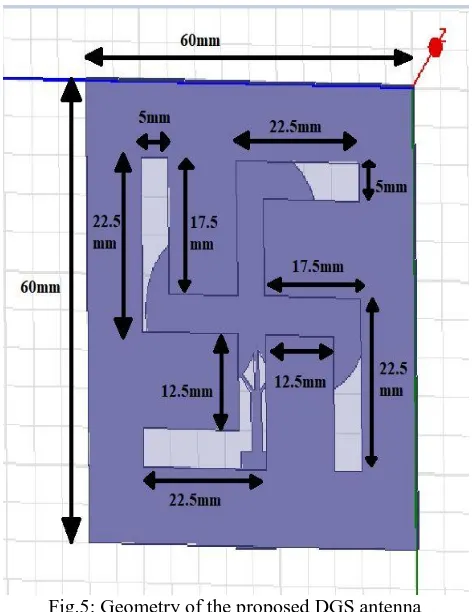
In this design, the Swasthik shape slot cut on the ground plane to enhance the radiation pattern & input impedance of the proposed antenna as shown in the Figure.5. The locations and dimensions of the defect are orthogonal: so they do not affect the dominant mode
Swasthik shape geometry 40mm×40mm×1.6mm, it is designed on FR4 epoxy substrate with relative constant €r=4.3.(4,6)
[image:3.595.51.287.94.400.2]Fig.5: Geometry of the proposed DGS antenna
Table II: Parameters of the proposed DGS antenna Parameters Size (mm)
Length of the substrate 60mm
Width of the substrate 60mm
Length of the ground 60mm
width of the ground 60mm
Length of the DGS cut 40mm
Width of the DGS cut 40mm
V. RESULTS & DISCUSSIONS A. Return loss
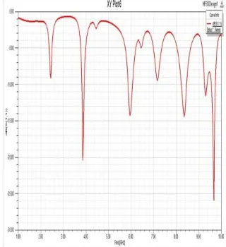
[image:3.595.337.518.373.608.2]In Figure.6, the simulated result shows that the proposed DGS antenna exhibits ultra wide band characteristics with the resonate frequencies of 5 GHz to 20 GHz: the return losses are -14dB and -26dB respectively. The simulation result of this proposed antenna is higher & also it increases the radiation pattern and bandwidth.(8)
Fig.6: Simulation result of the proposed DGS antenna
B. Current distribution
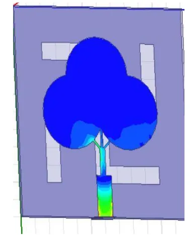
[image:3.595.42.281.424.624.2]Fig. 7: Electric field & Magnetic field distribution
Fig. 8: Radiation pattern of the proposed DGS antenna
VI. CPW FEED-TREE ANTENNA
[image:4.595.305.525.49.212.2]As already mentioned, the proposed antenna is further designed to enhance the bandwidth & radiation pattern. In this design, the two grounds are etched on the same plane of the antenna: one on the top of the substrate and another one in the bottom as shown in the Figure.9. This design is introduced to obtain ultra-wideband accompanied with good impedance matching over the entire operating band. It is designed on the FR4 epoxy substrate with the relative constant €r=4.3, the geometry of this proposed DGS antenna is given below.(7,9)
Fig.9: Geometry of the proposed CPW feed antenna
VII. RESULTS & DISCUSSIONS A. Return loss
The simulation result of this antenna having the resonant frequency 5GHz TO 20GHz, the return losses occurred -24dB and -28dB respectively. In this design the simulation results are very high than other feeding techniques as shown in the Figure.10: which describes the maximum power transferred to the patch through feed line.(9)
Fig. 10: Simulation result of the proposed CPW-feed antenna
B. Current distribution
[image:4.595.310.539.337.549.2]Fig. 11: Electric field & Magnetic field distribution
Fig. 12: Radiation pattern of the proposed CPW-feed antenna
VIII. COMPARISON
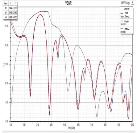
By using different feeding techniques, the simulation result also changes. As the Figure.13 shown below, the result of the DGS & CPW feed are much better than the proposed antenna. The DGS and CPW miniaturize the size of antennas as well as to widen the bandwidth.
Fig. 13: Comparison graph for various feeding techniques
[image:5.595.316.538.312.528.2]As shown in Figure.14, by using the CPW feed, we are capable of lower-loss performance at much higher frequencies, & also capable to moderate radiation loss at millimeter wave frequencies.(10)
Fig. 14: Effect of the different feed gaps
IX. CONCLUSION
This paper presents a novel TREE shape antenna with Defected Ground structure & CPW feeding. The designed antenna is also suitable for UWB operations in the 3GHz to 11GHz; also the antenna performance of the operating frequencies across the wider frequency band is very good. It simulates the impedance bandwidth of this antenna for S11<-10dB is from 5GHz to more than 20GHz. The total antenna size is (60*60*1.6) sq.mm. By comparing the various feeding techniques: DGS & CPW, it is observed that the CPW feeding technique proves better than all other results because it is giving good result.(10)
REFERENCES
1. ParulDawar, N. S. Raghava, Asok De. “UWB Metamaterial-Loaded Antenna for C-Band Applications”, International Journal of Antennas and Propagation, 2019
2. Tale Saeidi, Idris Ismail, Wong Peng Wen, Adam R. H. Alhawari,
Ahmad Mohammadi.
“Ultra-Wideband Antennas for
Applications”, International Journals of Antennas and Propagation, 2019 3. A. Nouri, G. R. Dadashzadeh. “A Compact UWB Band-Notched Printed Monopole Antenna With Defected Ground Structure”, IEEE Antennas and Wireless Propagation Letters, 2011
4. D. Guha, M. Biswas, Y.M.M Antar. “Microstrip Patch Antenna With Defected Ground Structure for Cross Polarization Supression”, IEEE Antennas and Wireless Propagation Letters, 2005
5. Pei, Jing, An Guo Wang, and Wen Leng. “A Novel Arc-Shaped Printed Antenna for WLAN Applications”, Applied Mechanics and Materials, 2011 6. Geetanjali Singla, Rajesh Khana. “Modified CPW-fed rotated E-slot antenna for LTE/WiMAX applications”, International Journal of Microwave and Wireless Technologies, 2014
7. SonaliKatoch, Harshita Jotwani, ShuchismitaPani, AsmitaRajawat. “A Compact dual band antenna for IOT applications”, 2015 International Conference on Green Computing and Internet of Things (ICGCIoT),2015 8. AshnaKakkar, Nirdosh, Shalini Sah. “A tri-band circular patch microstrip antenna with different shapes in DGS for Ku and K applications”, 2017 2nd International Conference on
9. Anil Kr Gautam, SwatiYadav, Binod Kr Kanaujia. “A CPW-Fed Compact UWB Microstrip Antenna”, IEEE Antennas and Wireless Propagation letters, 2013
10. “Table of contents”, IEEE Transactions on Antenna and Propagation, 2018
AUTHORSPROFILE
Rakhi Sharma received B.Tech (Engg.) Degree in ECE in 2017 from, Himachal Pradesh Technical University. Presently she is pursuing her M.Tech from CGC Landran, Mohali. Her main research interest is in antenna and wireless communication.
Sukhdeepkaur received B.Tech (Engg.) Degree in ECE in 2001 from, Amravati University and M.Tech from GNE Ludhiana in 2008. And done Ph.d from Thapar University, Patiala in 2016. Presently, she is working as Professor in ECE Deptt. at CGC, Landran. She has more than 50 publications to her credit in referred international journals and has presented more than 25 papers in international and national conferences. Her main research interest includes antennas and wireless communication.
P. N. Hrishikesh born in 1967 in India. He received B.E. degree from National Institute of Engineering, University of Mysore, Mysore, India in 1988 and M.Tech degree from National Institute of Engineering, Mysore, Visweswaraiah Technological University, India in the year 2000. He received Ph.D degree from Indian Institute of Technology Roorkee, India in 2010. Currently he is working as Campus Director of CGC, Landran. He has published over 20 papers in international and national conferences /journal. His research interest includes AI application to power system operation and control, distributed generation, embedded generation and distribution system automation.