EFFECTONVIBRATIONAMPLITUDEINALUMINIUMRECTANGULAR
PLATEUSINGSIMULATIONAPPROACH
NURNAJAAMASTURABINTIMOHAMADJAMIL
EFFECTONVIBRATIONAMPLITUDEINALUMINIUMRECTANGULAR
PLATEUSINGSIMULATIONAPPROACH
NURNAJAAMASTURABINTIMOHAMADJAMIL
Thisreportissubmitted
infulfillmentoftherequirementforthedegreeof BachelorofMechanicalEngineering(DesignandInnovation)
FacultyofMechanicalEngineering
UNIVERSITITEKNIKALMALAYSIAMELAKA
ii
DECLARATION
I declare that this project report entitled “Effect On Vibration Amplitude In Aluminium Rectangular Plate Using Simulation Approach” is the result of my own work except as cited in the references.
Signature : ...
iii APPROVAL
I hereby declare that I have read this project report and in my opinion this report is sufficient in terms of scope and quality for the award of the degree of Bachelor of Mechanical Engineering (Design & Innovation).
iv DEDICATION
v ABSTRACT
vi ABSTRAK
vii
ACKNOWLEDGEMENTS
It is such a great pleasure and gratitude to acknowledge people whose guidance and encouragement contribute tremendously towards the completion of my final year project.
First and foremost, a huge thank you to my supervisor Dr. Mohd Azli Bin Salim for giving me this opportunity to do final year project with him, being supportive in coaching and sharing knowledge with me and guiding me throughout the entire period of this final year project.
viii
TABLE OF CONTENT
CHAPTER CONTENT PAGE
DECLARATION ii
APPROVAL iii
DEDICATION iv
ABSTRACT v
ABSTRAK vi
ACKNOWLEDGEMENT vii
TABLE OF CONTENT viii
LIST OF FIGURES xi
LIST OF TABLES xiv
LIST OF SYMBOL xv
CHAPTER 1 INTRODUCTION 1
1.1 Introduction of Study 1
1.2 Problem Statement 3
1.3 Objectives 3
1.4 Scope of Project 3
CHAPTER 2 LITERATURE REVIEW 4
2.1 Introduction 4
2.2 Theory of Plate 4
2.3 Free Vibration of Plate 5
2.4 Flexural Wave 6
ix
CHAPTER CONTENT PAGE
CHAPTER 3 METHODOLOGY 10
3.1 Introduction 11
3.2 Mathematical Modelling 12
3.2.1 Wave Equation 12
3.3 CATIA Software Analysis 17 3.3.1 Step before conduct the modal analysis by 17
using CATIA.
3.3.2 The component of the body. 21 3.3.3 Condition used for CATIA analysis. 23 3.3.3.1 First Condition 23 3.3.3.2 Second Condition 24 3.3.3.3 Third Condition 24 3.3.4 Step for the modal analysis of frequency case 25
CHAPTER 4 RESULTS AND DISCUSSION 28
4.1 Introduction 28
4.2 CATIA Software Analysis 29
4.2.1 First Condition 30
4.2.2 Second Condition 33
4.2.3 Third Condition 36
4.2.4 Discussion 39
4.3 Data and Result 40
4.3.1 First Condition 41
4.3.2 Second Condition 42
4.3.3 Third Condition 43
x
CHAPTER CONTENT PAGE
CHAPTER 5 CONCLUSION AND RECOMMENDATION 45
5.1 Conclusion 45
5.2 Recommendation 46
REFERENCES 47
xi
LIST OF FIGURES
FIGURE TITLE PAGE
1.1 The schematic diagram of rectangular plate. 2
2.1 Natural frequencies of rectangular plate with various thickness 5
2.2 The frequency of different mode number. 6
2.3 Normal-mode amplitudes for flexural waves of the rectangular 6 plate.
2.4 LR-MS Model 8
2.5 Penang Second Bridge 9
2.6 Rubber bearing under Penang Second Bridge 9
3.1 Schematic diagram of beam. 12
3.2 The change of length of element. 12
3.3 Part design option. 17
3.4 Plane selection. 18
xii
FIGURE TITLE PAGE
3.6 Pad definition. 19
3.7 Material selection. 19
3.8 Insert body. 20
3.9 The labeled holes. 23
3.10 Single plate. 23
3.11 Plates with spring holders. 24
3.12 Plates with springs, rubber and base. 24
3.13 Springs with spring holders. 24
3.14 Analysis & Simulation option. 25
3.15 Frequency case option. 25
3.16 Clamp option. 26
3.17 Applying the load. 26
3.18 Compute the simulation. 27
4.1 Result of simulation. 29
4.2 The vibration amplitude occurred on the plate. 40
xiii
FIGURE TITLE PAGE
4.4 Graph of percentage error for analysis of first condition. 41
4.5 The plat with spring holders. 42
4.6 Graph of percentage error for analysis of second condition. 42
4.7(a) The plates with springs, rubber between the second condition’s 43 plates.
4.7(b) Springs on spring holders. 43
4.8 Graph of percentage error for third condition. 43
xiv
LIST OF TABLES
TABLE TITLE PAGE
3.1 Component of the body 21
4.1 Result of frequency analysis for first condition. 30
4.2 Result of frequency analysis for second condition. 33
4.3 Result of frequency analysis for third condition. 36
4.4 Result of analysis for first condition. 41
4.5 Result of analysis for second condition. 42
xv
LIST OF SYMBOL
f = Frequency A = Area
CL = Velocity of propogation D = Longitudinal stiffness dx = Displacement
E = Modulus of elasticity K = Wave number
P = Pressure = Strain = Wave length
= Density = Stress
1 CHAPTER 1
INTRODUCTION
1.1 INTRODUCTION OF STUDY
The application of plate plays a big role which is the most commonly used structures in the industrial world. In the structured design, plate is stated only to withstand applied static loads which are inadequate for the application. Possibility of large cyclic displacement and stresses should be considered due to periodic or random time changing the forces acting on the plate’s lateral surface.
Some examples for the issue are the aircraft components or stationary structures exposed to high wind velocities which random forces are expected on the plate surface, tangential fluid force on plate surface used in ship hulls, submarines or offshore structures and regular or periodic excitation forces on plates used as structural housing on rotating or reciprocating machinery like compressors and reciprocating engines.
2
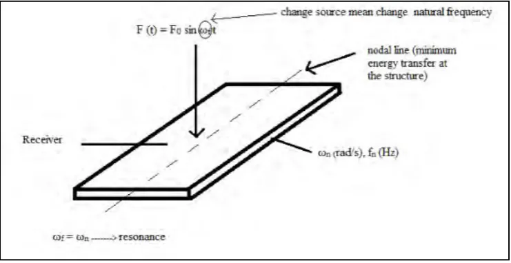
Figure 1.1: The schematic diagram of rectangular plate.
There are several steps to analyze the forced vibration. Before solving the problem, the value of natural frequency and mode shape need to be determined. Then, it can assist to analyze free vibration or forced vibration where the focus are known as amplitude of vibration.
3
1.2 PROBLEM STATEMENT
The vibration analysis is a significant step for obtaining the result of frequency on the aluminium rectangular plate. The problem of the structured design is when there is matching between driving forces and the plate’s natural frequencies which is known as resonance. The analysis is needed to avoid the possible resonance from occur in the application.
1.3 OBJECTIVE
The objective of this study is to study the vibration effect of aluminium plate using simulation technique.
1.4 SCOPE OF PROJECT
The scopes of this study are:
4 CHAPTER 2
LITERATURE REVIEW
2.1 INTRODUCTION
Literature review is the information gathering which already exists in the previous research or project. The purpose of literature review is to define the research topic and it consists of several information of the previous research. The information can be obtained from referring to journal, article or information from website. Relevant sources from online articles and websites are compiled and cited to complete this literature review. Hence, by review the related information, it will help to understand the objective of the research.
2.2 THEORY OF PLATE
5 2.3 FREE VIBRATION OF PLATE
Basically there are three boundary conditions of plate that will affect the amplitude vibration occur on it which are simply supported, clamped and free. The boundary condition can be mixed with each other or just the same condition. It is important to prevent from the resonance which will happen when there is matching between driving forces and the plate natural frequencies. Free vibration analysis is significant to avoid resonance between the plate and driving force system.
From the previous research, the study is about free vibration analysis with three different boundary conditions by using Bessel functions. The conditions chosen are fully simply supported, fully clamped and the last one is the mixed condition which is two opposite boundaries with simply supported and another two boundary with clamped. The result of the analysis is appeared to be the natural frequency obtained is different for each boundary condition (Wu et al., 2007).
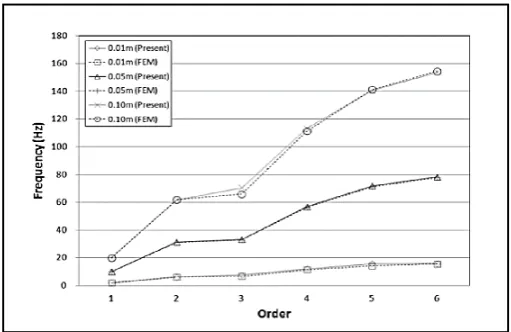
[image:21.595.194.450.525.691.2]Another research had been made about the analysis of free vibration by using characteristic orthogonal polynomials in assumed mode method. The analysis is done by comparing the different thickness of the plate. As a result, higher thickness increased the natural frequency of the plate as shown in the graph analysis in Figure 2.1 below (Kim et al., 2012).
6
2.4 FLEXURAL WAVE
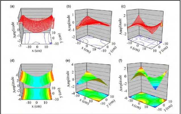
[image:22.595.116.537.186.350.2]The previous research had done the flexural vibration analysis of a rectangular plate for the lower normal modes. The results show that different mode number produce different frequency. The frequency increased as the mode number is bigger as shown in Figure 2.2.
[image:22.595.163.482.419.619.2]Figure 2.2: The frequency of different mode number. (Manzanares-Martnez et al., 2010)
Figure 2.3: Normal-mode amplitudes for flexural waves of the rectangular plate. (Manzanares-Martnez et al., 2010)
7
2.5 SEISMIC ISOLATION SYSTEM
Currently, the further research from Korea Atomic Energy Research Institute found that the response of seismic isolation system is affected on the variability of the mechanical properties of lead rubber bearings, the response depends on the movement for different ground motions. The researcher states that the variation in the mechanical properties of base isolator will result significant influence on the shear resistance and the acceleration response of the structure.
It was discovered that the response of the isolation system is increased by the lower limit in variations, while the response of the superstructure is increased by the upper limit in variations. The upper limit in the stiffness variation of the isolators can reduce the decoupling performance of the isolation system (Choun, Park, & Choi, 2014). In the application of seismic isolation system, the building structures need to be related with safety, the different type in the materials and mechanical properties of the isolation system must be carefully controlled, furthermore to minimize the accidental torsion caused by the different similarity stiffness of variation isolators.
8
2.6 LAMINATED RUBBER-METAL SPRING (LR-MS) MODEL
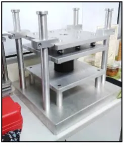
[image:24.595.261.384.256.405.2]Laminated rubber-metal spring is the multiple layer of rubber layer and metal plates were arranged alternating. The number of layer is determine based on the frequency vibration condition. A research had been done by the Centre for advanced Research on Energy, Universiti Teknikal Malaysia Melaka. By using dynamic analysis of finite element method, the performance of vibration transmissibility of LRMS can be determined. The laminated rubber-metal spring model is shown in Figure 2.4 below.
Figure 2.4: LR-MS Model