Interfaces and Space Charge in Polymeric Insulating Materials
G. Chen
School of Electronics and Computer Science University of Southampton, UK
ABSTRACT
In this paper, the influence of interface between electrode and polymer or polymer and polymer on space charge dynamics has been studied. Planar samples of low density polyethylene (LDPE) were subjected to high dc electric stresses for extended periods of time and space charge measurements were taken using the pulsed electroacoustic (PEA) technique. Common electrode materials used in either laboratory or power cable industry were selected (i.e. aluminium (Al), gold (Au) and carbon loaded XLPE (Sc)).
Experimental results demonstrated that charge injection processes take place in all cases once the applied electric stress has exceeded a threshold value. However, the amount of charge and polarity of the dominant injected charges showed a significant dependence on the electrode materials (under the same applied electric stress). Having establishing the influence of electrode materials on charge accumulation, our attention was then focused on the effect of polymer/polymer interface on charge dynamics. Unlike our previous approach where two different polymeric materials were used, this time the
polymer/polymer interface was formed by using two layer of LDPE films cut from the same sheet. Sc and Al were used as electrodes to form different combinations. The results clearly indicated that the interface between two layers of LDPE acts as traps for electrons but not for positive charge carriers. The charge distribution in the bulk of the sample strongly depends on the electrode materials.
INTRODUCTION
Interfaces are often encountered in practical insulation systems and have become a growing area of interest due to their influence on the electrical performance of whole system. Unlike the case of semiconductors where transistors and diodes utilize
characteristics of interfaces (p-n junctions), the interfaces in high electrically stressed materials, whether polymer/metal or polymer/polymer, can cause accumulation of space charge which can lead to unwanted electric field modification. For example, the interfaces in cable joints and terminations of extruded high voltage cables have been identified as crucial parts as their failure probability is much higher than cable itself. It has been proposed [1] that the accumulated space charge at the interface is a more significant factor with regard to electric field enhancement than in the bulk. Despite of increasing interests in the interfaces, the underlying mechanisms related to charge formation and electrical ageing are not well understood and research into the best interfacial materials and its binding structure is
becoming increasingly important. Initially, thermally stimulated discharge current (TSDC) technique has been used to study polymer/polymer, polymer/mica and polymer/oil
(LDPE)/ethylene vinyl-acetate (EVA) laminates, have proposed that positive charges injected from the EVA side accumulate near the interface. Recently, Hozumi et al [6] have studied the charge behavior in a similar system using the pulsed electroacoustic (PEA) technique. They have found that the heterocharge is dominant at the interface. It has been established that PE-based materials may have considerable concerns when used for dc power cable, particularly in the presence of voltage polarity inversions [7]. These concerns were related to the presence of space charge in the insulation which can increase the risk of degradation due to local stress enhancement, ionisation and energy storage [8-9].
The present paper describes the charge formation and distribution in a system containing both electrode/polymer and polymer/polymer interfaces. Electrode materials considered are Al, Au and semiconducting polymer (Sc). Al and Au have been widely used as electrodes in laboratory while Sc is employed in polymeric power cables. For polymer/polymer interface, we have adopted a different approach from the previous research [10] where the interface is formed from different polymers, the interface in the present study is formed by laminating similar LDPE films.
EXPERIMENTAL DETAILS AND TEST PROTOCOL
LDPE was chosen because of its relatively simple chemical structure and its wide applications in cable insulation. Space charge formation in a material is greatly affected by the presence of impurities and additives as they can act either as ionisable centers under a high electric stress or as trapping sites. In order to reduce the influence of impurities, additive-free low-density polyethylene (LDPE) was selected for the present study. The thickness of the sample was typically ~200 µm thick for a single layer, consisting of two layers of ~100 µm thick films for two layer arrangement. Al electrodes with a diameter of 8 mm was evaporated on the sample under vacuum less than 2x10⁻⁵ torr. Au electrode with a similar size to Al electrode was sputter coated on to the sample. For a semicon electrode material, a thin tape was removed from the outer screen (made of Borealis Semiconducting Compound LE 0592) of a commercial power cable and a
The electrical behaviour of the interfaces is affected by several factors such as contact pressure, temperature and smoothness of the surfaces. Interfaces without microscopic cavity do not exist and some surface scratches in micron order are inevitable. In order to avoid partial discharges arising from the scratches the size of the cavities should be kept as small as possible. Care has been taken during sample preparation. The observation using the scanning probe microscopy (in the Atomic Force Mode) reveals the scratches on the surface of the LDPE films are less than 1µm.
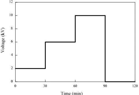
The sample was stressed at different voltage levels up to 10kV for a period of time at room temperature. The voltage profile in the present study is shown in Figure 2.
The space charge measurements were taken at various times during the periods of both ‘volts on’ and ‘volts off’ (short-circuit condition) using the pulsed electroacoustic (PEA) technique. In the PEA technique, acoustic pressure waves are generated due to the
[image:3.612.111.351.231.395.2]interaction of pulsed electric field and charge layer. Detection of acoustic pressure waves allows one to determine charge distribution across the sample.The principle of the PEA is shown in Figure 3. The pulse generator was able to produce a pulse width of 5ns with various amplitudes. The sensor used was a 9 µm thick LiNbO3 material that enables the
Figure 3 Schematic diagram of PEA system
Vs(t)
transducer Vdc
Vp(t)
Sam ple
Vs(t)
d p(t)
electrode electrode
Detecting
ρ(x)
system to be heated up to 90oC although this was not utilized in the present study. A constant pressure was maintained during the measurements.The spatial resolution of a PEA system is determined by the pulse width, acoustic speed in the material and sensor thickness. It was estimated that the spatial resolution of the present PEA system is less than 10 µm which is considered adequate in the present study. The calibration of space charge was performed at the beginning of 2 kV voltage application.
RESULTS
Samples with the Same Electrode Materials
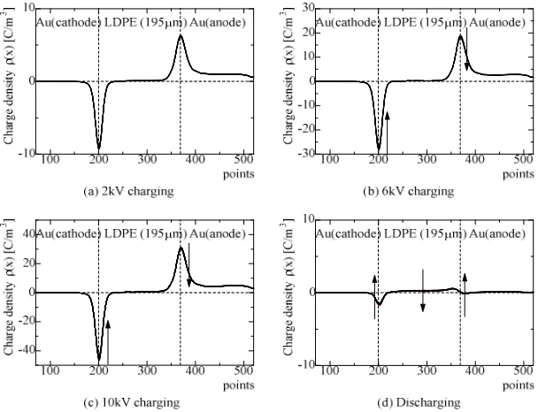
Figures 4 to 6 show the space charge build up in a single layer of LDPE with 2 kV, 6 kV and 10 kV applied to the sample with the same electrode materials.
Figure 4 Space charge formations in Al-LDPE-Al with different voltages.
in the samples with Sc and Al electrodes suggests that the injection occurs at both electrodes.
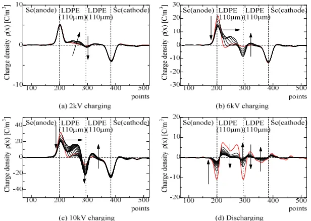
[image:5.612.101.405.174.395.2]From the above it is clear that Au injects little charge compared to the other two electrode materials. Therefore, in the following sections we only show the results from Al and Sc electrode materials. Figures 7 and 8 illustrate the space charge build up in two layer of LDPE for various voltages applied to the sample with the same electrode materials.
Figure 5 Space charge formations in Sc-LDPE-Sc with different voltages.
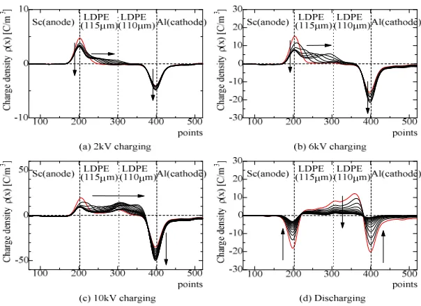
[image:5.612.101.405.437.670.2]Figure 7 Space charge formations in Al-LDPE/LDPE-Al with different voltages.
It can be seen from Figure 7 that even at 2 kV a small amount of negative charge can clearly be seen at the LDPE/LDPE interface. As expected, the amount of the injected charge increases with the applied voltage. At 6 kV one starts to see the positive charge on the both sides of the interface. This becomes even clear at 10 kV. The negative charge accumulation at the interface is a key feature. The amount of charge is generally smaller compared with that in Figure 8. Charge decay rate seems to be slower.
Figure 8 Space charge formations in Sc-LDPE/LDPE-Sc with different voltages.
[image:6.612.99.407.435.654.2]is formed when increasing the applied voltage. At the end of the voltage application of 6 kV, there is a significant amount of positive charge accumulated in the layer next to the anode with its maximum close to the polymer interface. In the layer next to the cathode, charge distribution is more complicated. There is a large amount of negative charge accumulated adjacent to the polymer interface followed by a small amount of positive charge in the middle of the layer. The broad peak due to the charge on the cathode indicates the presence of negative charge adjacent to the cathode. The above charge distribution becomes much clear when 10 kV was applied to the sample. The charge distribution measured immediately after the removal of 10 kV is in agreement with the ‘volts on’ observation. The charge decreases with time and the rate at which the charge decays is very fast.
Samples with Different Electrode Materials
Figures 9 and 10 show the results obtained from single layer samples with different electrode materials. Figure 9 shows the space charge profiles from the sample with Sc as the anode and Al as the cathode. A large amount of positive charge is found in the sample with its maximum in the middle of the sample at the end of 10 kV applied voltage.
Figure 9 Space charge formations in Sc(+)-LDPE-Al(-) with different voltages.
If Sc and Al electrodes are swapped the charge distribution in the sample is quite different as shown in Figure 10. Here negative charge is developed close to the cathode (Sc) and positive charge close to the anode. The amount of charge is smaller comparing with that observed when Sc as the anode.
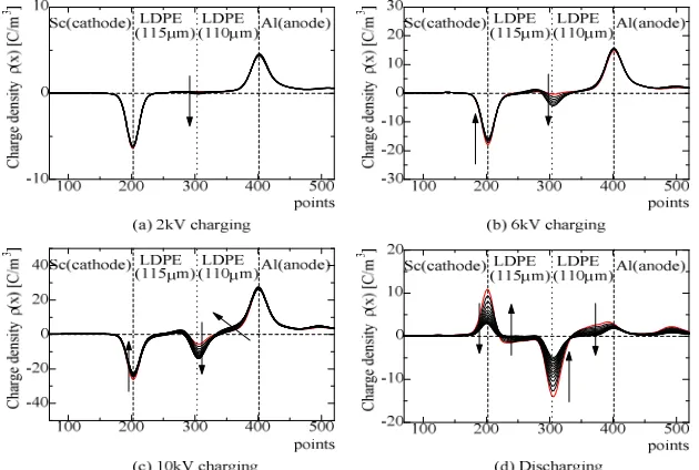
Figures 11 and 12 illustrate the space charge formation for the two layer structure. It can be seen from figure 11 that at 2 kV there is a small amount of negative charge
cathode with its maximum close to the polymer interface. Further increase in the applied voltage leads to more charge being injected into the bulk. Generally the measurement at different times shows that the amount of charge in the bulk also increases with the duration of the voltage application. The remaining charge measured is shown in Figure 11 (d) after the applied voltage is removed. The distribution differs slightly from that when the applied voltage is applied. It can be seen that negative charge appears in the layer next to the Sc electrode and positive charge in the layer next to the Al electrode. Again at the interface there is a large amount of negative charge. Compared with the sample that has the same electrodes the amount of negative charge at the interface is lower than for Sc electrodes but higher than for Al electrodes.
Figure 10 Space charge formations in Sc(-)-LDPE-Al(+) with different voltages.
[image:8.612.92.407.486.698.2]When the polarity of the electrodes is reversed, i.e. Sc as the anode and Al as the cathode, charge dynamics are different as shown in Figure 12. At 2 kV there is a small amount of positive charge in the bulk with its maximum adjacent to the anode. The amount of positive charge increases with the applied voltage and the maximum moves from the interface at 6 kV to the region adjacent to the cathode at 10 kV. Compared the results with those obtained previously, there are two features: only positive charge is observed across the bulk and there is no subtle change in charge distribution at the polymer interface. Charge decay in this case is fairly fast.
Figure 12 Space charge formations in Sc(-)-LDPE/LDPE-Al(+) with different voltages.
DISCUSSION
Same Electrode Materials
The results presented above clearly demonstrate that the electrode materials have a significant effect on charge injection. This will subsequently affect charge trapping and transportation in the material. As mentioned earlier, the material used in this investigation is additive-free LDPE therefore the impurity effect should not be a major player in the charge generation. Bear this fact in mind; the charge formed in the sample can be attributed to charge injection from the electrodes. It is generally considered that at the electrodes, electron injection or extraction (hole injection) occurs by either thermionic emission over a stress-lowered potential barrier (so called Schottky emission) or
well. Once injected the positive charge can travel through the bulk under the influence of the effective electric stress and distribute across the sample. It is also possible that
negative charge is injected into the sample from the cathode, however, the amount of negative charge is so small and is negligible compared with the amount of positive charge. Based on the amount of charge accumulated in the sample it indicates Al electrode can inject slightly higher amount of holes than Au electrode. In the case of Sc electrodes, two features are obvious from the charge distribution; (i) the amount of negative charge in the bulk is larger than positive charge, this indicates that electrons inject easier than holes from Sc. (ii) electrons distribute broadly toward the anode while the holes are close to the anode, this indicates the apparent mobility of electron is higher than hole. It is believed that the injected electrons move quickly through the bulk and meet the injected holes near the anode where they are recombined with holes.
From the above results it clearly illustrates that in the case of metallic electrodes hole injection from the anode is easier than electron injection from the cathode. It is also clear that hole injection from Al anode is easier than that from Au anode as the amount of charge in the bulk is higher when the anode is Al. One may also say that the electron injection from Au cathode is extremely difficulty. This may be explained based on the work function of the materials. In the case of Al and Au as electrode, it is known [11] that the work function of Au (4.70±0.02eV) is higher than Al (4.08±0.05eV) therefore the potential barrier of Al/LDPE interface is lower than that of Au/LDPE interface. As a result, there should be more injection from Al than Au, leading to a higher conduction current. Based on this argument the Sc used in the present study is carbon loaded XLPE and should have a very similar structure to the LDPE from the energy-band point of view. Consequently, the potential barrier between them is negligible, so the injection should be much easier than the metal electrode. The amount of charge trapped within the bulk of the sample validates the argument.
As for samples consisted of two layer LDPE films, the polymer interface seems to dominate charge dynamics in the sample. According to the electromagnetic theory [12], charge density, σ, at an interface between two dielectrics is determined by the following equation
)
1
(
)
(
)
(
1 12 1 2 2 1 2 1
2
E
ε
E
γ
γ
ε
γ
γ
ε
ε
σ
=
−
=
−
where
γ
1and
γ
2represent the conductivities of material 1 and material 2,
ε
1and
ε
2the
dielectric constants of material 1 and material 2 respectively. This theory has been
employed to describe charge formation and decay at the interfaces between different
polymeric materials [13], however, it experienced a difficulty in explaining quantitatively
the amount of charge present at the interfaces. An attempt has been made to explain the
charge formation at the interface formed between different materials such as EVA and
LDPE in our earlier research [10] using the theory. It only agreed in terms of charge
polarity. In the present study, as the same material is involved, therefore we have
) 2 ( 1 2 1 2
γ
γ
ε
ε
=system. It is well known that the conductivity of insulating materials is dependent on the
electrical stress [14], while the permittivity of the materials is less influenced by the
electric stress. Secondly, charge transportation in the material is influenced by the
presence of traps and trapping characteristics. In particular, due to broken bonds and
chain folds at the surfaces of the materials the traps originated from the surface states
play an important role in forming charges. The charge polarity is determined by the
nature of surface states. In my opinion, the surface states dominate the nature of charge
trapped.
Different Electrode Materials
Charge distributions in the samples with different electrode materials are interesting. The
amount of charge and polarity in single layer LDPE samples are mainly determined by
the Sc electrode. In the case of Sc and Al electrode combination the charge distributions
are quite different from the pure metallic electrodes. In Figure 9 where the Sc is the
anode and Al the cathode, the maximum positive charge occurs at the centre of the
sample. It is believed that positive charge is injected from the anode. As mentioned
earlier that Al cathode can actually inject electrons, the injected electrons tend to move
towards the anode and neutralise with the coming holes. However, the amount of
electrons is significantly lower than holes. As a consequence, the front of positive charge
approaches the cathode slowly. The process can be accelerated by electric field as shown
in Figure 9 (c) where 10 kV was applied. As more positive charge is injected into the
bulk the interfacial stress at the anode is reduced, therefore, the amount of injected charge
becomes less.
When Sc acts as the cathode and Al as the anode, electrons dominate with the maximum
at the polymer interface. The electric field in the layer next to the Al electrode is
enhanced, resulting in an increase in positive charge carrier injection. The positive charge
carriers may be able to cross the interface but will be recombined with the large amount
of electrons from the Sc electrode, hence the charge distribution as shown in Figure 10.
In the case of two layer samples the charge distribution is determined by Sc as well as
polymer interface. When Sc is served as the anode as shown in Figure 11, no negative
charge is observed. Considering possible electron injection from Al electrode and
trapping characteristic of the polymer interface, it may be possible that a small amount of
negative charge presents at the polymer interface. The PEA measurement can not
distinguish positive and negative charge and only give a net charge. When Sc is served as
the cathode, charge distribution is dominated by negative charge and concentrated at the
polymer interface.
The accumulation of space charge in polymeric materials has serious effect on electric
field distribution. Although not presented in this paper, the electric field enhancement
caused by the presence of bulk charge can be comparable with the applied electric field.
This is indeed a factor that needs to be taken into consideration in practice. Growing
evidence shows that space charge plays an important role in electrical aging and
CONCLUSIONS
The effects of interfaces of electrode material/polymer and polymer/polymer on the
charge trapping characteristics in low-density polyethylene have been investigated, the
following conclusions may be drawn:
The electrode material has a significant effect on the charge injection therefore on the
trapping characteristics of LDPE. From carrier injection point of view the results indicate
that for electron the order is as follows: Sc > Al while Au injects very little; for hole the
order is Sc > Al > Au. The injection rate in the case of Al electrodes is hole > electron
while with Sc electrodes the injection rate is electron > hole.
The interface between two layers of LDPE acts as traps for electrons but not for positive
charge carriers. The charge distribution in the bulk of the sample strongly depends on the
electrode materials.
REFERENCES