Theses
Thesis/Dissertation Collections
5-1-1998
A Study of aircraft lateral dynamics & ground
stability
Howard Brott
Follow this and additional works at:
http://scholarworks.rit.edu/theses
This Thesis is brought to you for free and open access by the Thesis/Dissertation Collections at RIT Scholar Works. It has been accepted for inclusion
Recommended Citation
&
Ground Stability
by
Howard W. Brott Ir
A Thesis Submitted
In
Partial Fulfillment
of the
Requirements for the
MASTER OF SCIENCE
In
Mechanical Engineering
Approved by:
Professor
-Dr. Kevin Kochersberger
Thesis Advisor
Professor
_
Dr. Alan Nye
Professor
_
Dr. Michael Hennessey
Professor
_
Dr. Charles Haines
Department Head
DEPARTMENT OF MECHANICAL ENGINEERING
COLLEGE OF ENGINEERING
ROCHESTER INSTITUTE OF TECHNOLOGY
Permission
Granted
I, Howard W. Brott Jr., hereby grant permission to the Wallace Memorial Library of
Rochester Institute of Technology to reproduce my thesis entitled: A Study of Aircraft
Ground Stability and Lateral Dynamics, in whole or in part. Any reproduction will not be
for commercial use or profit.
May21,1998
Thestability of anaircraft ontherunway is dependentonmany factors. In this
thesis, amathematical modelisdevelopedthatallowsthegroundstability and lateral
dynamics of an aircraft tobe analyzedwhileit is intheprocess of
taking
off orlanding.Only
two degrees-of-freedomwillbeconsidered: lateral displacementand angularrotation. Equationsof motion forthemodel are developed using Newtonianmechanics.
Themajor components oftheaircraftthatare included inthemodel are the main
landing
gear, thevertical tail,andthe tailwheel. Themodelis developedinto both linearand
non-linearforms.
Comparisons are madebetween atricycle gearaircraft and ataildragger.
Simulations for boththelinearand non-linear model are performed tobetterunderstand
stability. The results ofthesesimulations are usedtocomment onthe applicabilityofthe
Abstract iii
TableofContents iv
ListofTables vi
ListofFigures vii
ListofSymbols xi
Chapter 1 Introduction 1
Chapter 2 Literature Review 7
Chapter 3 Tire Model 1 1
3.1 Introduction 1 1
3.2 Lateral Force 12
3.3 Linear Tire Model for Main
Landing
Gear 163.4 Non-Linear Tire Model for Main
Landing
Gear 163.5 Tire Model for Tail Wheel 26
Chapter 4 Two Degree-of-Freedom AircraftModel 28
4.1 Introduction 28
4.2 Description ofModel 29
4.2.1 Assumptions 31
4.2.2 Aircraft Parameters 32
4.2.3 Free
Body
Diagram 334.3 Derivation ofEquations ofMotion 35
4.4 Derivation ofTire
Slip
Angles & Vertical Tail Angle 384.5 Linear Model 41
4.5.1 Aircraft
Sideslip
Angle 424.5.2 Tire
Slip
Angle 434.5.4 External Forces andMoments 44 4.5.5 Linearized Equations ofMotion 46 4.5.6 SimulationofMain
Landing
GearOnly
47 4.5.7 SimulationofMainLanding
Gear & Vertical TailOnly
.. 564.5.8 SimulationoftheMain
Landing
Gear,
VerticalTail,
& Tail Wheel 69
4.6 Non-Linear Model 76
4.6.1 Non-LinearModel Equations 76
4.6.2 SimulationofMain
Landing
GearOnly
77 4.6.3 SimulationofMainLanding
Gear & Vertical TailOnly
.. 824.6.4 SimulationofMain
Landing
Gear,
VerticalTail,
& Tail Wheel 87
4.7
Summary
89Chapter 5 Conclusion 93
References 95
Appendix A MATLAB Script Files 97
A.l MAGICFIT.m 97
A.2 MAGICERROR.m 98
A.3 NLTIRE.m 99
A.4 DOF2CONT.m 100
A.5 DOF2PARA.m 101
A.6 DOF2DEPA.m 103
A.7 DOF2LSIM.m 104
A.8 DOF2LDE.m 107
A.9 DOF2NLSI.m 108
Table3.2:NonLinear TireModel Parameters 22
Table 4.1:AircraftParameters 33
Table 4.2: Linear Tire Model Parameter 44
Table 4.3: Main
Landing
Gear Simulation Configurations 57Table 4.4: Results ofLinear Simulation ofMain Gear
Only
52Table 4.5: Main
Landing
Gear & Vertical Tail Simulation Configurations 57Table4.6: Results of Linear Simulation ofMain Gear & Vertical Tail
Only
60Table 4.7: Main Gear & Tail Wheel
Cornering
Stiffness forSimulating
Main
Gear,
VerticalTail,
& Tail Wheel 70Table 4.8: Results ofLinear SimulationofMain
Gear,
VerticalTail &Tail Wheel 71
Table 4.9: Results ofNon-Linear Simulation ofMain Gear
Only
80Table 4.10: Results ofNon-Linear SimulationofMain Gear &
Vertical Tail
Only
83Table 4.1 1: ResultsofNon-Linear SimulationofMain
Gear,
Figure 3.1: Tire
Slip
Angle 14Figure 3.2: Tire Lateral Forceversus
Slip
Angle 14Figure3.3: Experimental TireData 19
Figure 3.4: Tire
Cornering
Coefficient 21Figure 3.5: Tire Lateral Friction Coefficient. 21
Figure 3.6: TireNormalizedLateral Force 23
Figure 3.7: Reconstructed Tire Lateral Force 25
Figure 3.8: Tail Wheel
Cornering
Stiffness 27Figure 4.1: Bicycle Model fora TaildraggerAircraft 30
Figure 4.2: Free
Body
Diagram 34Figure 4.3: Kinematic Diagram 39
Figure 4.4: Tricycle Gear Configuration 48
Figure 4.5: Linear Lateral Displacement Response for Main Gearat
CG,
Main Gear
Only
53Figure 4.6: Linear Angular Rotation Response for Main Gearat
CG,
Main Gear
Only
53Figure 4. 7: Linear Lateral Displacement Response for Main Gear 0.5m
inFrontof
CG,
Main GearOnly
54Figure4.8: Linear Angular Rotation Response for Main Gear 0.5m
in Frontof
CG,
Main GearOnly
54Figure 4.9: Linear LateralDisplacementResponsefor Main Gear Position
-0.5m & Forward CG
Limit,
Main Gear & Vertical TailOnly
61Figure 4.10: Linear Angular Rotation Response for Main Gear Position
Figure4.11: LinearLateral
Displacement
Response for Main GearPosition-0.5m&AftCG
Limit,
Main Gear & Vertical TailOnly
62Figure4.12: LinearAngularRotationResponse for Main Gear Position
-0.5m&AftCG
Limit,
Main Gear & Vertical TailOnly
62Figure 4.13:LinearLateral
Displacement
Responsefor Main Gear PositionatCG &Forward CG
Limit,
Main Gear & Vertical TailOnly
63Figure4.14:LinearAngular RotationResponse for Main Gear Position
atCG &ForwardCG
Limit,
Main Gear & Vertical TailOnly
63Figure 4.15: Linear LateralDisplacementResponse for Main Gear Position
at CG & Aft CG
Limit,
Main Gear & Vertical TailOnly
64Figure 4.16: Linear Angular Rotation Response for Main Gear Position
at CG & Aft CG
Limit,
Main Gear & Vertical TailOnly
64Figure 4. 1 7: Linear Lateral Displacement Response for Main Gear Position 0.5min FrontofCG & Forward CG
Limit,
Main Gear &Vertical Tail
Only
65Figure 4.18: Linear Angular Rotation Response for Main Gear Position 0.5m
inFrontofCG &Forward CG
Limit,
Main Gear &Vertical Tail
Only
65Figure 4.19: Linear Lateral Displacement Response for Main Gear Position 0.5m in FrontofCG &Aft CG
Limit,
Main Gear &Vertical Tail
Only
66Figure 4.20: Linear Angular Rotation Response for Main Gear Position
0.5min FrontofCG &Aft CG
Limit,
Main Gear &Vertical Tail
Only
66Figure 4.21:
Frequency
versusMain GearLocation,
Main Gear &Vertical Tail
Only
68Figure 4.22:
Damping
Ratio versusMain GearLocation,
Main Gear &Vertical Tail
Only
68Figure 4.24: Linear AngularRotationResponse with Main Gearat
Full-Static
Load,
MainGear,
Vertical Tail & Tail Wheel 72Figure 4.25: Linear LateralDisplacementResponse with Main Gearat
Half-Static
Load,
MainGear,
Vertical Tail & Tail Wheel 73Figure 4.26: Linear AngularRotationResponse with Main Gearat
Half-Static
Load,
MainGear,
Vertical Tail & Tail Wheel 73Figure 4.27:
Frequency
versusTail WheelCornering
Stiffness,
MainGear,
Vertical Tail & Tail Wheel 75
Figure 4.28:
Damping
Ratio versusTail WheelCornering
Stiffness,
MainGear,
Vertical Tail & Tail Wheel 75
Figure 4.29: Non-Linear Lateral Displacement Response for Main Gearat
CG,
Main Gear
Only
80Figure 4.30: Non-Linear Angular Rotation Response for Main Gearat
CG,
Main Gear
Only
57Figure 4.31: Non-Linear Lateral Displacement Response for Main Gear
0.5m inFrontof
CG,
Main GearOnly
81Figure4.32: Non-Linear Angular Rotation Response for Main Gear
0.5min Frontof
CG,
Main GearOnly
82Figure4.33: Non-Linear Lateral Displacement Response for Main Gear
Position-0.5m, Main Gear & Vertical Tail
Only
84Figure 4.34: Non-LinearAngularRotation Response for Main Gear
Position-0.5m, Main Gear & Vertical Tail
Only
84Figure4.35: Non-Linear Lateral Displacement Response for Main Gear
Position
Om,
Main Gear& Vertical TailOnly
85Figure4.36: Non-Linear Angular RotationResponse for Main Gear
Position 0m, Main Gear & Vertical Tail
Only
85Figure 4.37:Non-LinearLateral Displacement Response for Main Gear
Position 0.5m, Main Gear & Vertical Tail
Only
86Figure 4.38:Non-Linear AngularRotation Response for Main Gear
Figure 4.39: Non-Linear LateralDisplacementResponse with Main Gearat Full-Static
Load,
MainGear,
Vertical Tail & Tail Wheel 88Figure 4.40: Non-Linear Angular Rotation Responsewith Main Gearat
Full-Static
Load,
MainGear,
Vertical Tail & Tail Wheel 89Figure 4.41: Front Tire
Slip
Angle Resultfrom Non-Linear Model 97a Fronttirenormalizedslip angle
Fy
Normalized
tire lateral force6 MagicFormula intermediatevariable
W
Magic Formula intermediatevariableO Angularvelocityofaircraft-fixed coordinate system
[rad/sec]
tt Fronttireslip angle
[deg
orrad]/? Aircraft sideslipangle
[deg
orrad]S
Difference between peaksin responsesy Angleofincidenceon vertical tail
[deg
orrad]fly
Tire lateral frictioncoefficientp
Density
of air[kg/m3]
Damping
ratioQ.z
Angular velocityof aircraft-fixed coordinate system about z-axis[rad/sec]
Clz
Timederivativeof angularvelocitya Distancefrommass centerto main
landing
gear[m]
a0 Acceleration oftheorigin ofthevehicle-fixedcoordinate system
Ap
Planformarea ofverticaltail[m2]
ay Accelerationofvehicle mass centerin y-direction
[m/sec2]
b Distance frommass centerto aerodynamiccenter of vertical tail
[m]
Bi
MagicFormulacurvefitparameterB3
TirecorneringcoefficientinterceptB5
Tirelateral friction coefficientinterceptCj
Magic Formulacurve fitparameterC3
TirecorneringcoefficientslopeCs
Tirelateral friction coefficientslopeCc
Tire corneringcoefficientC/
Fronttirecornering stiffness-two tires
[N/rad]
Cf.,aii
Tailwheelcornering stiffness[N/rad]
Cly
Coefficientofliftofthevertical tail[1/deg]
Ca
Tire cornering stiffness[N/rad]
Dj
Magic Formulacurve fitparameterE]
Magic Formulacurvefitparameter/
fraction of weight on mainlanding
gearF Externalforce
[N]
Fy
Tirelateral force[N]
Fy_disturbance
Side force disturbance[N]
Fyjront-tire
Fronttire lateral forceFyjaii-wheei
Tailwheel lateral force[N]
Fz
Tirevertical load[N]
g Acceleration duetogravity
[m/sec2]
G Linearmomentum
H Angularmomentum(aboutmasscenter)
i Unitvectorinx-direction of aircraft-fixed coordinate system
Izz
Totalaircraft yaw massmoment ofintertia[kg-m2]
j
Unitvectoriny-direction of aircraft-fixed coordinate systemk Unitvectorinz-direction of aircraft-fixed coordinate system
L Wheel base
[m]
M External moment (aboutmass center)
m Totalaircraft mass
[kg]
Mz
Momentabout z-axis of aircraftfixedcoordinate systemr Yaw velocity
[rad/sec]
Rf
Position vectorfromaircraft mass centerto mainlanding
gear[m]
Rr
Position vectorfromaircraft mass centerto tail wheel[m]
u Forward velocity
[m/sec]
u Time derivative offorward velocity
[m/sec2]
v Lateral velocity
[m/sec]
v Time derivative oflateral velocity [m/sec
]
V Magnitudeof aircraftvelocity
[m/sec]
V0
Velocity
of aircraftfixed-coordinatesystem[m/sec]
Vtaii
Velocity
of vertical tail[m/sec]
Vx
Componentofvelocity inx-direction[m/sec]
In
1903,
theWrightbrothersbuilttheirfirstairplane, whichthey
namedtheFlyer.Itwas abiplane
(two-wing
plane)with a 12-horsepower(9-kilowatt)
gasoline engine.The wings,whichmeasured40feet4inches (12.29meters) from
tip
totip, were woodenframescovered with cotton cloth. Thepilot
lay
inthe middle ofthelowerwing. Theengine,which was mountedto thepilot's right, turned twowooden propellers located
behindthewings. Theplanehadwooden runnersthat were guided
by
railsduring
takeoff and usedtoskid across theground
during
a successful landing. The Brother's hadvery littlecontrol ofthe airplane whilein flight. As aresult,
they
crashedmanytimesbefore
they
were ableto perfecttheirflying
technique. Throughouttheir attemptstobuilda
flying
machinethey
consideredmany different designs.They
knew thatcertaincomponents werenecessaryto
fly,
andthedetailsofthesecomponents wereimportanttomaintainingcontrolled
flight.1
There have been manysignificantimprovements inaviation and aircraft
construction sincethedays of clothcovered wings and wooden runners. Most aircraft are
nowverywell designedand pilotfriendly.
Maintaining
control while in flight ishardly
aconcernanymore, exceptinextreme conditions. Pilots can even take theirhandsoff of
thewheel or stick and still maintain stableflight.
Today,
thehardestpart aboutflying
istaking
off andlanding. The interaction between thewheels ofthelanding
gears andtherunway producesforces thatact simultaneouslywiththe aerodynamic liftand
drag
forcesflightan aircraftisessentially acrossbetween agroundvehicle and a
flying
machine.Like anytypeofvehicle, it isdesirabletomaintain control at alltimes.
This thesisfocuses on aircraft stability.
However,
unlike most studiesinvolving
aircraft, thisisastudyoftheaircraftwhileit isstill ontherunwayand when it is just
beginning
to take-offorjuststartingtoland,
ratherthanwhen it is in theair. Thedynamics oftheaircraft are lookedat fromthepoint of view of a ground vehicle. Since
the goal of an aircraftis to
fly,
therehas been littleconcern with thedynamic behavioroftheaircraft whileit is still ontherunway.
Nonetheless,
there aresafetyconcerns linkedtomaneuveringan aircraftwhile it is still ontheground.
Thus,
it is importanttofully
understand aircraft groundstability in an efforttomaintain control and prevent accidents
from occurring.
Directly
relatedto this issueare thelanding
gears. The location ofthelanding
gears influence aircraft stability. Yet despite this, determination oflanding
gearlocation isgoverned
by
thegeometryofthe aircraft ratherthan thestability.An aircraft on therunway hasthree basicmodes of performance. Vertical
dynamics refers to the vertical responseoftheaircraft torunway disturbances such as
slopesorbumps. Longitudinal dynamics isconcerned withthestraight-line motion ofthe
aircraft. Factors suchasacceleration,
braking,
anddrag
playa rolein this typeofperformance.
Finally,
lateraldynamics isthestudyoftheturning
orsideslipping behavioroftheaircraft. Tire and aerodynamicforcesarethemajoritems ofinterest in lateral
dynamics. Althougheach ofthesemodes is
important,
this thesiswill only focusonthetaking
off orlanding. The goal ofthis thesis isto maximizethelateral performance oftheaircraft
by
minimizingtheseunwantedeffects.The majorinfluenceon lateral dynamicsistheconfiguration oftheaircraft. Is the
aircraftataildragger,whichhasthemain
landing
gearin frontofthe centerofgravity andtailwheelbehindtheCG? Or isthe aircraftatricycle gear
design,
wherethe mainlanding
gearis behindthe CGand a nose wheel is present? Recentaircraftdesignsprovide increasedreliability, comfort, and are easierto
fly
than theirpredecessors. Interms ofmany design enhancements,the tricycle
landing
gearis perhapsthemostnoteworthy.
During
thelanding
exercise,thepilot can make a number of mistakes whenmanipulatingthecontrols. Atricyclegear aircraftis more
forgiving
to thepilot. Thatis,
they
are easiertosteer ontheground. Whenone leams tofly
inataildragger, it is achallengejustto taxiit. Thepilotconstantly has tobe "on therudder,"
attemptingto
maketheairplane go wherehe wants ittogo. Addalittlecrosswind, andthe exercise
sometimesbecame an adventure. Ifthe noseofthe aircraft startsto deviate fromthe
desiredpath
(yaw),
the pilothastorespondwith opposite rudder. This doesnot happenwhen one learnsto
fly
in an airplane equipped with atricyclegear. An airplane with atricycle
landing
gearhasan inherenttendencyto"go straight"when
being
taxied.Additionally,
mosttraining
aircrafttoday
have awheel-control, not unlikethatof anautomobile.
Consequently,
onemay havea naturaltendency
to attemptto "drive"theairplane. Needless to say,this simply doesnotwork,particularly
during
gusty,crosswindlandings. It is not uncommonto see a pilot attempt
during
alanding
exercisetocorrectfor a
"gust-induced"
drag
createdby
thedown-aileron
exacerbates the yaw whileatthe same timeraisingthewindand,thereby, removing orreducinganyrequired crosswind correction (sideslip).
Although onemaygetawaywiththis when
landing
atricycle gearaircraft, with ataildragger, a
landing
incidentoraccidentishighly
probable. Mostlikely,
a groundloop
willoccur. Aground
loop
is adirectionalstabilityproblem where thetail ofthe aircraftswingstothefront oftheplane.
All oftheseproblems are causedin thesamebasic way. It hasto do withthe
place wherethe side loads are reacted out againstthe ground, and wherethatiswith
respectto the center ofgravityandthe center oflateralarea oftheaircraft. Tail wheel
aircraft are not quite as
forgiving
aboutsloppy landingsas nose wheel aircraft. Partofthereasonforthis has todowiththe
tendency
of an irregularobjectthatis passing rapidlythrough theairtoalign itselfwiththe
heavy
endin front. Asaresult,thecenter ofgravitywilldo its bestto getin frontofanyresistanceto theaircraft's motionthatisencountered.
There are also someinertial effectshere. Thesetellusthatif something is stopped, it
tends tostaystopped, and if something ismoving, itprefersto
keep
moving in thesamedirection. Itseems apparentthen thatinorderto solvetheproblem ofstability and
ground
looping,
one mustdesignthe aircraftin such away astocorrectitselfduring
maneuvering, as atricycle gear aircraftdoes. Ifonereally wantsto
fly
ataildraggeraircraft,then some parameters mustbe specifiedto determinea methodforthebest
landing
gear placement.effectivewayforengineersto designand
develop
aircraft thatmeet performance goals.Thistypeofstudy will allowtheeffects ofdesignchanges tobeevaluated
immediately
toseeif
they
meettherequired goals.Furthermore,
computer simulation willbeeffective incharacterizingthemodel inacontrolled, repeatable environment. Inaddition, simulation
isusedtopreventtheaircraftand pilotfrom entering into dangerous situations where
safetyis a
key
concern. In manyways, this studymirrorsthose that aredone whenevaluating aircraftflightcharacteristics.
As onemightexpect, thecomplexityofthemathematicalmodel can vary. For
instance,
a model might consideronlyone mode ofperformance,be itvertical,longitudinal,
orlateral,
oritcanbe anycombination ofthese modes. Forthis studyofjustthe lateral dynamicsofthe aircraft, a simple twodegree-of-freedommodel,known as
thebicyclemodel, isused. Regardless ofits simplicity, the twodegree-of-freedom model
canbe veryuseful in
demonstrating
the interaction ofthemajor parameters such as tireproperties and center ofgravity location.
Chapter 2 is a reviewofthe literaturethatis available on aircraftstabilityand
vehicle
dynamics,
sincethis study isa combination ofboth.Chapter 3aims to describethebehavior ofthe tiresandtheforces
they
produce.Also in thischapter aredescriptionsofthetwo tiremodels used inthis thesis. Both a
lineartire model and a non-lineartiremodel are usedinthis study. The non-linear model
is basedon a method calledtire datanon-dimensionalization,which was developed
by
Chapter 4 dealswith the twodegree-of-freedomaircraft model. The bicycle
model isdescribedindetail and several simplifyingassumptions are made. The
equations ofmotion are then developedfortheentire model. Atthis point, the model is
broken intopieces tostudythe effects of each component oftheaircraftsuch as its main
landing
gear,verticaltail,andtail wheel. Oncetheresults havebeen established andverified, themodel isdeveloped intwoforms: linear and non-linear. Simulationis
performed foreach modelforavarietyof aircraft component configurations.
Furthermore,
these simulationsare expandedto include modeling ofthe aircraft when thewheels arenotentirely incontact with the runway,as
during
take-offorlanding. Theresults are then compared and conclusions are maderegardingthe suitabilityandquality
ofthe linearmodel. Attemptsare also made to stabilizethe aircraft given certain
Aircraft have beenstudiedextensively sincethosefirst days whentheWright
Brothers flew. Sincethen,
they
have beenstudiedin everypossible waytoimprove theirperformance and
handling
characteristicswhile inflight.Many
mathematical simulationshave been done as well as experimental
testing
inwindtunnels and actualflight. Theinteractionbetween the aircraft andthesurrounding airinconjunction withthe control
surfaces is usuallythe mainfocus ofthese studies. Asofyet, there has been little
concern with theground
handling
capability and performance of aircraft. The interactionbetween therunway andthe tires alongwith thecontrol surfacesisnot as well known as
the interaction in flight. Performanceon theground is justnotas important as
performance inthe air. Afterall, aircraft spendonlya small percentage oftheir timeon a
runway. As such, the topicofthisthesis isarelativelynew concept.
Becausethereisno direct literatureonthe ground
handling
capabilityofaircraft,threedifferenttopics were researched and broughttogether tocreate this study. The first
topic isaircraftflight stability. Some aspects ofthe aircraft's performance in flightcan
becarriedoverto ground performance. The secondtopic ofinterest is vehicle dynamics.
An aircraft ontherunwayexhibits behaviorsthatare insome ways similarto ground
vehicles such as cars ortrucks. The finaltopicofinterest deals withtireforcesand
modelingoftirebehavior.
Oneoftheproblemsthatwasbeyondthe graspofaeronauticalengineers inthe
early 20th
century wasthe lack ofunderstandingofthe relationship between stabilityand
uncommonforexperimentstobe done with uncontrolledhand-launched gliders.
Throughtheseexperiments,
investigators
discoveredthata gliderhadtobeinherently
stableto
fly
successfully. A fewoftheearlypioneersthatcontributedto the stabilitytheory
wereAlbert ZahmfromtheUnitedStates,
Alphonse Penaud fromFrance,
andFrederick Lanchester fromEngland. Zahmpresented a paperin 1893 thatcorrectly
outlinedthe requirementsforstatic stability. He studied an airplane
descending
atconstant speed toanalyzethe conditionsnecessary for obtaining a stable equilibrium.
Zahm's conclusion was that thecenter ofgravity hadtobe in frontoftheaerodynamic
force.2
Otto Lilienthal of
Germany,
and Octave ChanuteandSamuel PierpontLangley
oftheUnited States made other significant contributionstoaircraft performance. Lilienthal
wasknown for his workon
human-carrying
gliders. He mainly dealt withthepropertiesof camberin wings. His designswerestatically stablebut had very littlecontrol
capability. As aresult, Lilienthaldied in a glider crash. Octave Chanute experimented
withbiplane and multiplane wings. Healsoincorporated a vertical tailfor steeringand
controlsto adjustthe wingsto maintain equilibrium.
Langley,
asecretary attheSmithsonian
Institution,
wasthefirstoneto experimentwithheavier-than-airpoweredflight. His initialwork consisted ofcollecting andexaminingaerodynamic data.
Finally,
theWright Brothersmadehistory
in 1903. Theseearlier aviatorsinfluencedmuch oftheWright's work. The Wright's
designs,
ontheotherhand,
wereAircraftstability is arapidly growing fieldof study. The introduction of new
controlsurfaces,automatic controls, and radical geometrymakes it difficultto get a
complete picture ofexactlywhattranspires inthe air.
However,
there are sources thatallowthereaderto get ageneralunderstanding offlightstability. One suchbook was
written
by
a professorfrom theUniversity
ofNotre Dame's DepartmentofAerospaceandMechanical Engineering. Flight
Stability
andAutomatic Control,2by
Dr. Robert C.Nelson,
was originallywrittenin 1989 andhassincebeenrevised. Nelson'swork coversstatic stability, aircraftequationsofmotion, dynamic stability,
flying
orhandling
qualities, and automatic controltheory. Anothergood source foranalysisof aircraft is
Airplane Flight DynamicsandAutomatic Flight Controls
by
Jan Roskam.3Roskam
develops themathematical modelsforthe aerodynamic andthrustforces and moments
thatact on an airplane. Healso reviews theproperties of
lifting
surfacesbeforedeveloping
thesteady state equations of motion of airplanes.Finally,
the perturbedequations of motion arediscussed.
Severalotherbooks have beenwritten thatcoverthesubject of aircraft stability.
Among
theseareAirplaneStability
and Control: AHistory
ofthe Technologies ThatMade Aviation Possible
(Abzug,
1997),4Aircraft DynamicStability
andResponse(Babister,
1986),5 Dynamics of Flight:Stability
andControl(Etkin,
1996),6
Flight
Stability
andControl(Hacker,
1970),7
Performanceand
Stability
ofAircraft(Russell,
1996),8
andIntroduction toAircraft Flight Dynamics
(Schmidt,
1998).9Vehicle dynamicsresearchhas been going on sincetheearly 1900's. William
1908. Another early pioneerinthisfield wasMaurice Olley. His paper"Suspension
andHandling"covers theresearch of vehicle dynamicsupto 1937.' '
During
theearly1960's,
Olley
summarizedhisvast knowledgeofsuspension systems andhandling
inaseries ofpapersnow known as"Olley'sNotes".12,13
The
Millikens,
WilliamandDouglas,
didsome more recent work inthefield ofvehicledynamics. Intheir
book,
Race Car VehicleDynamics,14they
covereverythingfromtirebehaviorto suspensions in regardstovehicle stabilityand control.
They
evenstatein thepreface thataircraftengineering has been the
key
tounderstanding vehicledynamics.
The
Society
ofAutomotive Engineerspublished a number of papersin CarSuspension Systemsand Vehicle Dynamics(SP-878)}5 thatcover suspensiondesigns and
steering systems.
They
alsodiscussanalysis techniques and effectivetest methods.Another good referencefor both tirebehaviorand vehicledynamics is J Y.
Wong's
Theory
ofGround Vehicles}Wong
discussesthe mechanics of pneumatic tiresand some practical methods for predictingtire behavior. Healso deals withthe analysis
and prediction of road vehicle performance.
Otherreferencescoveringthe subject of vehicledynamics include Vehicle
Dynamics
(Ellis,
1969),17 FundamentalsofVehicleDynamics(Gillespie, 1992),
18Modeling
ofRoad Vehicle Lateral Dynamics(Keifer, 1996),
19FundamentalsofVehicle
Dynamics
(Mola,
1969),20 andAnalysis of Tire Lateral Force andInterpretationof3.1
Introduction
Tires playanimportantrolein
determining
aircraftbehaviorwhile it is ontheground. Thetires aretheprimarysourceoftheforces andtorquesthatprovidethecontrol
andstabilityor
handling
oftheaircraft(handling
commonlyrefersto thedirectionalstabilityandcontrollability of avehicle). The forces developed
by
the tire will affecttheaircraftin a number of ways.
Clearly,
the tires supportthe aircraft weightinaddition toanyother verticalforcesthat
develop
such asthoseduetoroadbanking. The interactionbetweenthetires andthegroundsupplythetractive,
braking,
andcornering forces formaneuvering. Thetires also providetheforces usedfor controlling andstabilizingthe
aircraft andfor resistingexternal disturbances. All oftheforces actingon an aircraft are
appliedthrough its tires, withtheexception of aerodynamic and gravitational forces.
Therefore,
to accuratelymodel thedynamicsofan aircraft ontheground, it is necessaryto havean appropriate depictionoftire behavior. Thischapterdeals withthe functionof
tiresin producing lateral forces.
Inthis thesis,two tiremodels are used. Asimplelinearmodelis usedto
lay
thefoundation for understandingtire
behavior,
andthena more precise non-linear model isused for betteraccuracy. The non-linear modelis also developed because itsupports a
widevarietyof applications. The requirements of atypical tiremodel willvary
depending
on which aspects of vehicle performance arebeing
modeled andthe accuracyandthree momentcomponents
(pitching,
yawing, androlling) acting on atire dueto itsinteractionwiththeground. Ifacomplete model of aircraft grounddynamics isrequired,
then all six ofthesecomponentsmustbe includedtoaccuratelymodel theeffectofthe
tires on thedynamicsoftheaircraft. Thisthesis is onlyconcernedwiththelateral
dynamicsoftheaircraft.
Therefore,
itwill only discuss lateraland rotational degrees offreedominthehorizontalplane. This will reduceto only forces inthelateral direction
andmoments aboutthe vertical axis ofthe aircraft.
3.2
Lateral Force
According
to SAEJ670,
"Vehicle Dynamics Terminology",22 alateral tireforceoriginates at the "center"oftirecontact withthe road, lies inthe horizontal plane,and is
perpendicularto the direction inwhichthe wheel is headed ifnoinclination or camber
exists.
Strictly
speaking, thecenter oftirecontactis theorigin ofthe SAE Tire AxisSystem,
which isthe intersection ofthewheel center plane with the ground plane and apoint
directly
belowthecenter ofthe upright wheel. The mechanics ofthelateral forcegenerationis an elaborateprocess; so elaboratethat a completediscussion ofthis process
is beyond the scopeofthis thesis.
However,
manythorough explanationsofthemechanics oflateralforcegeneration canbe found in
literature.14,16'18
Thelateral
force,
Fy,
generatedby
a pneumatic tiredepends onmanyvariables such as road surfaceconditions, tirecarcass construction, tread
design,
rubbercompound,size, pressure,surface conditionsare verticalload andslip angle.
Thus,
thesevariables arethe mainfocusofthischapterandthisthesis.
The verticalloadactingonthetires of anaircraftisafunction oftheaircraft
weight, theslopeoftherunwayandtheliftgenerated
by
the airplane. Thetire slip angleis defined
by
SAE as"the anglebetweentheX' axis andthe directionoftravel ofthecenter oftirecontact".22
Simply
put,the slip angleis theanglebetween thedirection thewheelis pointing andthedirection it is
traveling
atanygiven instant. The tire slipangleisrepresented
by
the symbol a. This definition correspondsto theSAEtireaxis29
system. As statedearlier, theorigin ofthis system isatthe centerofthe tirecontact
patch. TheX' axis is the intersectionoftheplane ofthe wheel and theplane ofthe
ground andis positive intheforward direction. TheZ' axisisperpendicularto theplane
ofthe roadandispositiveinthe downward direction. The T axis is in theplane ofthe
road and positiveto therightinorderto formthe right-handCartesian coordinate system.
Thetire slipangle, lateral
force,
andtireaxis system are shownin Figure3.1,
with apositive slip angleandlateral force shown.
The lateral forceproduced
by
atire isa non-linearfunction of vertical load andslipangle, as well as other variables. Figure 3.2 showsatypical lateralforce versus slip
angle curvefora single vertical load. Asyou can see, at low slipangles the curve is
approximately linear. Inthisregionthelateral forced generateddepends primarilyonthe
tire construction, tread
design,
andtirepressure. Thereis little sliding occurring betweenthe tireandthe ground withinthecontact patch. Lateralforce is mainly developedas a
*X'
Vd,
Y'
Figure3.1: Tire
Slip
Angleu u u. O
a a
i
5 ca
(
D
1
23
4
5
6
78
9
10
11 1213
14 1The initial slopeofthis lateral forceversusslipangle curve iscalledthe cornering
stiffness ofthetire anddenoted
by
thesymbol Ca. The corneringstiffness is often usedasalinearapproximationforthe relationshipbetween lateral force and slipangle, as you
will seelater inthischapter. Ifthecorneringstiffness isnormalized
by dividing by
thevertical
load,
aquantity known asthecorneringcoefficient,Cc,
is found. Asexpected,both thecorneringstiffness andthecornering coefficient are proportional to thevertical
load. In general, thecorneringstiffness increaseswiththevertical
load,
whilethecorneringcoefficientdecreases. Theseparameters will beneeded as the tiremodel is
further developed.
As the slip angle
increases,
theslopeofthelateralforce curve decreases until thelateral forcereaches a maximum. Themaximum lateralforce is usedto findthe tire
lateral frictioncoefficient,fiy.
Dividing
the maximum valueby
thevertical load does this.Beyondthis maximumvalue, the lateral force itself begins todecrease. Inthis section of
thecurve a largerportionofthe contact patch is slidingthan atlow slip angles. Herethe
lateral force produceddepends
largely
upon theroadsurface, tire rubbercompound, andthe interface betweenthe two.
The lateral forceversus slipangle curve shown in Figure 3.2represents
steady-state tirelateral forcecharacteristics. Dueto theelasticity and
damping
within apneumatic tireitis actually adynamic system withinitself. When a changein slip angle
occurs, thechange in lateral force lags behind. Although theeffects oftiredynamics can
tire, theeffects aregenerallysmallforlow inputfrequencies. Tire dynamics are
neglectedinthismodel as
they
aretypically
used whensimulating extreme situations.3.3
Linear Tire Model for Main
Landing
Gear
Asstatedin theprevious section,theinitial slope ofthe lateral forceversusslip
angle curvefor asingle verticalloadisthecorneringstiffness, Ca. Thisconstant canbe
used as areasonable representation oftirebehavior under certain conditions. Inspection
ofFigure 3.2 reveals thatat small slip anglesthe lateral force is nearly linear.
Thus,
atsufficientlysmall slipanglesthelateral forceproduced
by
atirecan beapproximatedby
Fy=Ca
(3.1)
When thislinearapproximation is combinedwith other assumptionsregarding the
aircraft,thelateral force versusslip angle relationshipallowsthe aircraftto bemodeledas
alinearsystem. This is very beneficialto theuserbecausesome verywelldeveloped
analysis techniquesexist thatallow usto study alinearmodel andlearna great deal about
aircraftlateral dynamics. Therange ofapplicabilityofthelineartiremodel isexamined
by
comparisonto thenon-linear modelin thenext chapter.3.4
Non-Linear
Tire Model
for
Main
Landing
Gear
Asyou saw in Figure
3.2,
thelateral force versusslipangle curve isnolongerlinearat high slipangles,andthus will not accuratelypredictthe tirelateral force. Ifwe
aforcethatis greaterthan the actualtire force.
Therefore,
it is necessary todevelop
anon-lineartiremodel thatwillcorrectlydetermine the tirelateral forceat high slipangles.
Severalapproachesto modelingtirebehaviorexist. Somemodelsarepurely
empirical,basedupon curve
fitting
ofexperimentallymeasuredtire data. Othermodelsareprimarily theoretical,with some parametersdeterminedexperimentally, such as the
stiffnessofthetire. Eachtypeof modelhas its advantages anddisadvantages. Since
experimentally measured aircrafttiredataexistsforavarietyoftires, we will usethefirst
method to
develop
themodel.Thetire model chosenforthis study iscalledtiredatanon-dimensionalization,
and wasoriginated
by
HugoRadt.14,23,24 This technique isable topredicttirealigningmoment, longitudinal
force,
andlateral force forcombinedlateral slip, camber,andlongitudinalslip.
However,
onlythelateral force due tolateral slipwillbe usedin thisstudy. Theeffects of camber on lateral forceare
being
neglected.Also,
ifwe assumetheaircrafthas a constantforward velocitythenit isnotnecessaryto considerlongitudinal
force. Although
tire-aligning
moments arepresent,they
are consideredto haveanegligible effect onthe overalldynamicsofthe aircraft.
Thetechnique you are aboutto see consistsoftwomain steps. The first step deals
withpreprocessingtheexperimentaltiredatato determine theparametersforthe tire
model. Thesecondstep usestheseresultstocalculatethe tirelateral force for a given
vertical loadandslipangle. Ina vehicle dynamicssimulation,the first step is
typically
done before runningthesimulation. Thesecond step isthendoneat each timestep
The tiredatausedin
developing
thismodel was obtainedfrom theGoodyear Tire& Rubber
Company
forastandard aircrafttire, model6.00-66PRat42psi. Thetiredataisgivenin Table 3.1 andshown inFigure 3.3. Lateral force versus slip angle curves are
availableforverticalloadsof 1779
N,
2669N,
3559N,
4448N,
and 5338 N. The slipangleforeach ofthese loadsvariesfrom0
to 20.
Typically,
the lateral forceat0slipangleis notzeroas mightbeexpected. This is due toconicityand/orplysteer inthe tire.
Conicity
results fromasymmetries intireconstruction,whileply steer resultsfromerrorsintheangles ofthebeltcordsin the tire. Bothoftheseeffects are randomin nature and
vary fromtire to tire. Theseeffects are not importantto this model, andthemanufacturer
hasadjustedthedataaccordingly.
Preprocessing
theexperimental data is doneby
normalizingthe dataandthencurve
fitting
thenormalizeddata. The first step in normalizingthedata isto determinethe tirecorneringcoefficient,
Cc,
at eachload. As previously stated,thecorneringstiffnessis theinitial slope ofthelateral force versus slipangle curve. The cornering
coefficientis thenequal to thecornering stiffnessdivided
by
theverticalload,
which canbe approximatedat eachload
by dividing
thelateralforceat 1 slip angleby
thecorrespondingverticalload.
Thus,
thecorneringcoefficient atany load is
Table 3.1. ExperimeritalTire Data
Slip
Angle Lateral Force @ Vertical Load(N)
(deg)
1779 2669 3559 4448 53380 0 0 0 0 0
1 302 414 454 485 489
2 534 734 823 899 912
3 707 988 1125 1246 1281
4 841 1179 1370 1535 1601
5 939 1334 1575 1784 1882
6 1014 1450 1739 1993 2122
7 1072 1544 1877 2166 2335
8 1112 1615 1988 2313 2518
9 1143 1673 2077 2438 2678
10 1170 1717 2153 2544 2816
11 1188 1748 2215 2633 2936
12 1201 1775 2264 2709 3038
13 1214 1797 2304 2771 3132
14 1219 1810 2340 2825 3212
15 1228 1824 2366 2869 3278
16 1232 1833 2389 2909 3341
17 1237 1842 2406 2940 3390
18 1237 1846 2424 2967 3434
19 1241 1850 2433 2989 3474
20 1241 1855 2447 3011 3510
4000
3500
3000
1779N
2669N
3559N
4448N
5338 N
8 10 12
Slip
Angle(deg)14 16 18 20
Figure 3.4 showsthetirecorneringcoefficient foreach load. Asyou can see, the
relationship between
cornering
coefficientand vertical loadis approximately linear. Forthistire, thecorneringcoefficient as afunctionof vertical loadcan berepresented as
CC
=B3+C3FZ
(3.3)
Values oftheconstants
B3
andC3
are given in Table 3.2. The resultingexpression can beused topredictthecorneringcoefficientforan arbitrary load
during
a simulation.Thenext stepis tofindthe lateral frictioncoefficient, juy, at eachload.
Dividing
themaximumlateral force fora given vertical load
by
the vertical load itself doesthis.Thus,
fora single verticalloadthelateral frictioncoefficient is
My=^-(3.4)
r.The lateral frictioncoefficients foreach load are plottedin Figure 3.5. As with the
corneringcoefficients, the relationship between thelateral frictioncoefficient andthe
vertical load is approximately linear forthis tire. Thelateral friction coefficient can then
beexpressedas
jUv=B5 +
C5Fz
(3.5)
Valuesoftheconstants
B5
andC5
are givenin Table 3.2. Thisexpression can also be0.18
0.16
SP
0.14o
0.12
-S -1 +
g
0.08 o^
0.06 cE 0.04
+
o0.02
0
1000 2000 3000 4000 5000 6000
Vertical Load(N)
Figure 3.4: Tire
Cornering
Coefficient0.72
0.7
o
U 0.68
-c o
o
0.66
0.64
?
^^>>
V^*
y= -1E-05x+ R2
=0.9C 0.7221
)54
>. ?
?
1000 2000 3000 4000
Verticalload
(N)
5000 6000
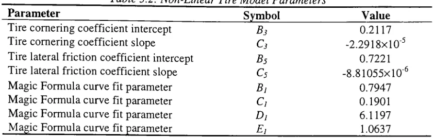
Table 3.2: Non-LinearTire Model Parameters
Parameter
Symbol ValueTirecorneringcoefficient intercept
B3
0.2117Tirecorneringcoefficient slope
C3
Tire lateralfrictioncoefficientintercept
B5
0.7221Tirelateral frictioncoefficient slope
c5
Magic Formulacurvefitparameter
Bi
0.7947MagicFormulacurvefitparameter
c,
0.1901Magic Formulacurvefitparameter
Dj
6.1197MagicFormulacurvefitparameter
E,
1.0637Now that thecornering coefficientandlateral frictioncoefficient are knownat
each
load,
thenormalized slipangle, a, canbecalculated at each datapointfrom the formula_
Ctania)
a =
Similarly,
thenormalizedlateralforce,
Fy
, at eachdatapoint is(3.6)
MVFZ
(3.7)
Whenthenormalized lateral force is plottedagainstthe normalizedslip angleforeach
vertical
load,
theresults lieon a single curve as shownin Figure 3.6. Thisnormalizeddata is then curvefit. Thereare a number of methods usedtofitthisdata. This model
uses a popularfunction knownasthe"magic formula". Themagic
formula,
as you willsee, isa combination oftrigonometricfunctionsandhasthe capabilitytoaccurately fit
u
o
03
<U N
1_ O
1.2
1
0.8
0.6
0.4
0.2
0
?
|
? 1779 N;OfifiQ M
A 3559 N
x 4448 Nl
X 5338 N
2 3 4
Normalized
Slip
AngleFigure 3.6: Tire Normalized Lateral Force
Thenormalizedlateral force is fitto thefunction
Fy
=D,sin(e)where
6 =C]atan(Bly/)
and
W
=(l-E,)a
+E^atan{Bxa)
B
(3.8)
(3.9)
(3.10)
Theparameters
Bj, C],Dj,
andE}
mustbe determinedtoprovidethebest fit to thenormalized experimentaldata. Thecurve
fitting
is implemented inthe MATLABscriptfileand uses theMATLAB OptimizationToolboxfunction
LEASTSQ
todo a non-linearleastsquares fit. The
LEASTSQ
function callsthefunction MAGICERROR.mthatcomputes theerrorsbetween eachdatapoint andthe curvefit function. Theparameters
B\,
C\,D\,
andE\
arefoundtominimize the sum ofthesquares ofthese errors.The filesMAGICFIT.m andMAGICERROR.m weredeveloped
by
Joseph KieferforuseinModeling
of Road Vehicle LateralDynamics.19
They
arelisted in Appendix A.l andAppendix
A.2,
respectively. Values forthe curvefitparameters are givenin Table3.2,
andthefunction isplottedin Figure 3.6 along withthenormalizeddata. As you can
clearlyseefromtheplot,an excellentfitto thedata had been obtained.
Nowthatafunction forthenormalized lateralforce interms of normalizedslip
angle is available,the tirelateral force canbecalculated for anycombination of vertical
loadand slipangle.
First,
thecornering coefficient and lateral frictioncoefficient arecalculatedfromthevertical load using Eq.
(3.3)
and (3.5).Second,
the normalizedslipangleis calculatedfromtheslipangle, thecorneringcoefficient, andthelateral friction
coefficientusing Eq. (3.6).
Next,
the normalizedlateral forceiscalculatedfromthenormalizedslipangleusing Eq.
(3.10),
(3.9),
and(3.8)
inthisorder.Finally,
the tirelateral forcecanthenbe found from thenormalizedlateral
force,
thelateral frictioncoefficient, andthe vertical loadas
F>=FyfiyFz
(3-11)
outputsthelateral force. Plotsoflateral force versusslipangle from thisfunction for
verticalloads of 1779
N, 2669N,
3559N,
4448N,
and5338 Nare shown in Figure 3.7 assolid linesalong withthe experimental datapoints.
Thenon-lineartire modelimplementedinthis section accuratelyreproduces the
experimentally determined lateral forceversusslip anglerelationshipofthe tireused in
this study. Thismodel iscapableofpredictingthelateral forceproduced
by
the tire athigh slip angles.
Thus,
the tiremodelis suitable for inclusion ina model of aircraftlateraldynamicswhere hightireslip angles are obtained. Whilethis tiremodelonly
determined lateral force due toslipangle, itcanbeextended topredict aligningmoment
dueto slip angle, lateral forceand aligningmomentduetocamber, andlongitudinal force
due tolongitudinal slip.
400 -i
350
-300
-250
-
g200-150
-a
2 100
-J
500-0 i
(
;
L
0
I 1 I I
? 1779 N
2669 N
A 3559 N
x 4448 N * 5338 N
Reconstructed i>* ^
ly* ^t^*"\
^^Jr^^T^
^X^
) 2 4 6 8 10 12 1
Slip
Angle4 16 18 2
3.5
Tire Model for Tail Wheel
Thetailwheelforthis studywas chosen tobe an8-V2 inch outerdiameter
by
3-inchwidth tire. Theinflationpressureis 40psi. Thismodel was also createdfrom data
provided
by
GoodyearTire & Rubber Company.Using
thedimensions ofthe tire,they
wereableto calculatethecorneringstiffness fora specifiedload. The datapoints were
thenplotted and acurvefitwasappliedusing theMICROSOFT EXCEL function
TRENDLINE. Thisfunctioncalculatesaleastsquaresfitthroughthe datapoints. A
fourthorder polynomial was fitto thedatapoints as shownin Figure 3.8. Theequation
EXCELusedtofitthedatapointsis displayed in thefigure. Alsoshown istheR-Squared
value. The R-Squared value canbe interpretedas theproportion ofthe variancein y
attributableto the varianceinx. This function returns thePearson product moment
correlationcoefficient,r, whichis adimensionless indexthat ranges from -1.0 to 1.0
inclusiveand reflects the extent of alinear relationship between twodatasets. As you
cansee, theR-Squaredvalueforthiscurvefit is exactly 1.
Therefore,
the equation shownrepresents thebestpossiblefitto the data. Thetailwheel model isusedin Chapter 4
when calculatingtail wheel cornering stiffnessbasedonthefractionof weight on the tail
160
O) 140
CD o
7? 120
100 Cj) r 3= 80
CO
c 60
i_
CD
r 40
L.
o
O 20
0
I
-?
1
y=
2E-07x3
-0.0006X2
+0.551 9x+3.8856
R2=1
\
0 200 400 600 800 1000 1200
Vertical Load
(N)
1400 1600
Inthis chapter, we willbe
looking
at a simplified mathematical model of an aircraft.By
using acomputer generatedmodel we willbeableto varyall aspects ofthe aircraft. Thisis extremelyuseful forthis study inwhich we needtoexplorethedifference betweenatricyclegear aircraftandataildraggeraircraft. This model will
ultimately allow usto
develop
thebasic conceptsthatgovern theresponse ofthe aircraft and controlthe stability. Fromthese concepts we willbe abletopredictthemotion ofthe aircraftasitmovesalongtherunway regardless ofits configuration, as well as examine the stabilityofthe aircraft asit is in theprocess oftaking
off orlanding.This simplified representation ofthe aircraft,referredto as the "bicycle"model, is atwo degree-of-freedommodelthat isoften usedtoexaminethe lateralresponseof road vehicles. The model isaltered slightlytoreflectthegeometryoftheaircraft used inthis study. The model is developed in a generalformforataildraggeraircraft. Laterin this
chapter, youwill see thatonlyminorchangesto themodel are needed to makeit intoa
tricycle gear aircraft. As you willsee, thismodel greatlysimplifies an aircraft.
However,
through itsusewe caninvestigatethe effects of majordesignand operational parameters on theyawingandsideslippingmotionsthat determinethepathand attitude ofthe aircraft. Such parametersinclude tire properties,inertiaproperties, center ofgravityThischapter aims todescribethe twodegree-of-freedommodel in detail. To
accomplish this, each vitalcomponentoftheaircraft will be studied untilthe modelis
complete.
First,
we willstartwithjustthemainlanding
geartoseehow its locationaffects stability. Aftertheseresults have beenestablished, theverticaltail will be added
ontothemodeland thechangein theresponse will beexamined.
Finally,
the studywillconclude withtheaddition ofthe tailwheel to the model. Atthis point, we should
understand enough abouttheeffects of each component tobeable tomake reasonable
suggestionstoimprovethestabilityof ataildraggeraircraft.
4.2
Description
ofModel
Thetwodegree-of-freedommodel forthe taildraggeraircraft usedin thisstudy is
shownin Figure 4. 1. As itsname suggests,themodel is onlyconcerned withtwo typesof
variable motion: lateral velocity, v, andyawingvelocity, r. Theforward velocity, u, is
assumedtobe constant and shall bechosen
by
theuser. Thesingle tireshown representsthepairoftiresforwardofthecenter ofgravity foran aircraft with ataildragger
configuration. Thetail wheel shownisallowedto swivel.
However,
itcanbe locked intoplaceto create some stiffnessthatwill resultin alateral tireforce. Thevertical tailshown
willhavea significant contributionto themotion oftheaircraft. The longitudinal
alignment ofthecomponents ofthe aircraft showwhythis iscalleda
"bicycle"
T
"--^v
^
Figure4.1: Bicycle Model fora Taildragger Aircraft
On atypical vehicle,the distance fromthecenter ofthefronttiresto thecenter of
therear tiresis termed the wheelbase,L. This is also thecase with an aircraft. Forthis
particular model ofaircraft,the tail wheel is locatedalmost
directly
below theaerodynamic center ofthe verticaltail.
Assuming
thatthey
areboth in thesamelocationmass momentof
inertia,
Iu,
withits centerofgravity locatedadistance afromthecenterofthefronttireandadistance b fromthetail wheelandthe aerodynamiccenter ofthe
vertical tail.
Noticethatthefronttires on anaircraftare not capable ofrotatingabout thez-axis
as on acarortruck.
Therefore,
they
cannotbeconsideredas control inputs.Again,
thisgreatly simplifies themodel, as we need notconcern ourselveswith steer angles.
The coordinate systemusedto describethemotion ofthe aircraftisthe standard
SAE vehicle-fixed x-y-z coordinatesystem,whichtranslates and rotates withthe
aircraft.
~
Thex-axis ispositiveintheforward
direction,
they-axis ispositiveto theright, andthez-axisis positivedown into thepage as specified
by
the right-hand rule.The origin ofthecoordinate system isatthecenter ofgravity
(CG)
ofthe aircraft.Motion is onlypermittedinthex-yplane.
4.2.1
Assumptions
Therepresentation oftheaircraft as a
"bicycle"
modeltakesinto account several
simplifyingassumptions in additionto those previouslymentioned.
They
are:Constant aircraft parameters
(m,
Ia
a,b, L)
Constantaircraftforwardvelocity, u
Motion inx-yplaneonly (ignore vertical,rolling andpitchingmotions)
Aircraftisrigid
Runway
surfaceis smoothIgnore lateral gravityeffects (ignore runwayslopein lateral
direction)
Ignorelongitudinal gravityeffects (ignore
runwayslopein longitudinal
direction)
Ignoreall
longitudinal
forces (tiredriving/braking
forces,
tirerollingresistance,aerodynamic
drag)
Ignorefront
landing
gearsuspension systemkinematics anddynamicsIgnoretireslipangles resultingfrom lateraltirescrub
Ignore lateral andlongitudinalloadtransfer(verticaltireforces remainconstant)
Tirepropertiesare independent oftimeand forward velocity
Ignore tirelateral forces due tocamber, conicity,andplysteer
Ignore tirealigning moments
Ignoreeffects oflongitudinal slipontire lateral force
Ignore tiredynamics (no
delay
in lateral forcegeneration)Ignore tiredeflections
4.2.2 Aircraft Parameters
The nominal values ofthe aircraft parameters usedforthe two degree-of-freedom
modelinthisstudy are given in Table 4. 1. Allparameters were obtainedthrough direct
measurements onthe aircraft, exceptforthemass andthe CG
location,
which canbeis 13.6-16.8 inches fromthedatum. As a point of referenceforthe reader, the forward
mostCGposition of 13.6inches fromthe datumwaschosento measure thecenterof
gravityparameters, a and
b,
givenin Table 4.1. These distances canthenbeusedtocalculatethefractionof weighton thefrontaxle,/. The SIsystem of units isusedforall
calculations. Theunit oflengthisthemeter
(m),
andtheunitoftimeis the second(s).Force ismeasured inthederivedunitNewton (N). Theseparameters are representative of
a production aircraft.
Table4.1: Vehicle Parameters
Parameter Symbol Value
AircraftMass m 748
kg
Yaw MomentofInertia I- 1760kg-m2
Wheelbase L 4.52m
Distance from CGto Front
Landing
Gear a 0.599 mDistance from CGto Aerodynamic CenterofVertical Tail
& Tail Wheel b 3.92 m
Front
Landing
Gear Weight Fractionf
0.867CG Limits CG 13.6-16.8 in
Vertical Tail Area
K
0.693m2CoefficientofLifton Vertical Tail
CLv
0.100/deg
4.2.3
Free
Body
Diagram
Due to the simplifyingassumptionsin Section
4.2.1,
therearefourtypes ofexternal forces actingontheaircraftin thex-yplanethat are consideredin thismodel:
fronttire lateral
force,
tail wheel lateralforce,
verticaltailforce,
and adisturbance input.Thefronttirelateral
force,
Fyjr0nt-tire,
occurs dueto tireslipangles asdoesthe tailwheellateral
force,
Fy_taii.wfieei- The vertical tailforce, Fy_,au,
isafunctionoftherelative airFy_disturbance,
is aninputthatacts atthe aerodynamic center oftheverticaltail, as doesthetailforce. Themostcommondisturbance input isa crosswindencounteredon the
runway. Theseforcesare shownactingonthevehiclein Figure 4.2 and areconsidered
positive when acting inthepositivey-direction.
T
"^disturbance
t
fc^ia
"y_front-m*av
y_tail
Figure4.2: Free
Body
Diagram4.3
Derivation
ofEquations
ofMotion
Theequationsofmotion will be developed forthe"bicycle" model. To dothis we
use basicprinciples ofNewtonianmechanics forrigid
body
motion relativetotranslating
androtatingcoordinatesystems.26
This is alinearmodel with twodegrees-of-freedom
which enablesthecalculation ofthemotion variables as afunctionofthe forcesand
moments actingontheaircraft.
Referring
toFigure 4. 1, themotion variables ofinterestareforwardvelocity, u, lateral velocity,v, and yawrate, r. Yaw rate, r, isthe angular
velocityoftheaircraftarounda vertical axispassingthrough theCG. Thevector sum of
u and vis thepath velocity, V. Thex-axisofthe aircraft is at a
body
slip angle,/?,
with VForstraight-ahead motion/J=0. Thetotal sideforce is Yandthe
yawingmoment about
theCG is N.
The reference axis system(aircraftaxis system) is fixedon theaircraft with the
origin attheaircraftCG (referto section4.2). The fundamental features ofthissystem
are thatchanges inthedependentvariables are measured relativeto inertial space andthe
moments and products ofinertiaare constant. Iftheactual path ofthevehicle relativeto
theground isrequired,an additional earth-fixed referencesystem isrequired.
Therigid
body
equations are obtainedfrom Newton's Second Law. Thisstatesthatthesummationof all external forces actingon a
body
is equalto the time rate ofchange ofthe momentumofthe body.
Furthermore,
the summation oftheexternalmoments actingonthe
body
is equalto the timerate of change ofthemoment ofmomentumare referredtoan absolute orinertialreferenceframe. Newton's Second Law
can beexpressedinthe
following
vectorequations:Yf=-g
dt
(4.1)
Ym=-h
^
dt
whereF andMaretheexternalforcesand moments (in vector
form)
actingaboutthecenterofgravity, andGandHarethe linearand angular momenta ofthe
body
(also invectorform). Theassumptions ofthemodel allow us toreduceEq.
(4.1)
sinceonlymotion inthex-yplane isconsidered and all longitudinal
(x-direction)
forces areneglected.
Thus,
we are left withSFv
=may
^
.(4-2)
Since thex-y-z coordinate systemis fixedto the aircraft with its origin atthe
aircraft center ofgravity, the translational velocityoftheaircraft mass center and
rotational velocityoftheaircraftare identicalto thoseofthex-y-zsystem. From Figure
4. 1, the velocity,
V,
oftheorigin ofthex-y-zsystem isV=m+vj
(4.3)
andthe angularvelocity,
Q,
isQ.= rk
Sincethex-y-zsystemis alsorotating, theunit vectors arechangingwithtime.
Thus,
theacceleration,a, oftheorigin expressedinan inertialreference framecoincident with the
x-y-zsystemis
dV a =
+
QxV
(4.5)
dt
= (u-vr)i+
(v
+wr)j
Likewise,
the angular accelerationofthex-y-z system relativeto aninertial referenceframeis
n= da
dt xyz
+Q.XQ.
(4.6)
Thus,
because we areonlyconcerned with lateralmotion, theacceleration values ofinterest are
a =v+ur
(4.7)
n.
=rThesevalues applytoboth theaircraft-fixedx-y-z system andtothe aircraft center of
gravity.
Theexternal forces actingonthevehicle are shown in Figure 4.2. The sum ofthe
forcesin they-direction andthesum ofthemoments aboutthez-axis canthen bewritten
as
/ , "
v * y_front-lire y_disturbance y
_tail y_tail-wheel
(4.8)
V A/f n*F -h*F +h*(F +F )
j1Y1
,
" '
y_front-tire y_disturbance ^ y
Substitution ofEq.
(4.7)
andEq.(4.8)
intoEq
(4.2)
yieldsthe equationsof motionforthe two degree-of-freedomtaildraggeraircraft:
y_front-lire + y_disturbance ~^y_tail ~ *'
y_tail-wheei
=m\V+Ur
)
a* F h* F A-h*( F 4- F \ J r
y_front-tire u L y_disturbance ~
u \r
y_ta.il ^*
y_tail-wheel'
~ l zz'
Hereuis thevehicleforward velocityand isconstant. The state variables arethe lateral
velocity,v, andtheyaw velocity, r.
Fyjront.tire
isthefronttirelateralforce, Fy__isturbance
isthedisturbance
input,
Fy_taa
isthe vertical tailforce,
andFy_tau.wheei
isthe tail wheel lateralforce.
Asstated,theaircraft system derived in Eq.
(4.9)
is atwo degree-of-freedomsystem. This is theminimum number ofindependentcoordinates neededto describe the
motion ofthe system.
Furthermore,
Eq.(4.9)
is a constraint equation. A systeminwhichtheconstraints are functionsofthecoordinates or coordinates and timeiscalled
holonomic. In manycasestheconstraint equations relatethe velocities orthevelocities
and coordinates. Ifthese equations canbe integratedto yield relations
involving
coordinates andtime only, the system isstill
holonomic.27
However,
the systemmay notbe holonomic intheevent oflarge displacements
during
integration. Sinceeachintegration step inthis study is small,the system remainsholonomic.
4.4
Derivation
ofTire
Slip
Angles &
Vertical Tail
Angle
From Chapter
3,
thelateral forceproducedby
atiredependsuponthevertical loadvelocityand angular velocity. Forthis reason,we must