A methodology for assessing the feasibility
of producing components by flow forming
Daniele MARINIa,1, David CUNNINGHAMa and Jonathan R. CORNEYa,2 aDepartment of Design, Manufacture & Engineering Management (DMEM),
University of Strathclyde,75 Montrose St, Glasgow G1 1XJ, UK.
Abstract. This paper describes a methodology for assessing the applicability of the flow forming process for the manufacture of specific components. The process starts by filtering potential candidates for flow forming from a component collection (e.g. company catalogue) and then carries out a detailed assessment of quantitative, technological and economic feasibility before determining a viable process plan. The process described uses analytical relationships and empirical criteria drawn from the literature.. A process time model (based on an analogy with CNC turning) is used to develop a hybrid cost model in order to evaluate economic feasibility. The paper concluded with a brief summary of the results of applying the process to an industrial case study.
Keywords: Flow forming, process modelling, analytical prediction, cost model, manufacturing framework, feasibility methodology
1. Introduction
Essentially flow forming is a deformation process carried out by rollers that compresses and stretches a blank (called a preform) over a rotating mandrel, usually in a number of consecutive stages. The appearance of heavy duty CNC flow forming machines has provided both the capability to fulfill small-medium batches and a flexibility which allows production of a wide range of rotational shapes and near-net-shape components. The process is very efficient in terms of material usage and its adoption often allows reduction of component’s weight and costs (both important considerations in many industrial applications) [1].
Investigations into flow forming are frequently connected to the manufacture of near-net-shape parts that are finished using traditional machining. The avoidance, or at least the minimization, of machining and raw materials can be delivered by the adoption of flow forming of technology but only if applied to appropriate components.
Thus a flow forming feasibility assessment methodology is critical to allow evaluation of how easy, or difficult, it is to produce a component with this cold forming technology. Steps of the feasibility assessment methodology are:
1. Find potential products were flow forming could be used.
2. Design a nominal flow forming process (e.g. specify a sequence of reduction ratios) for the candidate components.
1
3. Establish the feasibility (technological, qualitative and economic) for the production of the components, selected in step 1, by considering:
a. Technological feasibility: verifying if it is possible to realize a specific component using current flow forming technology.
b. Quantitative feasibility: analyzing theoretically the final proprieties of flow formed product.
c. Economic feasibility: evaluate the cost and lead-time of flow forming designed processes.
4. Explore variations on the nominal process plan generated in Step 2 to identify the one that is most likely to produce the required quality of product.
2. Flow Forming Feasibility Methodology
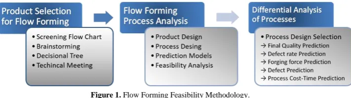
[image:2.595.125.481.364.464.2]The proposed flow forming methodology is composed of three main parts (Figure 2) that can be characterized as: Product selection, Process analysis and Differential analysis.
Figure 1. Flow Forming Feasibility Methodology.
The product selection step identifies potential products from a large number of candidate components (catalogues or assemblies), using high level criteria. This permitted a selection of components in which the flow forming manufacturing process could result in added value in term of, say, quality enhancement and/or savings.
The manufacturability analysis requires both component dimensions and a process design. For the components that reach the final step of the feasibility assessment number of different potential flow forming process plans are developed for every part, in order to evaluate alternative forming strategies. A geometric representation of each component is used to provide the dimensions needed to allow selection of the most appropriate process plan. The quality targets incorporated in the system described here are the final material strength and the surface finish. Manufacturing cost and time have been developed via an industrial case study that provides information for a hybrid cost model.
depending on the target requirements. The following sections now describe each step shown in Figure 1 in more detail:
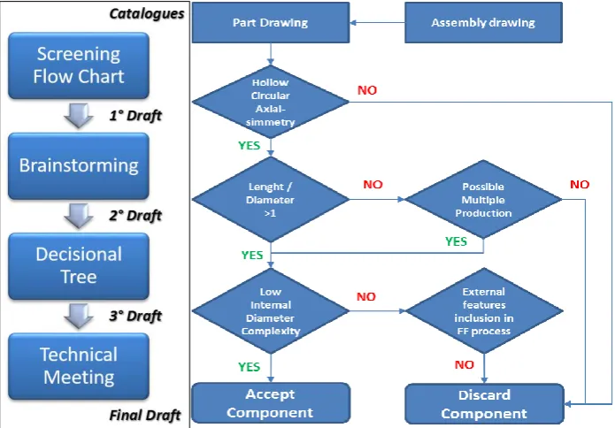
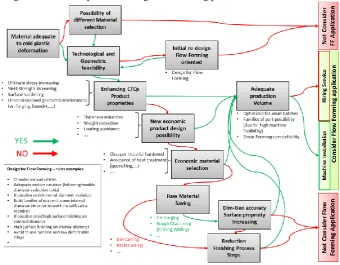
[image:3.595.125.473.352.594.2]Product selection procedure is based on four stages (Figure 2). Initial screening flow chart (Figure 2): enables high level filtering of components to identify potential candidates for further investigation. The flowchart assess the main geometric constrains for flow forming applications (e.g. hollow circular axial symmetry and length and diameter ratio) while taking into account near net shape considerations (low internal complexity). Stacked production (i.e. the formation of several components from one preform) has been considered as alternative for uneconomic batches of one. Brainstorming: reduces further forming candidates and includes unconsidered components. Decisional Tree (Figure 4): synthesis of acquired knowledge (i.e. literature and industrial applications) through critical flow forming application features identification. It investigates the initial material selection, technological and geometrical constrains, production volume and possible benefits related to flow forming application, in order to evaluate the initial feasibility of the process. Technical Meeting: discussion with production facilities or process expert about previous decisions (i.e. decisional tree developments).
Figure 2. Product selection procedure chart (left).Flowchart for flow forming product screening (right).
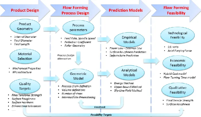
Process analysis has been defined by four phases (Figure 4): product design, flow forming process design, prediction models and flow forming feasibility.
Nominal Process Design Feasibility In this phase, the final component’s geometry and material selection are considered. The first is fundamental for designing the forming steps, while the latter has an enormous influence on the overall process definition (i.e. process parameters and intermediate forming steps).
been based on literature and industrial examples. A geometric modeling method (i.e. using volume constancy) is used to select suitable intermediate dimension for every designed reduction step in a multistage flow forming process.
Figure 4. Decisional tree for flow forming product selection.
Prediction Models. Using empirical models, the defect rate, ultimate tensile strength and surface finish, can be deducted. Key to this process is the S/L ratio, developed Gur and Tirosh [2] and validated by several authors, expresses plastic flow quality for given process parameters. If axial contact length (L) exceeds the circumferential length (S), circumferential plastic flow dominates (S/L<1) and geometrical inaccuracies and defects are common [1]. Hollomon's power law [3,4] and Erasmus law [5] are deployed by authors for predicting the ultimate strength of formed components and shows good agreement with experimental data (particularly the latter one). [6] develop an empirical formula for flow forming, evaluating the surface finishing. Using such analytical models, working forces and powers can be deducted, using component and roller geometries, materials and process parameters. Three main analytical models have been proposed in the literature: energy model [7]–[9], upper-bound method [10] and slip-line field [11]. Energy is the most frequently applied and developed by researchers so it has been applied in the case studies reported here. This phase also provide also feedback to the process parameters and the intermediate process steps. Different combination of process should be needed for obtaining a suitable flow forming sequence.
based on industrial case studies. Flow forming costs and lead-times can be compared with current process parameters. Some idle times and setup costs are also inferred from similar and dual cases (e.g. CNC machine set-up). Forming powers (i.e. analytically calculated in the previous phase) have been used for calculating energy expenditures during the flow forming process.
[image:5.595.124.475.309.514.2]Comparative Analysis of Process Plans. Depending on the quality target, the designed flow forming process alternatives can be compared for defining the target optimal solution. Although, flow forming designs must be filtered for the defined technological feasibility (i.e. the upper limit of forming forces and the S/L threshold) and after evaluate qualitative (S/L threshold, UTS increasing threshold, surface roughness acceptable limit) and economic feasibilities. A weighted average of these different parameters can be realized, for summarizing the comparison between different flow forming process plans (i.e. sequences of reduction operations).
Figure 4. Flow forming process analysis chart.
3. Case Studies
Products from Weir Group PLC have been used for investigating the flow forming feasibility. Product selection has been applied on assemblies and catalogues. After filtering with the flow chart (Figure 3), 27 components were selected. Brainstorming reduce them to 5, mainly due to the repetition of certain components in the assemblies. Decisional tree reduced them to 2: a riser pipe and valve seat.
Similarly a flow forming process for a valve seat was designed to be produced in a stack (i.e. 4, 6 or 8 from the same preform) with a proportional increasing of forming steps. Technologically, the process was deemed acceptable for many combinations. Although ultimate strength and surface roughness have been considered as acceptable as well as the lead time (i.e. almost halved), the cost has doubled in comparison with the current cost (based on forging and machining).
4. Conclusion
This methodology provides a reliable guidance for finding opportunities an evaluating the feasibility of flow forming process. Although the analytical model can formulate the process in a complete way, they are not sufficient for analyzing completely the flow forming process. Process parameters and design selection should interact directly with the feasibility study, giving an immediate feedback and not acting as hypothesis. A more complete framework should be developed in this sense, including numerical capabilities and approaches.
Acknowledgements
The authors want to thank WARC (Weir Advanced Research Centre), Weir Group PLC and DMEM of the Strathclyde University of Glasgow for the fundamental and continuous support in this research.
References
[1] D. Marini, D. Cunningham, and J. R. Corney, “A review of flow forming processes and mechanisms,” in Key Engineering Materials, vol. 651–653,, Eds. 2015, pp. 750–758.
[2] M. Gur and J. Tirosh, “Plastic flow instability under compressive loading during shear spinning process,” J. Eng. Ind. ASME, 104, pp. 17–22, 1982.
[3] B. Podder, C. Mondal, K. R. Kumar, and D. R. Yadav, “Effect of preform heat treatment on the flow formability and mechanical properties of AISI4340 steel,” M.Des., vol. 37, pp. 174–181, 2012. [4] A. Jalali Aghchai, N. a. Razani, and B. Mollaei Dariani, “Flow forming optimization based on
diametral growth using finite element method and response surface methodology,” Proc. Inst.
Mech. Eng. Part B J. Eng. Manuf., vol. 226, no. 12, pp. 2002–2012, Oct. 2012.
[5] K. M. Rajan, P. U. Deshpande, and K. Narasimhan, “Effect of heat treatement of preform on the mechanical propieties of flow formed AISI 4130 - a theoretical an experimental assessment,” J.
Manuf. Process. Technol., vol. 126, 2002.
[6] K. M. Rajan and K. Narasimhan, “An Investigation of the Development of Defects During Flow Forming of High Strength Thin Wall Steel Tubes,” Pr. Fail.Anal., vol. 1, pp. 69–76, 2001. [7] M. Hayama and H. Kudo, “Experimental Study of Tube Spinning,” Bullettin JSME, vol. 22, no.
167, pp. 769–775, 1979.
[8] M. Hayama and H. Kudo, “Analysis of Diametral Growth and Working Forces in Tube Spinning,”
Bullettin JSME, vol. 22, no. 167, pp. 776–784, 1979.
[9] S. S. Jolly and D. S. Bedi, “Analysis of Power and Forces in the Making of Long Tubes in Hard-to-Work Materials,” Proc. World Congr. Eng., vol. II, 2010.
[10] J.-W. Park, Y.-H. Kim, and W.-B. Bae, “Analysis of tube-spinning processes by the upper-bound stream-function method,” J. Mater. Process. Technol., vol. 66, no. 1–3, pp. 195–203, Apr. 1997. [11] H. N. Nagarajan, H. Kotrappa, C. Mallanna, and V. C. Venkatesh, “Mechanics of Flow Forming,”
CIRP Ann. - Manuf. Technol., vol. 30, no. 1, pp. 159–162, Jan. 1981.