International Journal of Innovative Technology and Exploring Engineering (IJITEE) ISSN: 2278-3075, Volume-8, Issue- 6S4, April 2019
Abstract—This paper commences an exalted control scenario for Wind Energy Systems(WES) adopting Doubly Cater Induction Generator (DCIG) . A vigorous Ant Lion Optimizer(ALO) technique is assented with a Fractional Order PI assessor to optimize the powers and to lift the aggressive performance of WES[2][3]. The enforcement and adequacy of ALOFOPI assessor shows amusing countenance in terms of blather devaluation confined concurrence time and hefty against specifications[1]. The proposed ALOFOPI algorithm shows a great convergence and enhanced stability.
Keywords: Wind Energy Systems(WES),Doubly Cater Induction Generator(DCIG), Ant Lion Optimizer(ALO), Fractional Order PI assessor(FOPI), PI assessor.
I. INTRODUCTION
As Wind Energy(WE) is a continual reserve with no ammunition charge and no consumptive debate gases and are originated consequently[3]. WE is the backup for exploring and evolution of power generation. The wind is an innate development against many causes allying clime disparities, barometrical pressures and the earth radiation fogs. The above mentioned aspects invent the wind acceleration and potential for electrical power generation. WE is reformed into electrical energy by employing Wind Turbine(WT) they novitiate driving force to electromotive force. In this we study about the control entities in DCIG,constates the main stream contours for the WT in the exploring exertions.
This paper is reorganized as proceeds in part I depicts about the WES [3]firmness to the yield potential from wind, the power coefficient(C0) and the Tip Speed Ratio Characteristic[3]. DCIG exemplary and the curb strategy is accustomed by a PI assessor in part II [3]and mutated PI assessors in part III and IV respectively[4]. And part V is counterfeit results with matlab Simulink model and final cessation in part VI.
PartI Wind Energy System(WES):
Revised Manuscript Received on April 12, 2019.
M.Vasavi Uma Maheswari,Asst Professor EEE DepartmentCollege of Engineering & Technology AcharyaNagarjuna University Guntur,Andhra Pradesh.T.N, India. ([email protected])
P.V.RamanaRao,Professor EEE Department College of Engineering & Technology AcharyaNagarjuna University Guntur, Andhra PradeshT.N, India. ([email protected])
S.V. Jayaram Kumar,Professor EEE Department College of Engineering, JNTUHHyderabad. Telangana, T.N, India.
Fig1:Block diagram of DCIG system
WES will metamorphose the dynamic vitality into automa ted vitality by WT blades and yet novitiates to the electrical vitality through a dynamo. The WT based on DCIG scheme is given in fig1. The vitality originated form the WT’s depends on the velocity of wind speeds. At flat wind speeds the WT cannote provoke electrical vitality i.e for (1-3)m/s. At wind speeds in the midst (2-5)m/s the WT’s will start calling i.e ‘Cut-in-wind-speed’. At the wind speeds in the midst of (12-15)m/s is termed as the ‘nominal or rated wind speed’, where WT’s employing on their full spectrum. At huge wind speeds that are over 25m/s, the WT will be hampered i.e , because huge wind speeds may deteriorate the mechanics of the WT’s. The gain of WT is dependent on the power coefficient Co. It is given by
𝑷ɱ =𝟏
𝟐þ𝝅𝜰
𝟐ᶌ𝟑 𝑪о − − − − − −(𝟏)
And the tip speed ratio is constructed as
Г =Ѡᵣ𝜸
ᶌ − − − − − − − − − (𝟐)
Þ- is the air density (kg/m3), ᶌ- is velocity of wind speed m/s, Ѡᵣ − is the turbine speed, 𝐶о −power coefficient and Ḃ- is the pitch angle.
𝑪о Г, Ḃ = 𝒄𝟏 𝒄𝟐
Г𝒊− 𝑪𝟑Ḃ − 𝑪𝟒 𝒆
𝒄𝟓
Г𝒊 + 𝑪𝟔 − − (𝟑)
Active and Reactive Powr Control of Dcig
Wind Power System using Evolutionary
Algorithm Based Fraction Order Controllers.
Order Controllers
In which
𝟏 Г𝒊=
𝟏
Г + 𝟎. 𝟎𝟖Ḃ − 𝟎. 𝟎𝟑𝟓
Ḃᶾ + 𝟏 − − − − − − − − − (𝟒)
The above parameters depends on the shape of the blade and its aerodynamic consummation. Fig2 shows the affinity among (𝐶о 𝑎𝑛𝑑 Г)
Fig2: plot between Lambda and Power coefficient
Part II DCIG system:
DCIG consist of WRIG ( wound rotor Induction Generator) and an AC/DC/AC IGBT-placed PWM converter. All electrical valuables and criterions and accredit to the stator as show below in fig3
AC
AC
Rs WΦqs Xs
Rr Xr
Lm Vqr
Vqs
(W-Wr)Φqr
AC
AC
Rs WΦds Xs Rr Xr
Lm Vdr Vds
(W-Wr)Φdr
Iqs Iqr
Ids Idr
Fig3&4: proportionate equivalent circuit of DCIG Q-axis and D-Q-axis parameters
The electrical equation of DCIG in the proportionate circuit shown in fig3 and fig4 from the Park’s Transformation are given below[2][3]
𝑽𝒅𝒔 = 𝑹𝒔 𝑰𝒅𝒔 + 𝒅
𝒅𝒕 ∅𝒅𝒔 − 𝑾𝒔 ∅𝒒𝒔 − − − − − (𝟓)
𝑽𝒒𝒔 = 𝑹𝒔𝑰𝒒𝒔 + 𝒅
𝒅𝒕∅𝒅𝒓 + 𝑾𝒔 ∅𝒅𝒔 − − − −(𝟔)
𝑽𝒅𝒓 = 𝑹𝒓 + 𝒅
𝒅𝒕∅𝒅𝒓 − 𝑾𝒔 − 𝑾 ∅𝒒𝒓 − −(𝟕)
𝑽𝒒𝒓 = 𝑹𝒓 +𝒅
𝒅𝒕∅𝒒𝒓 + 𝑾𝒔 − 𝑾 ∅𝒅𝒓 − − − (𝟖)
Likewise the stator flux can be conveyed as
∅𝒅𝒓 = 𝑳𝒔𝑰𝒅𝒔 + 𝑳𝒎𝑰𝒅𝒓 − − − − − 𝟗
∅𝒒𝒓 = 𝑳𝒓𝑰𝒒𝒓 + 𝑳𝒎𝑰𝒒𝒔 − − − − − −(𝟏𝟎)
Where RsRrLsLr acts as resistances and leakage reactance’s of both stator and rotor windings and Lm acts as mutual inductance and W-is the rotor speed.
Likewise Vds ,Vdr, Vqs, Vq,r Ids, Idr, Iqs ,Idr, ɸds, ɸdr, ɸqs, ɸqr acts as the direct and quadrature peripherals of the space phasors of the stator and rotor voltage , current and flux ingredients.
The active and reactive competencies at the stator and rotor are defined as
𝑃𝑠 = 𝑉𝑑𝑠 𝐼𝑑𝑠 + 𝑉𝑞𝑠 𝐼𝑞𝑠 − − − − − − − − − −(11)
𝑄𝑠 = 𝑉𝑞𝑠𝐼𝑑𝑠 − 𝑉𝑑𝑠 𝐼𝑞𝑠 − − − − − − − − − −(12)
𝑃𝑟 = 𝑉𝑑𝑟 𝐼𝑑𝑟 + 𝑉𝑞𝑟 𝐼𝑞𝑟 − − − − − − − − − − 13
𝑄𝑟 = 𝑉𝑞𝑟𝐼𝑑𝑟 − 𝑉𝑑𝑟 𝐼𝑞𝑟 − − − − − − − − − −(14)
Eventually, the electromagnetic revolution is given as
𝑇𝑒 = 1.5𝑝 ∅𝑑𝑠 𝐼𝑞𝑠 − ∅𝑞𝑠𝐼𝑑𝑠 − − − − − − − 15
𝑤𝑒𝑟𝑒(𝑝 − 𝑝𝑜𝑙𝑒𝑝𝑎𝑖𝑟𝑠)
II. CONTROL STRATAGEM& RESULTS: An exemplary design of a PI Assessor system is shown in fig 4 below from which the PI assessor is adopted to achieve the proportional and integral behavior of the resulting signals admixed and include to form the control signal u(t) enforced with the plant model. A mathematical depiction of the PI assessor is
𝒖(𝒕) = (𝑲𝒑[𝒆 𝒕 + 𝟏
𝑻𝒊 𝒆 𝒕 𝒅𝑻 𝑼𝒑 𝒕 + 𝑼𝒊 𝒕 𝟏𝟔
𝒘𝒉𝒆𝒓𝒆 𝑲𝒑 − 𝑷𝒓𝒐𝒑𝒐𝒕𝒊𝒐𝒏𝒂𝒍 𝒈𝒂𝒊𝒏 , 𝑻𝒊
− 𝒊𝒏𝒕𝒆𝒈𝒓𝒂𝒍 𝒕𝒊𝒎𝒆 𝒄𝒐𝒏𝒔𝒕𝒂𝒏𝒕 𝒐𝒇 𝑷𝑰 𝒂𝒔𝒔𝒆𝒔𝒔𝒐𝒓, 𝒆 𝒕 − 𝒆𝒓𝒓𝒐𝒓 𝒔𝒊𝒈𝒏𝒂, 𝒖 𝒕 − 𝒊𝒏𝒑𝒖𝒕 𝒔𝒊𝒈𝒏𝒂𝒍 = 𝒓 𝒕 − 𝒚 𝒕
As PI assessors are most recurrently used in which an assessor without Differentiator(D) mode is used during (i) rapid feedback is not enforced (ii) Huge dis orders and turbulences are begun during action of the mean process of assessors(iii) There is only one vitality storage in means (iv) there are huge transit bind in the structure or arrangement.
PI Assessor Plant Model
International Journal of Innovative Technology and Exploring Engineering (IJITEE) ISSN: 2278-3075, Volume-8, Issue- 6S4, April 2019
Tem
Stator flux Estimator
Lm/Ls
Rotor current
Q ref
Q measure
PI assessor
X X
÷ Idref ±
Id
Iq
PI assessor
± Iq ref
±
[image:3.595.53.281.47.428.2]Vrotor
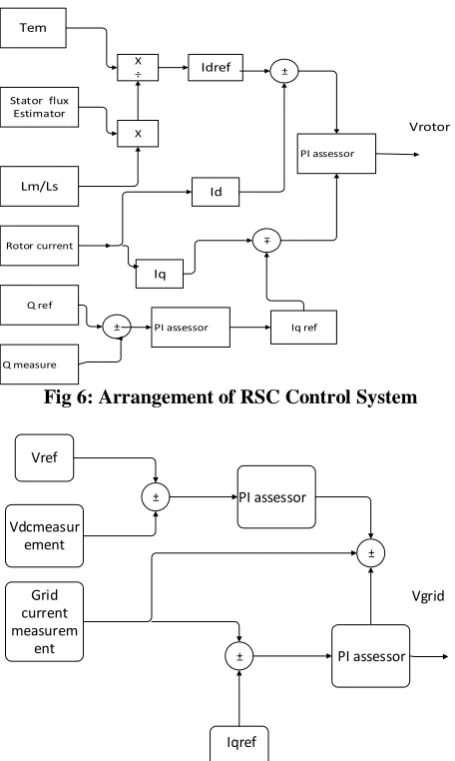
Fig 6: Arrangement of RSC Control System
Vref
Vdcmeasur ement
Grid current measurem
ent
PI assessor
Iqref
PI assessor
±
±
±
Vgrid
Fig 7: Arrangement of GSC control system
The above arrangements are with a typical PI assessor in which the typical PI assessor is replaced with FOPI assessorand ALOFOPI assessors.
FOPI Assessor:
From view of typical PI assessor an FOPI assessor abides much sophisticated attainment. It was popularized by Podlubny, who prospected a generalized PIλDμ. Adopting a ‘λ’ order integrator and ‘μ’order differentiator. He proven the excellence of the FOPID controllers than the typical PID controllers which have three tuning parameters[6]. The generic form of the translation action of the plant was
𝑃 𝑠 = 𝑘
𝑇𝑠 + 1− − − − − − − (16)
where T and K are constants. In this sector, two distinct assessors are discussed as ensures:
𝑪𝒑𝒊 𝒔 = 𝑲𝒑 𝟏 +𝑲𝒊
𝒔 − − − − 𝟏𝟕
𝑪𝒇𝒐𝒑𝒊 = 𝑲𝒑(𝟏 +𝑲𝒊
𝒔𝝀) − − − − − (𝟏𝟖)
Design Stipulation:
A tune method for PI assessorand FOPIassessor[6] is proposed. We adopt the gain crossover frequency, Wc and phase margin ɸm to be co equal for the pair of assessors. For
the system cohesion and vitality the following restraints are considered.
a)𝐴𝑟𝑔 𝑔 𝑗𝑤 = 𝐴𝑟𝑔 𝐶 𝑗𝑤𝑐 𝑃 𝑗𝑤𝑐 = ∠𝐶 𝑗𝑤𝑐 +
∠𝑃 𝑗𝑤𝑐 = −𝜋 + ∅𝑚Where G(jw) is the open loop
translation action of the system,c(jw) is the assessor translation action and P(jw) is the plant translation action. b) Gain cross over frequency restraint:
𝚰𝑮 𝒋𝒘 𝚰𝒅𝒃 = 𝚰𝑪 𝒋𝒘𝒄 𝑷 𝒋𝒘𝒄 𝚰𝒅𝒃 = 𝟎 − − − −(𝟏𝟗)
c)Vitality to loop yield variations which appeals that the Bode plot to be oblate at the Gain Cross over frequency Wc i.e. the derivative of the open loop phase at the gain cross over frequency to be level to zero
𝑑(𝐴𝑟𝑔[𝐺 𝑗𝑤𝑐 ]
𝑑𝑤 | = 0 𝑎𝑡 𝑤 = 𝑤𝑐 − − − − − −(20)
Fractional order PI assessor adopting:
A tune methodfor FOPI assessor is given below for the considered first order plant. The open loop translation action with FOPI assessor is[6]
𝐺 𝑠 = 𝐶𝑓𝑜𝑝𝑖 𝑠 𝑃 𝑠
= 𝐾𝑝 1 +
𝐾𝑖
𝑗𝑤 𝜆
𝐾
𝑇𝑠
+ 1
− −(21)
Where K and T are known and Kp,Ki and 𝜆 should be designed in the assessor design process. The FOPI assessor can be expressed as
𝑪𝒇𝒐𝒑𝒊 𝒔 = 𝑲𝒑 𝟏 +𝑲𝒊
𝒔𝝀 = 𝑲𝒑 𝟏 +
𝑲𝒊
𝒋𝒘 𝝀 − − − (𝟐𝟐)
Modelling of ALOPI and ALOFOPI assessors:
Order Controllers
𝑿𝒊
= [ 𝟎; 𝒓(𝟏); 𝒓(𝟏)
+ 𝒓(𝟐); … … … . . ; 𝒓 𝒋 ; 𝒓 𝒋 𝑻
𝒋=𝟏 𝑻−𝟏
𝒊=𝟏
(𝟐𝟑)
Where i=1,……,dim, dim is the ant or ant lion tenuity, T is the maximal number of loops ,
𝑋 = 𝑋1; … … … … ; 𝑋𝑑𝑖𝑚 , 𝑋𝑖𝑖𝑠𝑎 𝑇 + 1 × 1𝑚𝑎𝑡𝑟𝑖𝑥and r(j) is an actuarial expansionand can be utteredas𝑟 = 1 𝑟𝑎𝑛𝑑 > 0.5 𝑜𝑟𝑒𝑙𝑠𝑒 − 1 𝑓𝑜𝑟𝑟𝑎𝑛𝑑 ≤ 0.5 where rand is a ergodic number beget with allocationdiscretionalin the range of (0,1). Discretionalwalks of ants need to be regenerates the location in actual search space according to curtailer and loftier bourne. It is diagnoized by
𝒀𝒊 =(𝑿𝒊 − 𝒂𝒊)
𝒃𝒊 − 𝒂𝒊 × 𝒅𝒊 − 𝒄𝒊 + 𝒄𝒊 − − − − − − − (𝟐𝟒)
ai and bi are the littlest and mostlest of Xi , Ci and di augur the littlest and mostlest of antlion in the ithtenuity severally respectively, 𝑌 = 𝑌1; … … … . 𝑌𝑑𝑖𝑚 , 𝑌𝑖 𝑖𝑠 𝑎 (𝑇 + 1) × 1𝑚𝑎𝑡𝑟𝑖𝑥,Xi is altered in the domain [0,1]
using (𝑋𝑖 −𝑎𝑖 )(𝑏𝑖 −𝑎𝑖 ). Then it is regenerated in the sphere [Ci di]
using eq(24). It dintthe anomaly aboutthe electant lion[1]. The antsincline are affected by antlions traps. This can be described as
𝐶 = 𝐶! + 𝐴𝑛𝑡𝑙𝑖𝑜𝑛
𝑑 = 𝑑! + 𝐴𝑛𝑡𝑙𝑖𝑜𝑛
c! and d! are the littlest and moistest of dynamic limits at current loop. Ant lion representthe rightant lion electby roulette , according to the fitness[1].
𝑪! = (𝒍𝒃) ÷ (𝟏𝟎𝝎× 𝒕
𝑻! ) = (𝒖𝒃) ÷ (𝟏𝟎𝝎 × 𝒕 𝑻! )
‘t’ is the current iteration and lb&ub are the lower and upper limits of the roulette . Andw-constant based on the current iteration.
𝑤 = 2 𝑡 > 0.1𝑇
𝑤 = 3 𝑡 > 0.5𝑇
𝑤 = 4 𝑡 > 0.75𝑇
𝑤 = 5 𝑡 > 0.9𝑇
𝑤 = 6 𝑡 > 0.95𝑇
Y is a (T+1) Xdim matrix deliberatedin the order of equation ………
The next step is to adopt elitism to the optimization. Where the pointof each ant depends on the stochasticaround an ant lion selected by the roulette and elite.
𝐴𝑛𝑡 =𝑅𝑎 + 𝑅𝑒
2 𝐴𝑛𝑡 𝑖𝑠 𝑡𝑒 𝑛𝑒𝑤 𝑝𝑜𝑠𝑖𝑡𝑖𝑜𝑛
Ra is the random walk around the ant lion selected by the roulette wheel, Re is the random walk around the Elite.
𝑨𝒏𝒕𝒍𝒊𝒐𝒏 = 𝒂𝒏𝒕, 𝒊𝒇 𝒇(𝑨𝒏𝒕) < 𝑓(𝐴𝑛𝑡 𝑙𝑖on
Generating Initial Values by Executing Tune Model
Calculating the fitness for each ant and ant lion and getting the
elite
Getting an Ant lion using RE
Updating lower & upper boundaries, random
walks around the identified antlion and
elite
Modifying the position of ant
Evaluate the
position of all
ants
Calculate the fitness of all ants
evaluating the ability of all ants
Modifying all antlions &
elite
Satisfying the end of criterion
Settling at the best solution A
A
B
[image:4.595.310.544.110.418.2]B
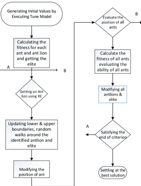
Fig 8: Flow chart for implementing the ALO stemmingrule
Part V Counterfeit Results:
International Journal of Innovative Technology and Exploring Engineering (IJITEE) ISSN: 2278-3075, Volume-8, Issue- 6S4, April 2019
Fig9: Collation of typicalPI,ALO-PI,FOPI,ALOFOPI assessors in generating the active power with a voltage
dip from 0.03 to 0.13 msec at source
Fig10: Collation of typicalPI,ALO-PI,FOPI,ALOFOPI assessors in generating there- active power with a
voltage dip from 0.03 to 0.13 msec at source
Fig11: Collation of typicalPI,ALO-PI,FOPI,ALOFOPI assessors in generating the active power with a voltage
dip from 0.03 to 0.13 msec at grid
Fig12: Collation of typicalPI,ALO-PI,FOPI,ALOFOPI assessors in generating the active power with a voltage
dip from 0.03 to 0.13 msec at grid
III. CONCLUSION:
From the simulation results the collated with typical PI controller the power outputs are enhanced with ALOFOPI controllers. It can uses various sizes model for study and monitoringadvanced strategies in future. From the results we can understand that the power output properties can yield much better even with various input velocities of the wind speeds.
REFERENCES:
1. SeyedaliMirjalili ‘The Ant Lion Optimizer’ Advances in engineering software.School of Information and Communication Technology, Griffith University, Nathan, Brisbane, QLD 4111, Australia Queensland Institute of Business and Technology, Mt Gravatt, Brisbane, QLD 4122, Australia.
2. T. Unchim and A. OonsivilaiA Study ofWind Speed Characteristic in PI Controller based DFIGWind Turbine World Academy of Science, Engineering and Technology International Journal of Electrical and Computer Vol:5, No:12, 2011.
3. An Improved Ant Lion Optimization Algorithm and Its Application in Hydraulic Turbine Governing System Parameter Identification TianTian 1, Changyu Liu 1,*, Qi Guo 2, Yi Yuan 2, Wei Li 2 and Qiurong Yan 3
4. Coordinated control of rotor and grid sides converters in DFIG based wind turbines for providing optimal reactive power support and voltage regulation Mohsen Rahimi Sustainable Energy Technologies and Assessments 20 (2017) 47–57.
5. Hansen,L.H.Helle L., Blaabjerg F., Ritchie E., Munk-Nielsen S.,Binder, H.Sorensen, P. and Bak—Jensen,B.,”conceptual survey of Generators and Power Electronics for Wind Turbines”,Rise National Laboratory, Roskilde, Denmark, Riso-R1205(EN),2001
6. Abdelaziz Azza1, Hamid Kherfane2,’ Robust Control of Doubly Fed Induction Generator Using Fractional Order Control’International Journal of Power Electronics and Drive System (IJPEDS) Vol. 9, No. 3, September 2018, pp.
1072~1080 ISSN: 2088-8694, DOI: