UNIVERSITI TEKNIKAL MALAYSIA MELAKA
VEHICLE SPEED CONTROL SYSTEM USING WIRELESS COMMUNICATION TECHNOLOGY
This report submitted in accordance with requirement of the Universiti Teknikal Malaysia Melaka (UTeM) for the Bachelor’s Degree in Electronic Engineering
Technology (Telecommunication) (Hons.)
by
MOHD AKMAL BIN MOHD SIDIK B071210313
901104025025
DECLARATION
I hereby, declared this report entitled “Vehicle Speed Control System Using Wireless Communication Technology” is the results of my own research except as cited in
references.
Signature : ……….
Author’s Name : MOHD AKMAL BIN MOHD SIDIK
APPROVAL
This report is submitted to the Faculty of Engineering Technology of UTeM as a partial fulfillment of the requirements for the degree of Bachelor of Engineering Technology (Telecommunication) (Hons.). The member of the supervisory is as follow:
i
ABSTRAK
ii
ABSTRACT
iii
DEDICATION
iv
ACKNOWLEDGEMENT
First and foremost, I would like to thank God for His blessing so that I am able to finish my bachelor degree project. I am using this opportunity to express my special appreciation and gratitude to everyone who supported me throughout the process of completing my final year project. I am thankful for their aspiring guidance and advice during this project.
I also want to express my warm thanks to my supervisor Puan Norain Binti Rahim for the support and encourage me toward my research. I would like to thank UTeM for allowed me to use the facilities in order to complete the research and also faculty lecture for advice and help.
v
TABLE OF CONTENT
Abstrak i
Abstract ii
Dedication iii
Acknowledgement iv
Table of Content v
List of Tables vii
List of Figures viii
List Abbreviations, Symbols and Nomenclatures ix
CHAPTER 1: INTRODUCTION 1
1.1 Background 1
1.2 Problem Statement 2
1.3 Objective 2
1.4 Scope of work 2
1.5 Thesis Layout 3
1.6 Summary 3
CHAPTER 2: LITERATURE REVIEW 4 2.1 Previous Project Research 4
2.2 Hardware Overview of System 9
2.2.1 Microcontroller 10
2.2.2 Arduino UNO 12
2.2.3 Raspberry Pi 14
2.2.4 Comparison between Arduino UNO and Raspberry Pi 14
2.2.5 Power Supply in Arduino 15
2.3 RF (Radio Frequency) 16
2.4 DC Motor 18
2.4.1 Brushless DC motor 18
vi
2.6 L298N Motor Driver 20
2.7 Summary 21
CHAPTER 3: METHODOLOGY 22
3.1 Introduction 22
3.2 Project Planning 22
3.3 Design of methodology 23
3.4 Hardware and Software Implementation 25
3.5 Project Analysis 30
3.6 Project Block Diagram 35
3.7 Summary 36
CHAPTER 4: RESULT & DISCUSSION 36
4.1 Hardware Implementation 36
4.2 Software Implementation 39
4.3 Summary 45
CHAPTER 5: CONCLUSION & RECOMMENDATION 46
5.1 Conclusion 46
5.2 Recommendation 47
REFERENCES 48
APPENDICES 51
A Project Planning 51
vii
LIST OF TABLES
2.1 2.2 2.3 2.4
Advantages of Arduino UNO
Comparison between Arduino UNO and Raspberry Pi Arduino UNO Power Supply pins description.
Features of Brushless DC Motor.
viii
LIST OF FIGURES
2.1(a)
2.1(b)
Flowchart scheme of operation in Normal Mode (kameswari, et al., December 2011).
Flowchart Schematics Operation in Active Mode (kameswari, et al., December 2011).
5
6
2.2 Flowchart of Process (Govindaraju, et al., August 2014). 8 2.3 Block Diagram of the circuit and operating mode (Nicolae &
Marcel, May 2014).
10
2.4 Block Diagram of Closed Loop DC Motor Speed Control System (Mondal, et al., 2013).
11
2.5 2.6
Arduino UNO circuit Raspberry Pi Circuit
12 14 2.7 Example of supply for Arduino UNO circuit (Barrett, June
2012).
15
2.8 Block Diagram of RF transmitter and receiver (STrobotix, et al., 2015).
16
2.9 Brushless Dc Motor 18
2.10 2.11
Red and Green LED L298N Circuit Diagram
20 21 3.1 3.2 3.3 3.4 3.5 3.6 3.7 3.8 3.9 3.10
Block Diagram of methodology implementation Project Flowchart
nRF24L01 module connecting to Arduino UNO Transmitter flowchart
Verify Symbol Receiver flowchart
Distance at 1 meter from transmitter Distance at 2 meter from transmitter Distance at 3 meter from transmitter Distance at 4 meter from transmitter
ix 3.11 3.12 3.13 3.14 3.15 3.16 3.17 3.18 4.1 4.2 4.3 4.4 4.5 4.6 4.7 4.8 4.9 4.10 4.11 4.12 4.13 4.14 5.1
Distance at 5 meter from transmitter Distance at 6 meter from transmitter Distance at 7 meter from transmitter Distance at 8 meter from transmitter Distance at 9 meter from transmitter Distance at 10 meter from transmitter
The graph of Signal Strength versus Distance Project Block Diagram
Serial Window in arduino UNO IDE Software for motor less than 40 Rotation per second.
Green LED ON
Serial Window in arduino UNO IDE Software for motor more than 40 Rotation per second.
Red LED ON
Green LED ON with Transmitter ON Green LED ON with Transmitter OFF
Vehicle speed control using wireless communication prototype. Radio in transmitter part
rxAddr for transmitter part Setup in the Transmitter part Loop sketching in transmitter part Serial in setup function
Character in the loop function Encoder Disc
40km/h speed signboard
x
LIST OF ABBREVIATIONS, SYMBOLS AND
NOMENCLATURE
AC - Alternating Current AVR - Aboriginal Voices Radio
DC - Direct Current
ECU - Electronic Control Units
GND - Ground
GPS - Global Positioning System GSM - Global System for Mobile
IR - Infrared
I/O - Input / Output
LED - Light Emitting Diode LCD - Liquid Crystal Display
MAX - Maximum
P - Proportional
PWM - Pulse Width Modulation RAM - Random Access Memory
RF - Radio Frequency
RFID - Radio Frequency Identification
Rx - Receiver
Tx - Transmitter
USB - Universal Serial Bus Vcc - IC Power Supply pin Vin - Voltage In
ZCD - Zero Crossing Detectors
% - Percentage
1 This section basically described the introduction of vehicle speed control system using wireless communication technology. It will start by brief explanation about background of the project. Then, the problem statement that lead an idea to the project and also the objectives of the project that aimed to be achieve are establish in order to overcome the problem statement. This section also will provide a work scope of the project and also the overview of this thesis which is will be contains of few chapter.
1.1 Background
Nowadays, there a lot of accidents occurred due to human negligence because of bad roads. It makes a driver sometimes inattentive with vehicle speed despite of many signs in place to warn the speed limit and a dangerous area. Government also puts in every road a sign board as reminder to driver for always follow the specified speed limit. However, not all sign board that prepared will be seen by driver and this will cause accident occurred although only minor accidents.
In this project, the system will operate when vehicle enter a danger zone where the driver needs to disaccelarate vehicle. The signals from vehicle can be detected by RF Receiver where transmitted by RF Transmitter which is placed in the zone. When the signal received, it will be decoded by the microcontroller and warning the vehicle through a Light Emitting Diode (LED) and a Buzzer. According the signal received, microcontroller will control limit the speed of DC Motor.
INTRODUCTION
2
1.2 Problem Statement
Most of the vehicles are used in very high speed when it enters to a danger zone which is zone that speed is under 90 km/h. The accident can happen in many ways when the vehicle is in g-high speed and without aware the surrounding and also will be waste of money by pay for a penalty if passing through a road with a speed track.
1.3 Objective
The objectives of this project are:
i. To study on how to make the vehicle speed automatically decelarate. ii. To analyse the signal by using wireless communication.
iii. To develop a system that allows the vehicle to get the signal from the transmitter.
1.4 Scope of work
This project focuses is on developing a low cost vehicle speed control based on RF technology and microcontroller system. From the overall vehicle speed control; this project is only limits obstacle detection and display LED Blinking and Buzzer as Warning Message. For this project, RF signal will only use to turn on the control unit so that it can be detect by the LED so the motor speed will automatically decelerate.
3
1.5 Thesis Layout
Chapter 1 provides an introduction about vehicle speed control using wireless communication technology.
Chapter 2 discusses the theoretical concept behind the component and the system for the project.
Chapter 3 explains of design concept of system used and the method used which are Planning, Implementing and Analysed.
Chapter 4 shows the results that collected from the project stimulation.
Chapter 5 states the conclusion can be made according to the overall system that was design in the project and also future work.
1.6 Summary
4 This section basically will be described about previous study based on this project. It provides a study of hardware used by others researchers in order to use it on this project. Firstly, this section will discuss about the previous project research and will be followed by the hardware use for the project.
2.1 Previous Project Research
There are several researches that related to the project of this thesis which are in term of wireless technology and also the function of the system. However there are several different between the research which are uniqueness and the method used.
According to Mishra, et al., October 2012, a sensor system is built for infrastructure to vehicle; 12V, communication which can transmit the information provide by active signal placed on the road to adapt the vehicle speed and to prevent collision. Furthermore, Radio Frequency Identification (RFID) is used to tag the warning signal placed in the dangerous portions of the road. In their research, they used two parts which is Transmitter and Receiver in the transistor when press the micro switches key given some input to micro, the micro check the key input whose key press and data sending after the process encoded the input by RF Module. For this system, all is based on the frequency modulation.
Compared to another journal research by (kameswari, et al., December 2011), they used Electronic Control Units (ECU) which is it characterized by:
LITERATURE REVIEW
5 i. Many analogue and digital I/O lines (low and high power)
ii. Power device interface/control
iii. Different communication protocols (CAN, KWP-2000) iv. Large switching matrices for both low and high power signals
v. High voltage tests
vi. Intelligent communication interface adapters (standard or custom) vii. Automatic fixture recognition and software sequence enable viii. Power simulation devices
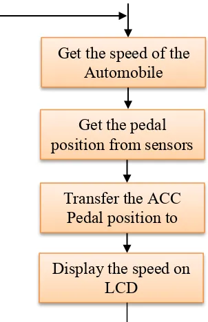
Furthermore, microcontroller is used to interface with pedal position sensor, vehicle speed sensor, ECU and the wireless module. It processes the frame and imposes the speed limit on automobile. In their process, when the accelerator pedal is moved to increment the speed, microcontroller calculated the speed that would be reached on the new pedal position if speed higher than a speed limit, then it denies excess speed and give appropriate signal to ECU as shown on Figure 2.1. kameswari, et al., December 2011.
Figure 2.1(a): Flowchart scheme of operation in Normal Mode (kameswari, et al., December 2011).
Get the speed of the Automobile
Get the pedal position from sensors
Display the speed on LCD
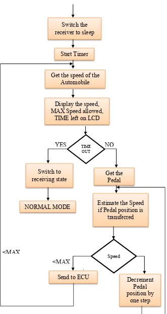
[image:18.595.242.393.412.646.2]6 Figure 2.1(b): Flowchart Schematics Operation in Active Mode (kameswari, et al.,
December 2011). Switch the
receiver to sleep
Start Timer
Get the speed of the Automobile
Display the speed, MAX Speed allowed,
TIME left on LCD
Switch to
receiving state Get the Pedal
NORMAL MODE Estimate the Speed if Pedal position is transferred
Send to ECU Decrement
Pedal position by
one step
TIME OUT
Speed
YES NO
<MAX
[image:19.595.141.472.67.689.2]7 Furthermore, according to Thomas, et al., May 2014, DC Motor is used a Pulse Width Modulation (PWM) technique which it’s normal to control by an accelerating units. PWM is actually width of the output pulse that is varied by varying a DC voltage reference which is given as one of the inputs to comparator. They also said that microcontroller is a low power device that can produce 5V of output where it need to isolated using Opto-Coupler (TLP250) which is used low power signal as an input and it produces corresponding high power signal as an output. They applied two methods for speed control DC motor which is closed loop and open loop.
According to B.V.V.Satayanarayan & Kona, 2014, LPC 2148 microcontroller is based on ARM7TDMI-S CPU which the ARM 7 has a characteristics which is it have 2 port for interfacing with various devices, 40kB of RAM, 512 kB of flash memory and high speed performance at speed of 60MHz. also for their researches they used two of a warning module and two of the speed control module such as Liquid Crystal Display (LCD) Module and a Buzzer and also DC Motor and Relay Module.
Next, the research done by Rao, et al., March 2014, said that they research used to stop the vehicle by using Ultrasonic sensor detect obstacle. They also use a microcontroller of AT89552 which is to check the data with the program embedded in the motor driver and perform appropriated actions on the electric DC motor. The program for their project is programmed in the embedded C language.
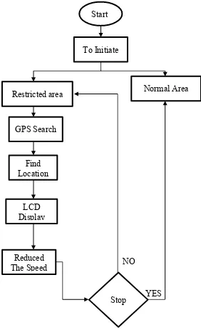
8 Figure 2.2: Flowchart of Process (Govindaraju, et al., August 2014).
As shows in Figure 2.2 above, first step is it initialize power is supplied to vehicle section and GPS as well as GSM. Then, next step is two stages are vehicle section and pedestrian limit. After that is the two areas are normal speed and restricted area. Then, the GPS ready to track the location and display the message by using LCD. Then it wills automatically getting reduced the speed by limit in step 6. After the process is completed, it getting move to original state then last step is stopping the process.
Start
To Initiate
Normal Area Restricted area
GPS Search
Find Location
LCD Display
Reduced The Speed
9 Lastly, according to Babu & Sudhakar, November 2014 they used IR LED and Photodiode in their research which is it proximity sensor when IR signal transmitted from LED depending upon the distance of the obstacle or humps there is reflection of IR beam from that, material the circuit provide the signal to microcontroller and with same process of fuel reduction technique, the vehicle fuel has been reduce and the speed of vehicle also been reduced. IR LED and Photodiode are generated a Buzzer sound to alert the vehicle. Their research also used solar panel to generate an electrical energy from natural resources like solar light. There are some application and advantages of their system which is:
i. Speed control through RF technique. ii. Speed control at humps.
iii. Speed controls when any obstacle found. iv. U curves safety indications.
v. Low power transmitter is enough for operation. vi. Lot of accidents possible is avoided.
vii. Suitable for all kinds of vehicle safety system. viii. Less man power is required
ix. Steep edges are detected. x. Driver alertness will be more.
xi. High, low beams of headlights are controlled automatically. xii. Controlling the horn of the vehicles across schools, hospitals etc. xiii. Because of using solar it will be cost effective
2.2 Hardware Overview of System
10 2.2.1 Microcontroller
[image:23.595.174.462.370.544.2]In these researches, microcontroller will be used as a platform for system can be functioning. Microcontroller is a small computer on a single integrated circuit containing a processor core, memory and programmable input/output peripherals (Dizvi, 2012). Furthermore, microcontroller also effectively has revolutionized of the standard in electronic component today which is they invent a robot to form a large consumer goods. Block diagram of the circuit and operating mode are shown in Figure 2.3 below, the 12V DC supply has been regulated to 5V using a voltage regulator. The diode 1N4001 is provide which is to reverse the protection of the connection and the capacitor is to stabilize the 5 V supply. However, the voltage regulators is generally do not functioning in correctly unless the circuit input supply is approximately 8V or higher (Nicolae & Marcel, May 2014).
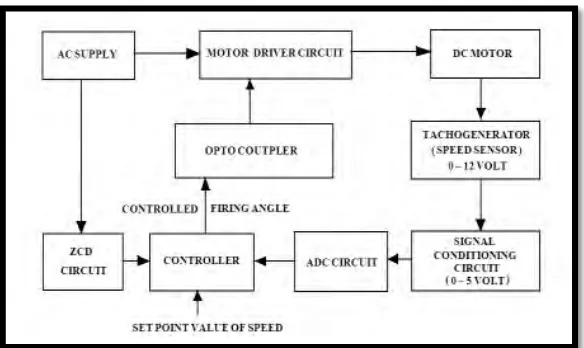
11 Figure 2.4: Block Diagram of Closed Loop DC Motor Speed Control System
(Mondal, et al., 2013).
In the proposed design shown in Figure 2.4. a DC motor of 12 Volt, 1000 rpm, Zero Crossing Detector (ZCD) for zero reference and a Tachogenerator as a Speed sensor has been used. This system describes that the design and implementation of the AT89c51 Microcontroller based closed loop DC Motor Speed Control System that controls the speed of a DC motor through Optically Coupled Half Controlled SCR bridge rectifier used as a Motor Driver circuit. In the research, they used to design and develop AT89c51 Microcontroller based embedded closed loop speed control system of DC Motor where Proportional (P) Control algorithm has been implemented to control the firing angle of the SCR for controlling the voltage applied to the DC Motor. Microcontroller in the design has been fed with the tachogenerator output voltage after conversion into suitable form by the signal conditioning circuit designed (Mondal, et al., 2013)