UNIVERSITI TEKNIKAL MALAYSIA MELAKA
OPTIMIZATION PROCESS OF T-SHAPED MICROSTRIP
ANTENNA PERFORMANCE FOR BROADBAND
This report submitted in accordance with requirement of the Universiti Teknikal Malaysia Melaka (UTeM) for the Bachelor’s Degree in Electrical
Engineering Technology (Telecommunication) with Honours
by
MOHAMMAD NAZRIN BIN JOHARI B071310401
911026-08-5223
UNIVERSITI TEKNIKAL MALAYSIA MELAKA
BORANG PENGESAHAN STATUS LAPORAN PROJEK SARJANA MUDA
TAJUK:
Optimization Process of T-shaped Microstrip Antenna Performance for Broadband
SESI PENGAJIAN: 2016/2017 Semester 1
Saya MOHAMMAD NAZRIN BIN JOHARI
mengaku membenarkan Laporan PSM ini disimpan di Perpustakaan Universiti Teknikal Malaysia Melaka (UTeM) dengan syarat-syarat kegunaan seperti berikut:
1. Laporan PSM adalah hak milik Universiti Teknikal Malaysia Melaka dan penulis. 2. Perpustakaan Universiti Teknikal Malaysia Melaka dibenarkan membuat salinan
untuk tujuan pengajian sahaja dengan izin penulis.
3. Perpustakaan dibenarkan membuat salinan laporan PSM ini sebagai bahan pertukaran antara institusi pengajian tinggi.
4. **Sila tandakan ( )
SULIT
TERHAD
TIDAK TERHAD
(Mengandungi maklumat yang berdarjah keselamatan atau kepentingan Malaysia sebagaimana yang termaktub dalam AKTA RAHSIA RASMI 1972)
(Mengandungi maklumat TERHAD yang telah ditentukan oleh organisasi/badan di mana penyelidikan dijalankan)
Alamat Tetap:
No 4019 Taman Tunku Puan Chik,
72100 Bahau,
Negeri Sembilan
Tarikh: 9TH DECEMBER 2016
Disahkan oleh:
Cop Rasmi:
iv
DECLARATION
I hereby, declared this report entitled “Optimization Process of T-shaped Microstrip Antenna Performance for Broadband” is the results of my own research
except as cited in references.
Signature : ……….
Author’s Name : MOHAMMAD NAZRIN BIN JOHARI
v
APPROVAL
This report is submitted to the Faculty of Engineering Technology of UTeM as a partial fulfillment of the requirements for the degree of Bachelor of Electrical Engineering Technology (Telecommunication) with Honours. The member of the supervisory is as follow:
vi
ABSTRAK
Secara umumnya, antena adalah alat yang telah digunakan untuk menghantar dan menerima isyarat frekuensi. Tampalan jalur mikro antena adalah paling digemari untuk struktur antena dalam usaha yang minima dan konfigurasi dikurangkan untuk sistem tanpa wayar serta aplikasi RF. Hari ini, pelaksanaan antena jalur mikro yang dihasilkan dalam pelbagai kegunaan untuk kawasan telekomunikasi. Malangnya, penghasilan antena jalur mikro dalam jalur frekuensi tertentu seperti jalur lebar jarang dihasilkan. Oleh itu, projek ini bercadang untuk membangunkan antena jalur mikro yang berbentuk T khusus untuk penggunaan jalur lebar. Projek ini juga adalah memberi tumpuan kepada penghasilan dua (2) jenis antena jalur mikro yang merupakan tampalan berbentuk T. Tampalan antena jalur mikro direka menggunakan perisian Advance System Design (ADS). Dalam projek ini, antena jalur mikro telah dianalisis oleh empat (4) parameter. Parameter ini adalah Dimensi, Sudut Polarisasi, Frekuensi dan Jarak untuk mendapatkan keluaran kuasa yang terbaik sebagai tindakbalas. Dari empat parameter tersebut, sebahagian analisis telah dijalankan bagi
mengkaji kesan parameter dengan menggunakan 24 kaedah reka bentuk faktorial.
vii
ABSTRACT
Generally, antenna is a device that had been used for transmitting and receiving frequency signal. Micro strip patch antenna is a standout amongst the most favoured antenna structures for minimal effort and minimized configuration for wireless system and RF application. Present day, the implementations of micro strip antennas are produced for variety usage for telecommunication area. Unfortunately, producing micro strip antenna in a particular frequency band which for broadband is seldom developed. Hence, this project is proposing to develop a T-shaped micro strip antenna specifically for broadband usage. This project is focus on produce two (2) types of micro strip antennas which is T-shaped patch. The patch of micro strip antennas were designed using Advance System Design (ADS) Software. In this project, the micro strip antennas were be analyzed by four (4) parameters. These parameters are Dimension, Polarization Angle, Frequency and Distance to obtain the best output power as the response. From that four parameters, the analysis part was conducted on studying the effect of the parameters by using 24 factorial design method. The analysis
viii
DEDICATION
This humble effort especially dedicated to my family, lecturers and friends for their support, guidance and encouragement upon completing this projects and report.
ix
ACKNOWLEDGEMENT
In the name of Allah S.W.T, the Most Gracious who has given me the strength and ability to complete this projects. Praise to Him who seek help and guidance and under His benevolence we exist and without His help, this project could not have been accomplished.
I would like to take this opportunity to show my appreciations to my beloved supervisor, also to my co-supervisor whom in the period of doing my research, always gives me the guidance Mdm Rahaini Binti Md Said and Mr. Md Ashadi Bin Md. Johari. All the information and knowledge that they gave were priceless and have contributed to the completion of this project. Although there were so many weaknesses in myself, they never give up to help me in proceeding this project.
A special gratitude also dedicated to my family who always gave me supports, advices and help me throughout my study. I really appreciated all of the help and encouragement that were given to me along the period of doing this project. It was their kindness that gave me opportunity to successfully complete this project
x
TABLE OF CONTENT
Abstrak
Abstract
Dedication
Acknowledgement Table of Content
List of Tables
List of Figures
CHAPTER 1: INTRODUCTION
vi vii viii ix x xiii xiv 1-3
1.1Background of the Project 1
1.2 Problem Statement 2
1.3Objectives 3
1.4Scope 3
CHAPTER 2: LITERATURE REVIEW 4-14
2.1 Microstrip Antenna 4
2.2 Microstrip Patch Antenna 6
2.3 Feeding Techniques 7
2.4 Antenna Parameters 10
2.4.1 Radiation Pattern 10
2.4.2 VSWR 11
2.4.3 Gain 11
2.4.4 Return Loss 11
2.5 Design of Experiment Software 12
2.5.1 Factorial Design 13
2.6 ADS Momentum Software 13
xi
CHAPTER 3: METHODOLOGY 15-37
3.1 Identify the Problem 15
3.2 Project Planning 15
3.3 Variable Identification 17
3.3.1 Dimension 17
3.3.2 Distance 17
3.3.3 Frequency 18
3.3.4 Polarization Angle 18
3.4.1 Designing Steps
3.5 Method Selection (Hardware Process) 3.5.1 Print Steps
3.5.2 Etching Steps 3.5.3 Soldering Steps
3.6 Method Selection (Testing Process) 3.6.1 Data Collection
3.7 Method Selection (Factorial Design) 3.7.1 Clarify and State Objective
3.7.2 Choose Responses
xii
CHAPTER 4: RESULT AND DATA ANALYSIS
4.1 Experiment Result 4.2 Analysis of Result 4.3 Optimization of Result 4.4 Discussion
CHAPTER 5: CONCLUSION AND RECOMMENDATION
5.1 Conclusion 5.2 Recommendation
REFERENCES
38-52
38 40 49 51
53-54
53 54
xiii
LIST OF TABLES
2.1 Table of characteristic of micro strip patch antennas, micro strip slot antennas and printed dipole antennas.
5
2.2 Advantages and disadvantages of micro strip antenna. 6
2.3 Types of feed techniques. 8
3.1 Properties of experiment. 40
3.2
4.1
4.2
4.3
4.4
4.5
Matrix Design of Experiment.
Experimental result of output power.
ANOVA table for output power.
Optimization conditions setting.
Optimization results (the first 5 over 100 results displayed).
Optimization result with level of properties.
42
45
47
58
58
xiv
LIST OF FIGURES
Figure 2.1 Micro strip antenna configuration. 4
Figure 2.2 Different shapes of micro strip patches. 7
Figure 2.3 Stepwise simulation of ADS Momentum. 15
Figure 3.1 Flow chart of this project. 17
Figure 3.2
Flow chart of implementation T-shaped micro strip antenna by using ADS Momentum Software.
21
Figure 3.3 Geometry of the Patch Antenna. 22
Figure 3.4 Figure 3.5 Figure 3.6 Figure 3.7 Figure 3.8 Figure 3.9 Figure 3.10 Figure 3.11
Schematic diagram for T-shaped of patch antenna.
Layout window ADS showing the T-shaped of patch antenna.
The T-shaped patch of micro strip antenna on sticker paper.
The patch of micro strip antenna was attached onto PCB board.
The patch of micro strip antenna completed attach.
The UV Process.
PCB developer process
The patch of antenna after PCB developer process.
xv Figure 3.12 Figure 3.13 Figure 3.14 Figure 3.15 Figure 3.16 Figure 3.17 Figure 3.18 Figure 3.19 Figure 3.20 Figure 3.21 Figure 3.22 Figure 3.23 Figure 3.24 Figure 4.1
The Etching Process.
The patch of micro strip antenna after Etching process.
The Etching Cleaning process.
The patch of micro strip antenna after Etching Cleaning process.
The T-shaped microstrip antenna.
Soldering process.
The T-shaped microstrip antenna with SMA connector.
The data collection for T-shaped microstrip antenna.
a) The microstrip antenna at dimension 5.0 cm. b) The microstrip antenna at dimension 2.5 cm.
a) Polarization angle at 90˚. b) Polarization angle at 180˚.
a) Frequency at 2.1 GHz. b) Frequency at 2.7 GHz.
a) Distance at 15 cm. b) Distance at 30 cm.
Flow chart of experiment by using Factorial Design.
Normal plot for output power.
xvi Figure 4.2
Figure 4.3
Figure 4.4
Figure 4.5
Figure 4.6
Figure 4.7
Figure 4.8
Figure 4.9
Pareto chart for output power.
Normal plot of residuals graph for output power.
Residual versus predicted graph for output power.
One factor effect plot for A (dimension).
One factor effect plot for B (polarization angle).
One factor effect plot for D (distance).
Interaction effect plot for AC (dimension and frequency).
Interaction effect plot for CD (frequency and distance)
50
51
52
53
54
55
56
xvii
LIST OF ABBREVIATIONS, SYMBOLS AND
NOMENCLATURE
ADS - Advance Design System ANOVA - Analysis of Variance DOE - Design of Expert
D - Directivity
dB - Decibel
F - F Test (ANOVA)
G - Gain
˚ - Degree
ƞ - Eta (Efficiency)
Г - Gamma (Gain)
> - More than
φ - Phi (Gain)
1
1.1 BACKGROUND
Antenna is a device had been used in the process of sending or receiving signals in the form of wave frequency. Usually, this antenna system is commonly in radio frequency or RF and process delivery and receipt of signals will involve two or more stations to ensure that desire signal (frequency) reach at the address of the site. For example, a song from the radio stations can be heard by the listener. This is because the song was transmitted from radio station via satellite and satellite will transmitted the song to the listener. Hence, the song from the radio station has become the transmitter antenna to the receiver (satellite). Meanwhile, the satellite will become transmitter antenna and the signal will be transmit directly to the listener.
Microstrip antenna was initially presented in the 1950s. However, this idea needed to wait for around 20 years to be acknowledged after the advancement of the printed circuit board (PCB) technology in the 1970s. From that point, microstrip antennas are the most common sorts of antennas with extensive variety of utilizations because of their apparent advantages of light weight, low profile, low cost, planar configuration, simple of conformal, predominant convey ability, reasonable for array with the ease of fabrication and integration with microwave monolithic integrate circuits (MMICs).
2 Therefore, the focus of this project is to produce a T-shaped micro strip antenna for broadband usage. In this project, Design of Experiment (DOE) Software will be used to evaluate the performance of T-shaped micro strip antenna. As a result, the best combination of properties for the T-shaped micro strip antenna that reach maximum and optimum results in transmitting and receiving signal for broadband usage are achieved.
1.2 PROBLEM STATEMENT
Generally, antenna is a device that had been used for transmitting and receiving frequency signal. Micro strip patch antenna is a standout amongst the most favoured antenna structures for minimal effort and minimized configuration for wireless system and RF application.
3
1.3 OBJECTIVES
In this research, the main objectives of this project are:
i. To study and develop T-shaped micro strip antenna by using Advance Design System (ADS) Software for broadband applications.
ii. To identify a significant effect of T-shape micro strip antenna properties for broadband applications.
iii. To determine the optimal T-shaped micro strip antenna properties for improvement of T-shaped micro strip antenna performance.
1.4 SCOPES
The scope of this research will be focus primarily on the optimization of T-shaped micro strip antenna performance for broadband applications. This antenna will print on the negative strip board and the T-shaped antenna will be design by using ADS Momentum. There are four properties will be emphasized during this research was conducted which are distance, frequency, polarization angle and dimension. Each of those properties has two different level values. All data collection will be analyses by using Factorial Design. .
4
2.1 MICRO STRIP ANTENNA
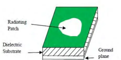
[image:20.595.242.473.480.596.2]Antenna is a transducer which transmits or receives electromagnetic waves. Micro strip antennas have a few points of interest over traditional microwave antenna and in this way are utilized as a part of practical applications. Micro strip antenna in its easiest configuration is appeared in Figure 2.1. It comprises of a transmitting patch on one side of dielectric substrate (Єr≤10), with a ground plane on other side [1].
Figure 2.1: Micro strip antenna configuration.
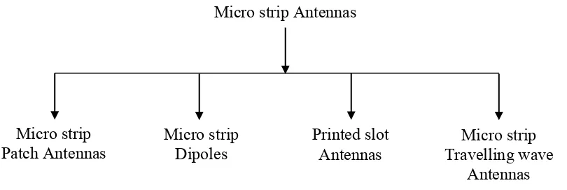
Microstrip antennas are characterized by a larger number of physical parameters than are conventional microwave antennas. They can be intended to have numerous geometrical shapes and dimensions [2]. All microstrip antennas can be partitioned into four fundamental categories
5 The characteristic of micro strip patch antennas, micro strip slot antennas and printed dipole antennas are compared in table 2.1 [3].
Table 2.1: Table of characteristic of micro strip patch antennas, micro strip slot antennas and printed dipole antennas.
Characteristics Micro strip Patch Antenna
Micro strip Antenna
Printed Dipole Antenna
Profile Slim Slim Slim
Fabrication Very simple Simple Simple
Polarization Linear and circular
Linear and circular
Linear
Shape flexibility Any shape Mostly
rectangular and circular shapes
Rectangular and triangular
Spurious radiation Exists Exists Exists
Bandwidth 2-50% 5-30% -30%
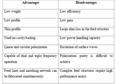
Micro strip antenna has a few preferences over conventional microwave antenna with one comparability of frequency range from 100 MHz to 100 GHz same in both sort. The various advantage and disadvantage are given in table 2.2 [4].
Micro strip Antennas
Micro strip
Dipoles Printed slot Antennas Travelling wave Micro strip Antennas Micro strip
6 Table 2.2: Advantages and disadvantages of micro strip antenna.
Advantages Disadvantages
Low weight Low efficiency
Low profile Low gain
Thin profile Large ohm loss in the feed structure Need no cavity backup Low power handling capacity Linear and circular polarization Excitation of surface waves Capable of dual and triple frequency
operation
Polarization purity is difficult to achieve
Feed lines and matching network can be fabricated simultaneously
Complex feed structures require high performance arrays.
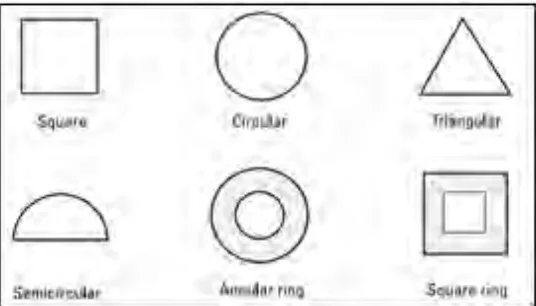
2.2 MICRO STRIP PATCH ANTENNA
A micro strip patch antenna (MPA) comprises of a conducting patch of any planar or non-planar geometry on one side of a dielectric substrate with a ground plane on other side.
7 Figure 2.2: Different shapes of micro strip patches.
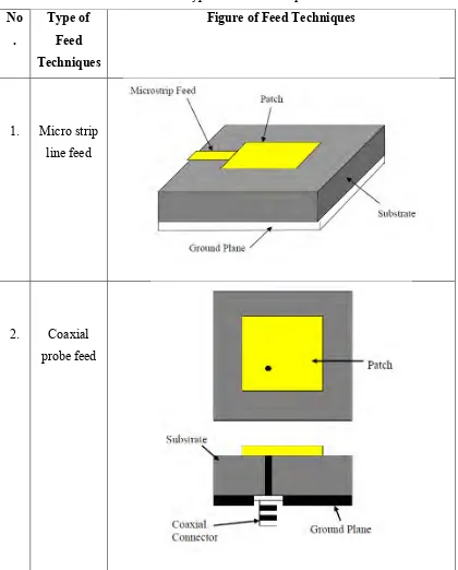
2.3 FEEDING TECHNIQUES
8 Table 2.3: Types of feed techniques.
No .
Type of Feed Techniques
Figure of Feed Techniques
1. Micro strip line feed