THE DEVELOPMENT OF HYDROGEN CELL FOR PETROL-POWERED ENGINE
NIDZAMUDDIN MD. YUSOF
RESEARCH VOTE NO: PJP/2013/FKM(16A)/S01262
FakultiKejuruteraanMekanikal UniversitiTeknikal Malaysia Melaka
i
THE DEVELOPMENT OF HYDROGEN CELL FOR
PETROL-POWERED ENGINE
(Keywords: Hydrogen, Internal Combustion Engine, Hydrogen Cell, Emission)
ii
Key Researchers:
NidzamuddinMdYusof JuffrizalKarjanto Mastura Mohammad Taha Muhammad Zulfattah bin Zakaria
Muhammad Nur bin Othman
Email: [email protected] Tel. Number: 06-2346854
iii
ACKNOWLEDGEMENTS
Given this opportunity, I would like to express my deepest gratitude to Allah S.W.T for His guidance and blessings that give me strength and wisdom to complete this project.
I would also like to extend my special appreciation to my co-researchers, Juffrizal Karjanto, Mastura Mohammad Taha, Muhammad Zulfattah Zakaria dan Muhammad Nur bin Othman for their tremendous dedications and commitments throughout this project.
Special thanks to the top level management of Universiti Teknikal Malaysia Melaka (UTeM), including Integrated Design Research Group (IDEA) and Faculty of Mechanical Engineering administrators for the funding from the Short Term Grant (PJP) that make this research possible.
Other thanks to my Project Sarjana Muda (PSM) student, Siti Nadzirah Tupani for her continuous commitments and contributions.
iv
TABLE OF CONTENT
ACKNOWLEDGEMENTS ... iii
TABLE OF CONTENT ... iv
LIST OF FIGURES ... vii
LIST OF TABLES ... ix
LIST OF APPENDICES ...x
1 CHAPTER 1: INTRODUCTION ...1
1.1 Problem Statements ...2
1.2 Objectives ...2
2 CHAPTER 2: LITERATURE REVIEW ...3
2.1 Internal Combustion Engine (ICE) ...3
2.2 Properties of hydrogen ...4
2.3 Water Electrolysis ...4
2.3.1 Method of production of hydrogen based on electrolysis ...5
2.3.2 Alkaline electrolysis ...5
2.3.3 Proton exchange membrane (PEM) water electrolysis ...6
2.3.4 Steam electrolysis ...7
2.3.5 Hydrogen as by product from chlor-alkali production ...8
2.4 Type of hydrogen cell ...8
2.4.1 Wet cell ...8
2.4.2 Dry cell ...9
2.5 Material of electrode ... 10
2.5.1 Electric conductivity ... 10
2.5.2 Corrosion resistance ... 10
2.5.3 Price ... 10
2.6 Type of electrolyte ... 10
v
2.8 Bubbler tank ... 12
2.8.1 Material for bubble tank and reservoir ... 12
2.9 Method of hydrogen injection... 14
2.10 Emission ... 18
3 CHAPTER 3: METHODOLOGY ... 20
3.1 Introduction ... 20
3.2 Product Architecture ... 20
3.2.1 Schematic of Product Element ... 20
3.2.2 Product Cluster ... 21
3.2.3 Product Geometry... 23
3.2.4 Fundamental and Incidental Interaction ... 23
3.3 Morphological Chart ... 24
4 CHAPTER 4: RESULT AND DISCUSSION ... 27
4.1 Design ... 27
4.1.1 Stainless steel plate ... 27
4.1.2 Acrylic end plate ... 28
4.1.3 Gasket ... 29
4.1.4 Bolt and Nut ... 30
4.1.5 Assembly of the cell ... 30
4.1.6 Tank ... 31
4.2 Prototyping ... 32
4.2.1 Stainless steel plate ... 32
4.2.2 Acrylic end plate ... 36
4.2.3 Gasket ... 37
4.2.4 Assembly process ... 38
4.2.5 Tank ... 39
vi
4.4 Problems ... 41
5 CHAPTER 5: CONCLUSION AND FURTHER WORKS ... 43
5.1 Conclusion ... 43
5.2 Further Works ... 43
6 REFERENCES ... xi
vii
LIST OF FIGURES
Figure 1: Injection of hydrogen into the internal combustion engine ...3
Figure 2: Electrolysis process ...6
Figure 3: Proton exchange membrane (PEM) electrolysis ...7
Figure 4: Application of wet cell ...9
Figure 5: Parts in dry cell ...9
Figure 6: Bubbler tank ... 12
Figure 7: Reservoir tank ... 13
Figure 8: Hydrogen injector ... 14
Figure 9: Carburetion Injection ... 15
Figure 10: Time manifold injection ... 16
Figure 11: Continuous manifold injection ... 16
Figure 12: Direct cylinder injection ... 17
Figure 13: The schematic of product element. ... 20
Figure 14: Product Cluster ... 21
Figure 15: Product Geometry ... 23
Figure 16: Fundamental and Incidental Interaction. ... 23
Figure 17: Voltage distribution for each plate... 27
Figure 18: The drawing of the neutral plate in Catia ... 28
Figure 19: The drawing of charge plate in Catia ... 28
Figure 20: The design of a first acrylic end plate in Catia. ... 29
Figure 21: The design of a second acrylic endplate in Catia. ... 29
Figure 22: The design of gasket in Catia ... 30
Figure 23: The type of bolt and nut used ... 30
Figure 24: The entire component needs for a cell ... 31
Figure 25: The complete design of the HHO cell ... 31
Figure 26: The design of the tank in Catia ... 32
Figure 27: Shearing machine ... 33
Figure 28: Sample of the stainless steel plates after being cut with the shearing machine. ... 33
Figure 29: Bench drill ... 34
Figure 30: The size of drill bits used in sequence. ... 34
viii
Figure 32: The stainless steel plate condition after being scored. ... 35
Figure 33: Acrylic plate is being cut off by using the hand jigsaw ... 36
Figure 34: 20mm diameter size of drill bits. ... 36
Figure 35: The cloth that covered the gasket layer need to be peel out first. ... 37
Figure 36: Holes is done with the help of puncher ... 37
Figure 37: The plates is arranged one by one according to the order ... 38
Figure 38: The assembled HHO cell... 38
Figure 39: PVC end cap with diameter of 50 mm ... 39
Figure 40: The saw used to cut out the PVC pipe ... 39
Figure 41: The PVC solvent used to joint both of the PVC pipe and the end cap. .... 39
Figure 42: The tank that has been fabricated and assembled. ... 40
Figure 43: The arrangement of the HHO cell ... 40
Figure 44: Passivation process by using lime water and the aquarium pump... 41
ix
LIST OF TABLES
Table 1: Properties of hydrogen ...4
Table 2: Comparison between the classification, hydrogen flow timing and the supply pressure for four different mixture formations. ... 18
Table 3: Hydrogen fuel cell ... 24
Table 4: Bubbler tank... 25
Table 5: Reservoir ... 25
Table 6: Cover ... 26
x
LIST OF APPENDICES
Appendix A: Drawing and dimension of first acrylic end plate ... xv
Appendix B: Drawing and dimension of second acrylic end plate ...xvi
Appendix C: Drawing and dimension of charge plate ... xvii
Appendix D: Drawing and dimension of neutral plate ... xviii
1
CHAPTER 1: INTRODUCTION
Fossil fuels are the primary coal, natural gas or petroleum that comes from the dead animals and plant which remains under the soil. These dead animal and plant remains under the soil and getting covered by the sediment time over time. Thus, the reaction of the pressure and the heat cause the dead animal and plant turn into the fossil fuels which need to be mined. Fossil fuel also can be said as hydrocarbon substance that used as an energy source. Fossil fuels are important energy resources, it can be used as a vehicle fuel, powering the electric plant and even being used in our daily routine such as toothpaste, cosmetic, medicine, plastic product and the synthetic fabrics (Woodrow W. Clark, 2004).However, due to the high requirement of this fossil fuel, the sources of the fossil fuel begin to deplete as it is a non-renewable. This problem will seriously affect the automotive industry which totally depends on the fossil fuel because the depletion of fossil fuel will lead to the economic rise due to increment of fossil fuel price.
In order to find the solution of this problem, researcher had working very hard to find the replacement or ways to reduce the usage of the fossil fuel. Thus, after considering a lot of aspect of the fuel, the best alternative to reduce the usage of the fossil fuel in internal combustion engine is by using the hydrogen. Hydrogen is expected to be the best option in the state of gas compared to in liquid state by referring to the rate of emission (Ahmed, 2012). The usage of hydrogen for the internal combustion engine can reduce the rate of emission by reducing the production of carbon monoxide, nitrogen oxide, hydrocarbon and other harmfulparticle (Sa'ed A Musmar, 2011).
2
Problem Statements
The rate of pollution nowadays had become worse. One of the main causes of the air pollution is the burning of the fossil fuel from the vehicle. This is because the exhaust from the vehicle contains harmful gases such as carbon monoxide, nitrogen oxide, hydrocarbon and many other harmful particles. The increment of the air pollution index need to be worried as it can cause acidification, eutrophication andgreenhouse effect.
Acidification is the formation of acid rain when the harmful gases were combining with the water particle in the air. This acid rain can cause harm not just to the living creature such as plant and wildlife, it also can cause the building to face corrosion. Meanwhile, eutrophication is the effect towards the soil and water by the acid rain which makes the soil and water to become acidic. The exhaust gas from the vehicle can also cause the ozone layer to become thinner and this lead to the climate change and this is called the greenhouse effect.
As a non-renewable source, the production of the fossil fuel is being depleted and cannot be recovered. This problem will get worse in a meantime. The one that will affect most of this issue must be the automotive industry which is still depends on the fossil fuel production. It will also affect the user of the vehicle in person because depletion of the fossil fuel production will cause an increment of the cost of running the vehicle. Thus, the solutions for this problem need to be found out as soon as possible in order to overcome the incoming problem.
Objectives
The objectives of this project are as listed below:
1. To study the effect of hydrogen hybrid to the performance of internal combustion engine.
CHAPTER 2:
Internal Combustion Engine (ICE)
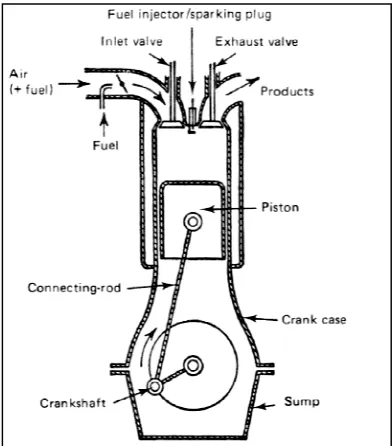
There is four phase in the four stroke engine which is induction, compression, power and exhaust. At the induction phase, the intake valve will open and
will move down at the same time to pull down the air and fuel or the air only. After that, both of the intake and exhaust valve will be closed while the piston will move upward and cause the air or the air mixture being compress. This is called compression phase.
[image:14.612.228.424.430.653.2]After the compression phase, there will be the power stroke phase. At this phase, the fuel will starting to burn thus will increase the temperature and the pressure. This high temperature and pressure will force the piston to move downward. At this state, the crankshaft is starting to rotate. The rotation will cause the piston to move upward and forcing the exhaust to move out through the open exhaust valve. The exhaust valve will be close again and the cycles being repeat again and again (Wall, 2008)
Figure 1: Injection of hydrogen into
CHAPTER 2: LITERATURE REVIEW
Internal Combustion Engine (ICE)
There is four phase in the four stroke engine which is induction, compression, power and exhaust. At the induction phase, the intake valve will open and
will move down at the same time to pull down the air and fuel or the air only. After that, both of the intake and exhaust valve will be closed while the piston will move upward and cause the air or the air mixture being compress. This is called
After the compression phase, there will be the power stroke phase. At this phase, the fuel will starting to burn thus will increase the temperature and the pressure. This high temperature and pressure will force the piston to move ownward. At this state, the crankshaft is starting to rotate. The rotation will cause the piston to move upward and forcing the exhaust to move out through the open exhaust valve. The exhaust valve will be close again and the cycles being repeat
(Wall, 2008).
: Injection of hydrogen into the internal combustion engine (Jacob Wall, 2008)
3 There is four phase in the four stroke engine which is induction, compression, power and exhaust. At the induction phase, the intake valve will open and the piston will move down at the same time to pull down the air and fuel or the air only. After that, both of the intake and exhaust valve will be closed while the piston will move upward and cause the air or the air mixture being compress. This is called the
After the compression phase, there will be the power stroke phase. At this phase, the fuel will starting to burn thus will increase the temperature and the pressure. This high temperature and pressure will force the piston to move ownward. At this state, the crankshaft is starting to rotate. The rotation will cause the piston to move upward and forcing the exhaust to move out through the open exhaust valve. The exhaust valve will be close again and the cycles being repeat
4
Properties of hydrogen
There are several type of alternative fuel which is biomass, biogas, primary alcohol, vegetable oil and hydrogen. However, hydrogen became the main attraction due to its simple reaction between the oxygen and water which is known as a clean method. It is also known as the only alternative fuel that can be produce from the water which is renewable source (Kahraman, 2005).
Other than that, hydrogen also have a wider flammability limit, high energy density, significant structure for the non-content of the carbon atoms and the high velocities of burning (Premkartikkumar SR, 2012). It is proved that the mixing between hydrogen and the natural gas will reduce the emission level and increase the combustion efficiency.
[image:15.612.165.481.446.601.2]This is referring to the shorter period for propagation and flame development in the internal combustion engine when hydrogen is being used (Kasianantham Nanthagopal, 2011). The properties of the hydrogen are shown in the table below:
Table 1: Properties of hydrogen (Premkartikkumar SR, 2012)
Limits of flammability in air 4 – 75% vol.
Minimum energy for ignition 0.02mJ
Auto ignition temperature 858 K
Guenching gap in NTP air 265-325 cm/s
Diffusion coefficient in NTP air 0.61 cm2/s
Heat of combustion (LCV) 119.93 MJ/kg
Water Electrolysis
5 during 1939(Cameron, 2012). However, at year 1977, Yull Brown had stepped out to patent the technique used to generate oxyhydrogen (HHO) gas which is electrolysis process (Sa'ed A Musmar, 2011). This HHO gas also known as a Brown gas which is referring to the name of Yull Brown himself.
Basically, the electrolysis process is a process where the water (H2O) is split into hydrogen and oxygen gas. This process can be done when the two electrodes with positive and negative charge is connected with the electrical power supply. Both of these electrodes is placed in an electrochemical cell which filled with the pure water. The voltage supply to the both of electrode will then cause the electrode to react and produce oxygen at the positive electrode and hydrogen at the negative electrode (Varkaraki, 2004). The equation for the reaction is shown below:
Overall Reaction:2H2O →2H2+O2 (1)
2.2.1 Method of production of hydrogen based on electrolysis
There are several methods to produce hydrogen based on water electrolysis such as alkaline electrolysis, proton exchange membrane water electrolysis, steam electrolysis and hydrogen as by product from chlor-alkali production (Varkaraki, 2004).
2.2.2 Alkaline electrolysis
Despite using the acidic electrolysis, alkaline electrolysis is a more preferred method. This is because the rate of corrosion produced can be controlled more easily compared to the acidic electrolysis. Other than that, alkaline base market price is the lowest compare to the other method (Gouws, 2012). The anode used in alkaline electrolyzer is usually made from copper or nickel covered by wolfram, ruthenium and oxides of mangan.
hydrogen will move to the anode through the electrolytic material. This is where the hydrogen will form (Olga Bicakova, 2012)
Overall Reaction: H2
Anode reaction: 4OH
Cathode reaction: 2H
2.2.3 Proton exchange membrane (PEM) water electrolysis
The proton exchange membrane (PEM) water electrolysis has a least corrosion rate compare to the alkaline electrolysis method. Other than that, compare to the alkaline electrolysis, the rate of explosion between oxygen and hydrogen is minimum in PEM water e
electrolysis is it has a higher rate of production and can come up in a more compact design.
to the anode through the electrolytic material. This is where the (Olga Bicakova, 2012):
2 2
2O →2H +1/2O
O H O
OH → 2 +2 2 −
−
− → +
+ e H OH
O
[image:17.612.201.453.281.484.2]H2 2 2 2
Figure 2: Electrolysis process (Source: Shawn Gouws, 2012)
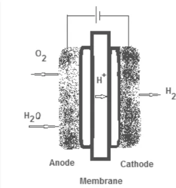
Proton exchange membrane (PEM) water electrolysis
The proton exchange membrane (PEM) water electrolysis has a least corrosion rate compare to the alkaline electrolysis method. Other than that, compare to the alkaline electrolysis, the rate of explosion between oxygen and hydrogen is minimum in PEM water electrolysis. The other advantage for the PEM water electrolysis is it has a higher rate of production and can come up in a more compact
6 to the anode through the electrolytic material. This is where the
(2)
(3)
(4)
In PEM electrolyzer, the cathode and anode are bonded together with the membrane electrode assembly (MEA). Diff
PEM electrolyzer produce hydrogen by supplying the water to the anode. It will later broke into hydrogen, oxygen ion and the electron. This hydrogen ion will then travel to the cathode through the MEA. At the catho
combine to form the hydrogen gas shown below:
Overall Reaction:
Anode reaction:
[image:18.612.250.426.362.550.2]Cathode reaction:
Figure 3: Proton exchange membrane (PEM) electrolysis
2.2.4 Steam electrolysis
Steam electrolysis is a method where the water is fed on the cathode. At the cathode also the gas which is usually a mixture between the hydrogen and steam is supplied. Through this process, the voltage that higher than the open circuit voltage In PEM electrolyzer, the cathode and anode are bonded together with the membrane electrode assembly (MEA). Different with the alkaline electrolysis, the PEM electrolyzer produce hydrogen by supplying the water to the anode. It will later broke into hydrogen, oxygen ion and the electron. This hydrogen ion will then travel to the cathode through the MEA. At the cathode, the electron and the proton will combine to form the hydrogen gas (Gouws, 2012). The equation of reaction is as
Overall Reaction: 2H2O →2H2+O2
Anode reaction: H2O→4H+ +O2 +4e−
Cathode reaction: 2H2O+4e− →2H2
: Proton exchange membrane (PEM) electrolysis (Source: Shawn Gouws, 2012)
Steam electrolysis is a method where the water is fed on the cathode. At the cathode also the gas which is usually a mixture between the hydrogen and steam is supplied. Through this process, the voltage that higher than the open circuit voltage
7 In PEM electrolyzer, the cathode and anode are bonded together with the erent with the alkaline electrolysis, the PEM electrolyzer produce hydrogen by supplying the water to the anode. It will later broke into hydrogen, oxygen ion and the electron. This hydrogen ion will then travel de, the electron and the proton will . The equation of reaction is as
(5)
(6)
(7)
8 need to be applied so that the oxygen can be pump out from the steam to the air(Bilge Yildiz, 2005).
However, this will lead a waste to the 60% to 70% of the electrical power to force the electrolyzer work against the chemical potential gradient for oxygen which is high. Other than that, the production of oxygen cause by the decomposition of water to the air also consider as a waste.
To overcome the problem regarding the electric consume in the steam electrolysis method, the natural is used so that the chemical potential difference between the electrolyzer cells can be reduced. This method can be done by replacing the air at the anode with the natural gas. This can be a big help in order to reduce the chemical potential difference between the electrolyzer(Varkaraki, 2004).
2.2.5 Hydrogen as by product from chlor-alkali production
For this method, the chlorine gas will be form through the oxidise process of the chlorine ions at the anode side. Though that there is three type of method for producing the chlorine which is membrane cell, mercury and the diaphragm .Usually, the anode side will be fed with the brine solution. While at the cathode, the water will be fed and being transfer into the hydroxyl ion and the gaseous oxygen. The sodium ion will later move from the anode to the cathode through the cation selective membrane. Sodium will then combine with the hydroxyl ion which will then leave the membrane as a sodium hydroxide (Rosanna Santorelli, 2009).
Type of hydrogen cell
2.3.1 Wet cell
9 disadvantages stated, the wet cell also has it advantage which is the wet cell did not have to completely replaced if there is any part that broken and need to be replaced (Arulampalam Kunaraj, 2012).
Figure 4: Application of wet cell (Source: Myles Moore, 2010)
2.3.2 Dry cell
Dry hydrogen cell is different with the wet cell as the electrode is not submerged into the water. The electrode is arranged in between the two end plate and the gaskets in order to fill it with the electrolyte solution and prevent leaking. The electric current and the solution is channel into the cell through the hole at the edge of the electrode plate. These avoid any electric current leakage and cause reduction at the rate of corrosion. Hence, it is more practical compare to the wet cell (Myles Moore, 2010).
[image:20.612.219.437.531.683.2]10
Material of electrode
The selection of the material for electrode is important in order to obtain optimum result fur the hydrogen production. Material for electrode must be analyzed based on several factor such as electric conductivity, corrosion resistance and its price (Ngin Mang, 2013). Below are the analysis done towards stainless steel, copper and platinum.
2.4.1 Electric conductivity
Electrical conductivity is determined based on the ability of the material to conduct electric. All of the stainless steel, copper and platinum are a good conductor. However, stainless steel is the best electric conductor compare to the other.
2.4.2 Corrosion resistance
The water electrolysis process is very corrosive to the material of the electrode. Thus, the electrode with high corrosion resistance must be selected in order to maintain the condition of the electrode so that it does not need to be replaced regularly. Stainless steel and platinum is the best option due to its high corrosion resistance. However, copper comes as a bad corrosion resistance material (Mak, 2008).
2.4.3 Price
Even though platinum are good electric conductivity and a good corrosion resistance, it comes in a high price compare to the other two metals. Thus make it unpractical to be used as an electrode that need more plate and large surface area in order to produce more hydrogen. Copper and stainless steel price shall be selected as it price is affordable.
Type of electrolyte
11 itself, hence the catalyst or electrolyte is needed to be mixed with the distilled water to conduct electricity for the electrolysis process (Kaveh Mazloomi, 2012). There are several types of electrolyte that come from salt and base to be considered as an electrolyte such as potassium hydroxide, sodium chloride, sulphuric acid and sodium hydroxide (Ming-Yuan Lin, 2011).
However, based on research there are two types of electrode that had a higher ability to remain the same during the reaction. Those are potassium hydroxide (KOH) and sodium hydroxide (NaOH). Both of the electrolytes tend to produce a more homogenous mixture of HHO gas when mixing with the distilled water. Comparing both of the electrolytes, KOH does not consumed and more stable during the reaction compare to NaOH. Thus, there is no need to add KOH each time you need to add the distilled water inside the reservoir as the KOH solution can be used again as the water inside the bubbler tank consist of KOH solution that carried into the bubbler tank. Hence, KOH will be the best choice for the electrolyte in electrolysis process (Hamelers, 2006).
Passivation process
The stainless steel plates gain their properties of corrosion resistance from the thin layer of the chromium oxides that forms on the surface of the plates. However, several mechanical processes might affect the chromium layer such as welding, cutting and grinding.(Banes).
All of this process will disturb the existing chromium surface which resulting the surface to have a lower chrome to iron ratio that keep the stainless properties of the stainless steel. Other than that, there is also a possibility that there is any contamination that deposited on the surface of the stainless steel plates during the fabrication process. (Crookes, 2004).
help of nitric or citric acidwhich can enhance the chromium oxide protective nature. (Maller, 1998).
Bubbler tank
Channelling the hydrogen
backfire problem through the cylinder. The backfire phenomenon happen when the there is an early combustion that happen inside the intake manifold of the internal combustion engine. Other than that, there is also a possibility for the electrolyte being sucked into the intak
the bubbler tank may block the electrolyte from entering the cylinder. The bubbler tank must be a closed container that filled with water connected
the intake manifolds (Ngin Mang, 2013)
2.7.1 Material for bubble tank and reservoir Bubble tank and the reservoir carefully. It is because in order t
bubble tank and the reservoir must have the optimum abilities to store the hydrogen and strong enough to prevent the tank and reservoir from exploding. Through several researches, there are three common
the reservoir. They are steel, polyethylene and the metal hydride.
help of nitric or citric acidwhich can enhance the chromium oxide protective nature.
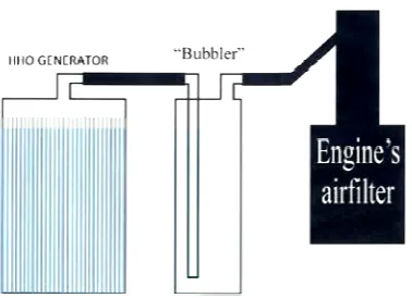
Channelling the hydrogen gas directly into the cylinder may result in severe backfire problem through the cylinder. The backfire phenomenon happen when the there is an early combustion that happen inside the intake manifold of the internal e. Other than that, there is also a possibility for the electrolyte being sucked into the intake manifold together with the hydrogen gas. Thus installing the bubbler tank may block the electrolyte from entering the cylinder. The bubbler ed container that filled with water connected to the reservoir and
[image:23.612.234.423.351.488.2](Ngin Mang, 2013).
Figure 6: Bubbler tank (Source: NginMang (2013))
Material for bubble tank and reservoir
Bubble tank and the reservoir are another critical part that must be evaluated carefully. It is because in order to create the best system for hydrogen
bubble tank and the reservoir must have the optimum abilities to store the hydrogen ng enough to prevent the tank and reservoir from exploding. Through several three common types of material that use as the bubble tank and the reservoir. They are steel, polyethylene and the metal hydride.
12 help of nitric or citric acidwhich can enhance the chromium oxide protective nature.
gas directly into the cylinder may result in severe backfire problem through the cylinder. The backfire phenomenon happen when the there is an early combustion that happen inside the intake manifold of the internal e. Other than that, there is also a possibility for the electrolyte gas. Thus installing the bubbler tank may block the electrolyte from entering the cylinder. The bubbler the reservoir and
13 Tank that made from the steel might have advantages in term of its strength. Hence it is able to withstand any impacts that come to the tank. However, this steel tank may only be suitable for the static application but not suitable to apply fora motorcycle. This is because, the steel tank is too heavy for the motorcycle and this will affect the energy efficiency of the motorcycle.
For metal hydride, the hydrogen will be able to be stored and release when needed. This is because the metal hydride can absorb the hydrogen during the low temperature and can be released by heating the metal hydride tank. This is another effective way to store hydrogen as the metal hydride tank can be heated up by the heat that wasted by the hydrogen cell(Hai - Wen Li, 2010). However, this material might be only efficient if it stored the hydrogen only but not with HHO gas. Other than that, it also comes up as an expensive and heavy material which makes it not the first choice for the bubbler tank and reservoir (L. Grinberga, 2008).
[image:24.612.228.430.489.626.2]Polyethylene as a composite material is another option as the bubble tank and reservoir material. The polyethylene is light in weight and can be easily being shaped based on the required design thus become more effective to be installed on the motorcycle. Able to resist corrosion and cheap in price is also one of the advantages of this polyethylene type of reservoir and tank (Bunsell, 2006).