INTELLIGENT VEHICLE NAVIGATION
‘IZZAT HAIMAN BIN ANUAR
This report is submitted in partial fulfillment of the requirement for the award of Bachelor of Electronic (Industrial Electronics) With Honours
Faculty of Electronic and Computer Engineering
Universiti Teknikal Malaysia Melaka
UNIVERSTI TEKNIKAL MALAYSIA MELAKA
FAKULTI KEJURUTERAAN ELEKTRONIK DAN KEJURUTERAAN KOMPUTER
BORANG PENGESAHAN STATUS LAPORAN PROJEK SARJANA MUDA II
Tajuk Projek : ……… Sesi
Pengajian : ………
Saya ……….. (HURUF BESAR)
mengaku membenarkan Laporan Projek Sarjana Muda ini disimpan di Perpustakaan dengan syarat-syarat kegunaan seperti berikut:
1. Laporan adalah hakmilik Universiti Teknikal Malaysia Melaka.
2. Perpustakaan dibenarkan membuat salinan untuk tujuan pengajian sahaja.
3. Perpustakaan dibenarkan membuat salinan laporan ini sebagai bahan pertukaran antara institusi
pengajian tinggi.
4. Sila tandakan ( √ ) :
SULIT*
(Mengandungi maklumat yang berdarjah keselamatan atau kepentingan Malaysia seperti yang termaktub di dalam AKTA RAHSIA RASMI 1972)
TERHAD* (Mengandungi maklumat terhad yang telah ditentukan oleh
organisasi/badan di mana penyelidikan dijalankan)
TIDAK TERHAD
Disahkan oleh:
__________________________ ___________________________________
(TANDATANGAN PENULIS) (COP DAN TANDATANGAN PENYELIA)
Alamat Tetap: ………...
………...
“I hereby declare that this report is the result of my own work except for quotes as cited in the references.”
Signature : ……….………..
Author : ………
“I hereby declare that I have read this report and in my opinion this report is sufficient in terms of the scope and quality for the award of Bachelor of Electronic Engineering
(Industrial Electronic) With Honours.”
Signature : ……….
Supervisor’s Name : ……….
ACKNOWLEDGEMENT
ABSTRAK
ABSTRACT
CONTENTS
CHAPTER TITLE PAGES
ABSTRAK vii
ABSTRACT viii
CONTENTS ix
LIST OF TABLES xii
LIST OF FIGURES xiii
LIST OF NOMENCLATURE xv
LIST OF APPENDICES xvi
I INTRODUCTION 1
1.1 Introduction of project 1
1.2 Operation of project 2
1.3 Objectives of project 3
1.4 Problem statements 3
1.5 Scope of work 4
1.6 Methodology of project 5
II LITERATURE REVIEW 7
2.1 Track or line guidance system 7
2.2 Obstacle avoidance system 11
2.4.1 Fuzzy driving controller (FDC) 16 2.4.2 Fuzzy braking controller (FBC) 18 2.4.3 Lateral fuzzy controller (LAFC) 19
III METHODOLOGY 21
IV RESULT AND DISCUSSION 28
4.1 Hardware 29
4.1.1 Sensor 29
4.1.1.1 Result 31
4.1.1.2 Discussion 32 4.1.2 Microcontroller 33
4.1.2.1 Result 34
4.1.2.2 Discussion 42
4.1.3 Steering 43
4.1.3.1 Result 46
4.1.3.2 Discussion 46
4.1.4 Engine 47
4.1.4.1 Result 48
4.1.4.2 Discussion 49 4.1.5 Combination Overall Circuit 49 4.1.5.1 Expected Result 51 4.1.5.2 Discussion 51
5.1 Conclusion 54
5.2 Recommendation 55
LISTS OF TABLE
NO TITLE PAGE
2.1 Set of Original and Computed Calibration Data Points 9
2.2 Rule base of FDC 17
2.3 Rule base for the FBC 19
2.4 Rule base for the LAFC 20
4.1 Experiment of infrared receiver result 31
4.2 Rule Table 34
4.3 Steering circuit result 46
4.4 Motor circuit result 48
LISTS OF FIGURE
NO TITLE PAGE
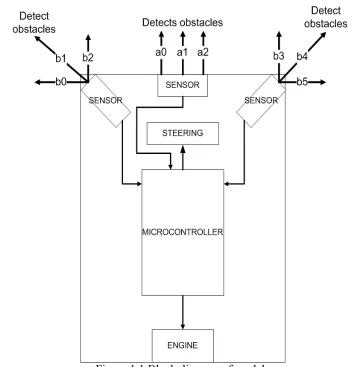
1.1 Block diagram of model 2
2.1 X and Y measuring for the measured and computed vision 8 calibration point
2.2 System block diagram 10
2.3 Obstacle avoidance strategy 12
2.4 Overall traction control system 14
2.5 Block diagram of controller 15
2.6 Membership function of fuzzy driving controller 17
2.7 Membership function of FBC 18
2.8 Membership functions of the LAFC 20
3.1 Block diagram of model 22
3.2 Atmel microcontroller 25
3.3 PIC microcontroller 25
3.4 Flow of project method 27
4.1 Receiver Circuit 29
4.2 Transmitter IR Circuit 30
4.3 Receiver IR Circuit 30
4.4 Microcontroller Circuit 33
4.5 Microcontroller circuit for rule 1 35
4.6 Microcontroller circuit for rule 2 36
4.9 Microcontroller circuit for rule 5 39
4.10 Microcontroller circuit for rule 6 40
4.11 Microcontroller circuit for rule 7 41
4.12 Steering Circuit 43
4.13 H bridge circuit in L298 44
4.14 Steering circuit 45
4.15 Engine circuit 47
4.16 Engine circuit 48
LISTS OF NOMENCLATURE
CCD - Charge-Coupled Device
MOSFET - Metal Oxide Semiconductor Field Effect Transistor IGBT - Insulated Gate Bi-polar Transistors
SCR - Silicon Controlled Rectifier PWM - Pulse Width Modulation FDC - Fuzzy driving controller FBC - Fuzzy braking controller AGV - Autonomous Guided Vehicle LAFC - Lateral fuzzy controller
PIC - Programmable Interface Controller
DC - Direct Current
PID - Proportional Integral and Derivative
IR - Infrared
LIST OF APPENDICES
NO. TITLE PAGE
CHAPTER I
INTRODUCTION
1.1 Introduction of project
Intelligent vehicle navigation is a new intelligent technology uses to drive vehicle. It can control the steering and speed of vehicle. This device controls angle of steering based on the curve of track or obstacles. For this project the track is a wall. Besides that, it also depends on the existed of obstacles front of vehicle. It also has ability to control the speed of vehicle either to reduce or improve based on the suitable condition such as take a corner and avoid obstacles.
The intelligent vehicle navigation devices can use in night or day. Both of conditions didn’t effect to this devices because the sensor can be function in night and day but this devices also has a weakness. It can’t be used in bad weather such as raining and snow. When raining the sensors has a difficulty to determine the obstacles because the water interrupts the signal from transmitter to receiver.
distance drive, it helps the driver when they are tired or exhausted and sleepy.
The intelligent vehicle navigation used the infrared sensor as an input. Then the input it will send a signal to microcontroller to decide the output. In this project, it uses the Programmable Interface Controller (PIC) as a microcontroller. The output is steering and engine.
[image:18.612.147.499.296.663.2]1.2 Operation of project
The operation of intelligent vehicle navigation is started from the detection of sensor until the output either engine or steering. When the sensor on the left of model is detects any obstacles, so the microcontroller gives the output that steering to the right. The angle of steering is control by a controller which is depends on the distance of obstacle with sensor. The angle of steering become higher when model is closed to obstacle. Besides that, it also controls the speed of model. If the obstacle is closed with model so the speed will be reduce. To reduce the speed it needs some brake on the wheel of model. The same operation if there is obstacle at right of model.
1.3 Objectives of project
The objectives of intelligent vehicle navigation project are:
1. To develop a small model of car without a driver or remote controller
2. To design a model which is has ability to turn right or left based on obstacles 3. To build a model which is can avoid obstacles
4. To design a model has ability to move in a suitable speed based on condition of track.
1.4 Problem statements
middle and side mirror have not used when take a turn. Sometimes it is because of blind spot where there is some position of behind vehicle has not seen using the mirror. The driver should be alerted the condition of road and vehicle front of them. It is very important to avoid from crash other vehicles or obstacles. Because of that, this project is designed which has ability to avoid from any obstacles such as other vehicles.
Besides that, many accidents happened because the weakness of humans. Some people have difficulty to estimate distance between vehicles with other vehicles. This situation common happens in traffic jam and traffic light. When the accident happens in this situation it will become more havoc for the traffic where more traffic jam. But it will make other people or driver suffering.
Furthermore, sometimes the driver takes more speed to turn. It is very dangerous because the possibility to accident is very high. If the vehicle in high speed, the grip between tires and road become low and the vehicle is easy to slip. The condition becomes worse if in a bad weather. So by using this device, it will determine the suitable speed especially to turn.
1.5 Scope of work
The scope is developing the model of intelligent vehicle navigation besides try to reduce the error of this model. Then overcome the weakness and problems of this project. In this part, it is including the process:
2. Find the suitable microcontroller as a main of circuit. Microcontroller use to determine the output based on input. The application of microcontroller must have enough port for the number of bits of input and output.
3. Learn to program and burn it in microcontroller. Determine the software to code the program and burn in microcontroller. Before burn it, make the simulation by using the software for example Proteus.
4. Design the output circuit including steering and engine circuit. For the steering circuit, the output should be turn to left and right. In engine circuit, it same with steering circuit but for forward only with different speed.
5. Assemble all parts including input, microcontroller, output and controller. Make the model of intelligent vehicle navigation.
1.6 Methodology of project
In this part, it introduces the steps or processes to develop prototype. The process is:
1. Design the block diagram of project with all parts have situated in a model.
2. Determine the input and output components of the project.
3. Choose, learn and make a programming for the microcontroller. At the same time, do some simulation of that programming.
CHAPTER II
LITERATURE REVIEWS
2.1 Track or line guidance system
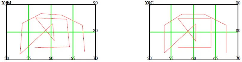
dimensional. In an autonomous situation, the problem is to determine the three dimensional coordinates of a point on the line given its image coordinates. As a solution to this problem, an innovative algorithm is developed to establish a mathematical and geometrical relationship between the physical 3-D ground coordinates of the line to follow and it’s corresponding 2-D digitized image coordinates. The algorithm utilizes a calibration device to determine the focal length of the cameras and the orientation of the projection system with respect to the global coordinates system. The calibration device is constructed to obtain physical co-ordinates of a point on the line with respect to the centered of the robot within an accuracy of 0.0001". From the physical and image coordinates, the camera parameters (coefficients) are computed through a C program subroutine. Figure 4.1 compares the X and Y coordinates for the measured and computed vision calibration sample points. As a result of this reliable performance, the direct coefficients computation model is implemented to solve the vision problem.
Figure 2.1 X and Y measuring for the measured and computed vision calibration point