1
Motion Control Design for Unmanned Ground Vehicle in Dynamic
Environment Using Intelligent Controller
Auday Al-Mayyahi, Weiji Wang, Alaa Hussien and Philip Birch
Department of Engineering and Design, University of Sussex,Brighton, United Kingdom
Abstract
Purpose - The motion control of unmanned ground vehicles is a challenge in the industry of automation. In this paper, a fuzzy inference system based on sensory information is proposed for the purpose of solving the navigation challenge of unmanned ground vehicles in cluttered and dynamic environments.
Design/methodology/approach - The representation of the dynamic environment is a key element for the operational field and for the testing of the robotic navigation system. If dynamic obstacles move randomly in the operation field, the navigation problem becomes more complicated due to the coordination of the elements for accurate navigation and collision-free path within the environmental representations. This paper considers the construction of the fuzzy inference system which consists of two controllers. The first controller uses three sensors based on the obstacles distances from the front, right and left. The second controller employs the angle difference between the heading of the vehicle and the targeted angle to obtain the optimal route based on the environment and reach the desired destination with minimal running power and delay. The proposed design shows an efficient navigation strategy that overcomes the current navigation challenges in dynamic environments.
Findings - Experimental analyses conducted for three different scenarios to investigate the validation and effectiveness of the introduced controllers based on the fuzzy inference system. The reported simulation results were obtained using MATLAB software package. The results show that the controllers of the fuzzy inference system consistently perform the manoeuvring task and manage the route plan efficiently, even in a complex environment that populated with dynamic obstacles. The paper demonstrates that the destination was reached optimally using the shortest free route.
Research limitations/implications - The paper represents efforts toward building a dynamic environment filled with dynamic obstacles that move to at various speeds and directions. The methodology of designing the fuzzy inference system is accomplished to guide the unmanned ground vehicle to the desired destination while avoiding collisions with obstacles. However, our methodology is approached using two-dimensional analyses. Hence, the paper suggests several extensions and variations to develop a three-dimensional strategy for further improvement.
Originality/value - This paper presents the design of a fuzzy inference system and its characterizations in dynamic environments, specifically for obstacles that move at different velocities. That facilitates an improved functionality of the operation of unmanned ground vehicles.
The first author would like to express his gratefulness for his sponsor, the Ministry of Higher Education and Scientific Research in Iraq for funding his PhD scholarship in the United Kingdom. He also would like to thank the University of Basrah in Iraq for the support.
Keywords—Unmanned Ground Vehicle (UGV), Dynamic Obstacles Avoidance, Intelligent Controller, Fuzzy Inference System (FIS)
1. Introduction
Unmanned Ground Vehicles (UGVs) are defined as programmable purpose-built transportation machines, which can gather and extract information from its surrounding using sensors measurements and controllers to plan and execute its mission tasks dynamic environments with limited or no human intervention (Nonami et al., 2013). With the exponential development of technology, nowadays, UGVs have many potential applications in many industries including factories, transportation industry, surveillance and others in daily life. Therefore, decision making and path planning of unmanned ground vehicles require a considerable attention and that is why this topic acquired attention in the last two decades.
The path planning methods are mainly classified into two methods, global planning method and local planning method (Sedighi et al., 2004). For the global planning method, the unmanned ground vehicle requires prior knowledge about the environment and assumes that the terrain is static. In contrast, for the local path planning the environment is partially known or completely unknown. For the local planning method, the unmanned vehicle uses the received real-time sensory information during its local navigation (Wang and Liu, 2005). Therefore, for local navigation, UGVs use sensors to perceive the surrounding environment and plan the motion in real-time. Many researchers have been working on a variety of different techniques to tackle the challenges of path planning and navigation issues in a busy and dynamic environment. For instance, in earlier studies, the potential field method which has been developed as an on-line collision avoidance approach (Khatib, 1986). It is applicable when a UGV or any robotic system does not have any prior model of the obstacles; it senses them during the motion execution stage. A potential function over a free space is defined as the sum of an attractive potential that pulls the robot towards the goal point and a repulsive potential which pushes the robot away from the obstacles. However, even with using graph searching techniques, the potential field method does not always guarantee the attainment of the target and may get stuck at a local minimum.
Intelligent soft computing techniques such as fuzzy control (Cui et al., 2010), artificial neural networks (Chi and Lee, 2011) and hybrid intelligent techniques (Azouaoui et al., 2013; Deshpande and Bhosale, 2013) have been applied widely in solving navigation problems. For instance, path tracking and obstacle avoidance of unmanned aerial vehicle (UAV) using fuzzy logic approach (Dong et al., 2005). In that approach, a UAV with a predefined trajectory should be followed and depending on the actual coordinates; the UAV will detect potential obstacles in its trajectory using sensors. Based on UAV sensors measurements, the fuzzy controller is either activated or de-activated in order to avoid any obstacles. Pradhan et al. (2009) presented a navigation approach for several mobile robots in an unknown environment using a similar fuzzy logic controller. The controller was implemented using a variety of membership functions to navigate these mobile robots in an unstructured environment. However, each robot was represented as a point without considering its dimensions or its dynamic characteristics.
Another method was introduced for an indoor navigation technique using a fuzzy logic control (Rashid et al., 2010). The method proposed the use of the fuzzy logic control (FLC) in the target tracking control for wheeled mobile robots. However, they did not use the FLC to avoid obstacles. Recently, Li and Choi (2013) designed an obstacle avoidance system using a different approach based on a fuzzy logic system. This fuzzy system consists of four inputs and two outputs, but the authors only considered static obstacles and the robot was also represented
3
as a point. Hajar et al. (2013) presented a mobile robot obstacle avoidance using a fuzzy logic technique. The FLC in this work was constructed using eight sensory information inputs and two outputs to control the speed of the robot as well as the turning angle. The workspace environment is built using the Webots Pro simulation software. The simulated environment consists of only static obstacles. Raguraman et al. (2009) proposed a mobile robot that is based on sensor navigation system using a fuzzy logic controller. They proposed a controller with five inputs and two outputs. However, they used a simple static indoor environment. Lwin and Yamamoto (2012), designed a mobile robot controller to pursue a given goal with obstacle avoiding capability. The navigation towards a goal and avoiding a collision with the obstacle constructed based on goal gaining mode and obstacle avoidance mode. These two tasks with different natures are treated under a look-ahead control by simply changing coordinate frames and associated elements.
In state of the art, a neural network controller was proposed for online path planning. The design was based on the feed-forward backpropagation neural network. When a mobile robot finds hurdles in front of it or in its path to the target, the neural network controller will determine the proper turning direction to avoid a collision while heading to the target. However, the reported results were conducted in static environment only. Similarly, autonomous mobile robot navigation in a cluttered environment was investigated using hybrid Takagi-Sugeno fuzzy model and the simulated annealing algorithm controller. The experiments were performed in simple static environments but, the methodology showed an efficient navigation (Pandey and Parhi, 2016a, 2016b). A path planning based on the fuzzy logic controller was introduced in the presence of static and dynamic environments. The controller was able to find a free path with a static environment that contains five obstacles and a dynamic environment that contained three moving obstacles (Cherni et al., 2016). This method will be used for comparison with our approach in terms of optimal operation and a smooth movement while avoiding dynamic obstacles. The existing techniques represent UGV as a single moving point. Therefore, this is considered as constraints on the UGV operation.
Most existing works have been dedicated to the navigation in static environments, rather than dynamic environments. However, industrial applications increasingly need a development for UGV in dynamic environments similar to real world scenarios. In this article, the contributions can be summarised as follows: we proposed a new fuzzy inference system (FIS) to guide the vehicle in a busy and dynamic environment. A full consideration of the UGV and obstacles with different shapes and sizes has been taken. . We considered a random movement of the obstacles in our proposed environment, this created a big challenge to the controller to reach its destination. A new problem statement proposed for the constructing of a dynamic environment where multiple obstacles movements are considered with different speeds and directions.
The fuzzy inference system (FIS) consists of two fuzzy logic controllers which are reactive with the unmanned vehicle navigation commands. The left and right rear wheels are controlled by the proposed two controllers to achieve an ultimate performance with minimum power and to navigate safely, by manoeuvring the moving obstacles, all the way towards its destination with minimum delay. The first proposed controller is reacted based on the sensing information of any objects that are moving near the UGV path or any other obstacles that on the UGV path. The second controller is designed to determine the optimal direction when no obstacles near the UGV platform until the destination point is reached. These two controllers are incorporated into a switching mechanism to choose the operational case that need to be activated. If the UGV senses an obstacle that is approaching its platform, the first controller will be activated but when the path is clear the second controller is
activated. Thoroughly, both controllers allow the UGV to adjust its trajectory in real-time to avoid collisions with any obstacles in the environment while navigating and stop when it reaches its final destination. The major advantage of our design is to achieve an optimal and a smooth path during navigation. This will improve the operation performance of the UGV and avoid the random perturbations, especially when a drift is occuring. The work of this article is organised as follows: Section 2 presents a kinematic model of our unmanned ground vehicle, Section 3 described the design of an intelligent controller based on fuzzy inference system. Section 4 presented the navigation architecture and the dynamic environment model along with the discussion. Section 5 introduces the conducted simulation results with different scenarios to validate the proposed approach; the conclusions are presented in Section 6.
2. Modelling of Unmanned Ground Vehicle (UGV)
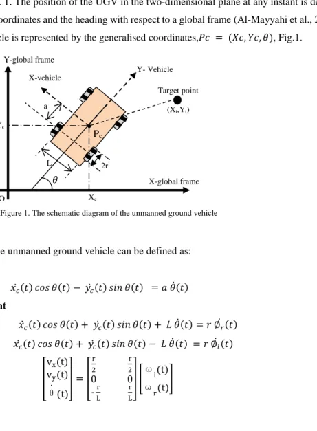
The kinematic model of an unmanned ground vehicle in a two-dimensional plane can be conducted by using Cartesian coordinates. In this work, we assumed that the unmanned ground vehicle moves without slipping on a plane, that means there is a pure rolling contact between the wheels and the ground, and also there is no lateral slip between the wheel and the plane. The UGV has four standard driving wheels and they are differentially driven by skid steer motion. The two rear wheels are independently driven by two motors to acquire flexibility in the motion and orientation. The four wheels have same radius ‘𝑟’. The wheels are separated by distance ‘𝐿’ as shown in the schematic diagram, Fig. 1. The position of the UGV in the two-dimensional plane at any instant is defined by the situation in Cartesian coordinates and the heading with respect to a global frame (Al-Mayyahi et al., 2014). The configuration of the vehicle is represented by the generalised coordinates,𝑃𝑐 = (𝑋𝑐, 𝑌𝑐, 𝜃), Fig.1.
A set of relationships for the unmanned ground vehicle can be defined as: a) No slip constraint
𝑥𝑐̇ (𝑡) 𝑐𝑜𝑠 𝜃(𝑡) − 𝑦𝑐̇ (𝑡) 𝑠𝑖𝑛 𝜃(𝑡) = 𝑎 𝜃̇(𝑡) (1) b) Pure rolling constraint
𝑥̇ (𝑡) 𝑐𝑜𝑠 𝜃(𝑡) + 𝑦𝑐 𝑐̇ (𝑡) 𝑠𝑖𝑛 𝜃(𝑡) + 𝐿 𝜃̇(𝑡) = 𝑟 ∅𝑟̇ (𝑡) (2) 𝑥𝑐̇ (𝑡) 𝑐𝑜𝑠 𝜃(𝑡) + 𝑦𝑐̇ (𝑡) 𝑠𝑖𝑛 𝜃(𝑡) − 𝐿 𝜃̇(𝑡) = 𝑟 ∅̇ (𝑡) (3)𝑙 [ vx(t) vy(t) θ̇ (t) ] = [ r 2 r 2 0 0 -Lr Lr ] [ωl(t) ω r(t) ] (4) X-global frame L -𝜃 Xc Yc Pc 2r Y- Vehicle X-vehicle Y-global frame O Target point (Xt,Yt) a
5 𝑣(𝑡) = 𝑟 [ 𝜔𝑟(𝑡) + 𝜔𝑙(𝑡) 2 ] (5) 𝜃̇(𝑡) = 𝑟 [𝜔𝑟(𝑡) − 𝜔𝑙(𝑡) 𝐿 ] (6) 𝑥̇(𝑡) = 𝑣(𝑡) 𝑐𝑜𝑠 𝜃(𝑡) (7) 𝑦̇(𝑡) = 𝑣(𝑡) 𝑠𝑖𝑛 𝜃(𝑡) 𝜔(𝑡) = 𝜃̇(𝑡) 𝜔𝑟(𝑡) = ∅𝑟̇ (𝑡) 𝜔𝑙(𝑡) = ∅𝑙̇ (𝑡) [ 𝑥̇(𝑡) 𝑦̇(𝑡) 𝜃̇(𝑡) ] = [𝑐𝑜𝑠𝜃 0𝑆𝑖𝑛𝜃 0 0 1] [𝑉𝜔] Where:
Xo is the initial X-coordinate of the UGV Yo is the initial Y-coordinate of the UGV Xt is the X-coordinate of the targeted location Yt is the Y-coordinate of the targeted location Xc is the instantaneous X-coordinate of the UGV Yc is the instantaneous Y-coordinate of the UGV
vx(t) is the longitudinal velocity of the UGV [m/s] vy(t) is the lateral velocity of the UGV [m/s]
θ is the angle of the UGV heading with respect to the x-axis [rad] ωr(t) is the angular velocity of the right wheel [rad/s]
ωl(t) is the angular velocity of the left wheel [rad/s] ω(t) is the angular velocity of the vehicle [rad/s]
𝑎 is the distance between the UGV centre of mass and the driving x-axis of the rear wheel [m].
Since this model describes the velocities rather than the forces, that have an effect on the UGV velocity, we referred this model as a kinematic model. In this article, the radius of the wheels and the distance between them ‘𝐿’ are 𝑟 = 0.1𝑚 and 𝐿 = 0.6𝑚 respectively. The distance between the centre of mass and the rear driving wheels (𝑎) equal to 0.25𝑚.
3. Design of Intelligent Controllers
In this work, the proposed intelligent controller is implemented based on the fuzzy inference system (FIS) (Lee, 1990). The latter is the process of formulating the mapping from given inputs to outputs using a fuzzy logic technique. The mapping then forms the basis from which the decision can be made. The process of fuzzy inference system was based on Mamdani type of inference which involves the following operations of membership functions, fuzzy logic operators and the if-then rules (Driankov and Saffiotti, 2001).
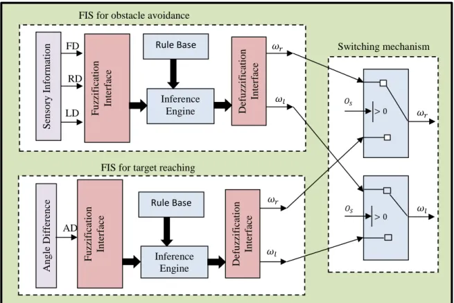
The block diagram of our proposed fuzzy inference system is illustrated in Fig.2. The figure shows two controllers which have been designed and used to accomplish the navigation task of the UGV in the proposed environment. (7) (9) (10) (11) (8)
The obstacle avoidance fuzzy inference system (OA-FIS) controller is designed to avoid collisions with obstacles by using the sensory data. The target reaching fuzzy inference system (TR-FIS) controller aims to make the decision for choosing the optimal direction. Two switches were used to combine the output from the two FIS controllers. The output signal from the first switch was utilised to drive the motor of the right wheel whereas the motor of the left wheel was driven by the signal from the second switch.
The operation of the FIS controllers can be summarised as follows: when there is no obstacle on the UGV path, the TR-FIS controller will be activated to determine the best route for the UGV to take and reach its destination. Whereas, if there is an obstacle on the path of the UGV, the OA-FIS controller will be activated to enable an obstacle avoidance strategy. The switching mechanism between those two controllers will be decided by the measured information from the sensors, (OS) parameter. This OS parameter indicates ‘0’ when there is no obstacle and ‘1’ when the UGV sensors detect any obstacle on the path or any moving objects approaching the UGV path. The outputs of the switching block will be the angular velocities of the right and left wheels of the UGV. These velocities are then fed into the vehicle model in order to obtain the instantaneous UGV coordinates.
3.1.Fuzzy Logic Controller for Obstacle Avoidance
The main objective of this controller is to ensure that the UGV is capable of avoiding collisions when moving obstacles that are diffused in its path. This controller is constructed based on the sensing information that received from the UGV fitted sensors. The sensory information is collected from three sensors. These sensors are fitted on the UGV at three different positions to estimate the distance of the UGV and an obstacle from the left, right and front (LD, RD and FD respectively) as shown in Fig.3. The three estimated distances are fed as an input to the obstacle avoidance controller. Then the obstacle controller produces the angular velocities for the left and right
Figure 2. Block diagram of the proposed two FIS controllers
Def u zz if icatio n In ter fac e Rule Base F u zzif icati o n In ter fac e Inference Engine Sen so ry I n fo rm atio n FD RD LD 𝜔𝑙 Inference Engine Fu zz if icatio n In ter fac e Rule Base Def u zz if icatio n In ter fac e An g le Dif fer en ce AD 𝜔𝑙 𝜔𝑙 𝜔𝑟 𝑂𝑆 𝑂𝑆 > 0 > 0 FIS for obstacle avoidance
FIS for target reaching
Switching mechanism
𝜔𝑟
7
wheels of the UGV which are symbolised as (ωl) for left wheel angular velocity and (ωr) for the right wheel angular velocity. Thus this controller actually regulates the direction of the UGV motion based on the obstacles locations by changing the angular velocities for each of the rear wheels.
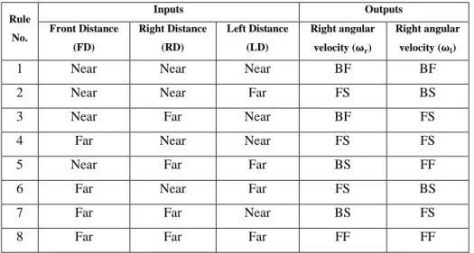
The fuzzy system is implemented with two trapezoidal membership functions for each input variable (LD, RD and FD). The inputs variables for the obstacle avoidance controller are defined as the distance from the left (LD), distance from the right (RD) and distance from the front (FD). We categorised these estimated measurements as either near or far. We designed a fuzzy logic controller for obstacle avoidance using a fuzzy inference mechanism. The knowledge base of the system consists of rules which are written in Table-1. The table shows that the outputs values of LD, RD and FD are combined and translated to generate commands to the motors of the rear wheels based on the following specified angular velocities of ωl and ωr: Backward (BF), Backward Slow (BS), Forward Slow (FS) and Forward (FF). That means each output has five triangular membership functions. The defuzzification process is computed based on the centroid defuzzification technique which is also called centre of gravity (Branson and Lilly, 2001).
Table 1. Rules base of the OA controller Rule No. Inputs Outputs Front Distance (FD) Right Distance (RD) Left Distance (LD) Right angular velocity (𝛚𝐫) Right angular velocity (𝛚𝐥)
1 Near Near Near BF BF
2 Near Near Far FS BS
3 Near Far Near BF FS
4 Far Near Near FS FS
5 Near Far Far BS FF
6 Far Near Far FS BS
7 Far Far Near BS FS
8 Far Far Far FF FF
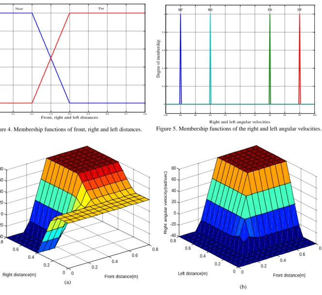
Fig. 4 shows the membership functions of the OA controller inputs which are the sensory information for the left, right and front distances. Fig. 5 shows the membership functions for the outputs of the OA controller which are the angular velocity of the rear right driving wheel and the angular velocity of the rear left driving wheel of the UGV. The surfaces of the three inputs FIS named (FD, RD, and LD) to its first output (right angular velocity)
Front Distance (FD) Left Distance (LD) Right Distance (RD) Obstacle-1 Obstacle-2 Obstacle-3 Sensory information
are viewed in Fig. 6a, b and c. The same surfaces views can be obtained regarding the second output which represents the left angular velocity. The surface viewer simply shows the mapping graphically between any two inputs and output.
0 0.2 0.4 0.6 0.8 0 0.2 0.4 0.6 0.8 -40 -20 0 20 40 60 80 Front distance(m) Right distance(m) R ig h t a n g u la r v e lo c it y (r a d /s e c ) (a) 0 0.2 0.4 0.6 0.8 0 0.2 0.4 0.6 0.8 -40 -20 0 20 40 60 80 Front distance(m) Left distance(m) R ig h t a n g u la r v e lo c it y (r a d /s e c ) (b)
Figure 5. Membership functions of the right and left angular velocities.
-100 -80 -60 -40 -20 0 20 40 60 80 100 0 0.2 0.4 0.6 0.8 1
Right and left angular velocities
D eg ree of memb ers hi p BF BS FS FF 0 0.1 0.2 0.3 0.4 0.5 0.6 0.7 0.8 0 0.2 0.4 0.6 0.8 1
Front, right and left distances
D eg ree of memb ers hi p Near Far
9
3.2.Fuzzy Logic Controller for Target Reaching
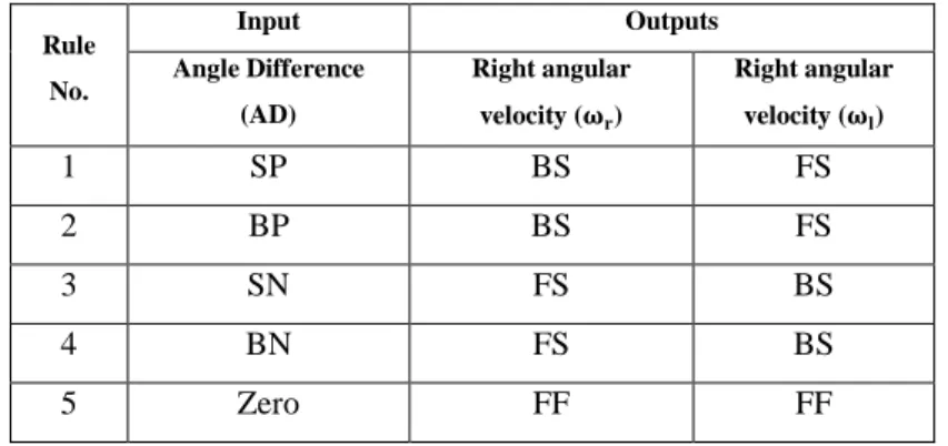
The target-reaching controller is designed to enable the UGV to reach its target destination in the shortest distance. In this section, the FIS controller is implemented using the same principle that we utilised for the obstacle avoidance controller. The input of this controller is an angle which represents the difference between the heading of the UGV and the targeted angle. This angle difference (AD) is computed as shown in Fig.7. The outputs of this controller were obtained using the same technique that we used in obtaining the FIS-OA controller outputs. The input variable of the target reaching controller is the angle difference (AD) which can be big negative (BN), small negative (SN), zero (Z), small positive (SP) or big positive (BP). The output variables are the angular velocities for the rear driving wheels (ωl and ωr) which are categorised as Backward (BF), Backward Slow (BS), Forward Slow (FS) or Forward (FF). Fig. 8 represents the membership functions of the angle difference (AD) input. The membership functions of the target reaching (TR) controller outputs, which are the left and right angular velocities, are same as in Fig.5 given preciously. The rules bases of the target reaching controller are given in the Table-2. The relationships of the surface view between the angle difference (AD) variable and the left and right angular velocities, the outputs of the target reaching controller, are illustrated in Fig. 9. The surface viewer is shown in two-dimension because it only represents the relationship between one input and one output.
𝜃 Vehicle’s heading AD Y-axis ∅ X-axis Target Point Pt (Xt, Yt) Vehicle’sposture Pc (Xc, Yc, 𝜃) UGV Xc Xt Yc Yt
θ = Vehicle’s heading, ∅=Target angle AD =Angle Difference =ሾθ − ∅ሿ
Figure 7. Coordinates at any given point with respect to the target point
0 0.2 0.4 0.6 0.8 0 0.2 0.4 0.6 0.8 -40 -20 0 20 40 60 80 Right distance(m) Left distance(m) R ig h t a n g u la r v e lo c it y (r a d /s e c ) (c)
Figure 6. Surface viewer for the right angular velocity against a) right and front distances; b) front and left distances; c) left and right distances
Table 2. Rules base of the TR controller Rule No. Input Outputs Angle Difference (AD) Right angular velocity (𝛚𝐫) Right angular velocity (𝛚𝐥) 1 SP BS FS 2 BP BS FS 3 SN FS BS 4 BN FS BS 5 Zero FF FF
4. Navigation Architecture and Dynamic Environment Modelling
This section deals with the implementation of the UGV navigation platform and the workspace or the environment implementation. The two fuzzy logic controllers are integrated through a switching mechanism as discussed in the previous section. The outputs of the switching block drive the motors of the driving wheels and move the UGV. When the angular velocities (the outputs) are equal, it means that the UGV will move in a straight line, but if the angular velocities are different, the UGV will be in steering situation either to the right or the left based on the obstacles locations. The dynamic environment of the workspace where the UGV navigates was implemented. The dynamic environment was based on dynamic obstacles in addition to the UGV itself. As shown in Fig. 10 the environment modelling has five inputs and five outputs. The inputs are classified into two groups which are the actual position of the UGV (three inputs) 𝑃𝑐 = (𝑋𝑐, 𝑌𝑐, 𝜃) and the target point coordinate (two inputs).
The outputs of the environment modelling which are the inputs of the controllers and switching boxes are categorised into three groups. First, the sensory information which includes: Front Distance (FD), Right Distance (RD) and Left Distance (LD). This sensory information provides the OA-FIS controller with the necessary information to obtain the accurate angular velocities for the driving wheels for manoeuvring and avoid collisions. Second, the angle difference (AD) which represents the direction of the UGV heading on the targeted destination. This angle feeds the TR-FIS controller as an input to obtain the angular velocities for the rear driving wheels so
-150 -100 -50 0 50 100 150 0 0.2 0.4 0.6 0.8 1
Angle Difference (AD)
D eg ree of memb ers hi p SN Zero SP BN BP
Figure 8. Membership functions of angle difference.
Figure 9. Surface viewer for the angle difference. -500 -400 -300 -200 -100 0 100 200 300 400 500 -40 -20 0 20 40 60 80
Angle Difference (Degree)
A n g u la r V e lo ci ty (r a d /se c)
Left Angular Velocity Right Angular Velocity
11
that the UGV can move in a straight line towards its destination when there is no obstacle in its path. Third, the obstacle sensing (OS) is a switching mode to activate one of two FIS controllers as required, depending on the UGV surroundings. S-function manipulates the interconnection between the inputs and the outputs. This s-function is written in MATLAB for creating a simulation platform for the unmanned ground vehicle navigation and the surrounding environment.
5. Simulation Results
The unmanned ground vehicle platform has been simulated using MATLAB-Simulink to mimic and verify the validity of the controllers based on the fuzzy inference system that discussed in the previous sections. In the simulated platform, different moving obstacles are randomly placed in the workspace. These obstacles are different in size and moving at different velocities. The target destinations of the unmanned ground vehicle were arbitrarily chosen at various places to test the performance of the FIS two controllers for path planning and navigation of the UGV. In this article, we are presenting three scenarios as shown below:
5.1.Scenario I: Obstacles have similar sizes and velocities
In this scenario, in addition to the UGV, there were six moving objects in the environment, as shown in Fig11. These objects were moving at a constant velocity of 2.11 m/s. As a reference, the coordinates of the starting point was marked as the origin 𝑃𝑠 (0, 0) and the coordinates of the destination was𝑃𝑡 (15, 15). Fig. 11 shows that the UGV successfully manoeuvred the obstacles by changing its moving direction and avoided collisions. The target destination was reached by the UGV, which means the TR-FIS controller changed the direction of the UGV movement back to the destination after passing each obstacle. As discussed in the theoretical sections, the decisions to avoid collisions with obstacles were made by the OA-FIS controller according to the distance measurements between the left, right and the front of the UGV and the obstacles. The journey of the UGV from the starting point to the target destination in this scenario took 3.21 seconds. The linear velocity profile of the UGV is shown in Fig.12. Fig. 13 shows the changing in the direction of the UGV while avoiding obstacles.
Figure 10. Block diagram of the proposed FIS for the unmanned ground vehicle. TR-FIS Environment modelling Xt Yt XC 𝜃 YC 𝜔𝑟 𝜔𝑙 Vehicle kinematic FD AD OS Switch in g XC 𝜃 YC RD LD OS 𝜔𝑟 𝜔𝑙 𝜔𝑟 𝜔𝑙 OA-FIS
-2 0 2 4 6 8 10 12 14 16 18 -2 0 2 4 6 8 10 12 14 16 18 Start Point Target Point X-axis (m)
Y
-a
xi
s
(m
)
1 3 5 5 1 2 4 6 6 4 3 2Figure 11. Navigation platform contains of six moving obstacles with constant velocities and similar sizes.
Figure 12. Linear velocity profile for the unmanned ground vehicle in the first scenario.
0 50 100 150 200 250 300 0 1 2 3 4 5 6 7 8 9 Samples V e h icl e ve lo ci ty (m /s ec )
13
5.2.Scenario II: Obstacles have similar sizes but different velocities
In this scenario, shown in Fig.14, the UGV navigation platform was run in an environment where obstacles are moving at different velocities. Obstacles ‘1’ and ‘4’ are moving at a speed of 2 m/s, obstacles ‘2’ and ‘6’ are moving at a speed of 2.8 m/s and obstacles ‘3’ and ‘5’ are moving at a speed of 4.75 m/s. All the six moving obstacles were avoided successfully by the UGV while it was travelling from the starting point towards the destination coordinates. The OA-FIS controller provided the driving wheels with the necessary angular velocities to change the direction of the UGV and avoid collisions with the moving obstacles. A fuzzy rule based on a fuzzy inference mechanism was applied to find the turning angle of the UGV. The decisions were made according to the distance between the left, the right and the front of the UGV with respect to the approaching obstacles. In this scenario, the elapsed time of the UGV journey from the starting point to the destination coordinates was equal to 2.95 s. The linear velocity profile of UGV is shown in Fig.15. Fig. 16 demonstrates the changing in the direction of the UGV while avoiding obstacles.
0 50 100 150 200 250 300 -0.5 0 0.5 1 1.5 2 Samples V e h icl e h e a d in g
Figure 13. Heading changes during the navigation in the first scenario.
(r
ad
Figure 14. Navigation platform contains of six moving obstacles with different velocities but similar sizes. -2 0 2 4 6 8 10 12 14 16 18 -4 -2 0 2 4 6 8 10 12 14 16 18 Start Point Target Point X-axis (m)
Y
-a
xi
s
(m
)
1 1 2 2 3 3 4 4 5 5 6 6 0 50 100 150 200 250 300 0 1 2 3 4 5 6 7 8 9 Samples V e h icl e V e lo ci tyFigure 15. Linear velocity profile for the unmanned ground vehicle in the second scenario.
(m
/s
ec
15
5.3.Scenario III: Obstacles have similar velocities but different sizes
In this scenario, shown in Fig.17, the UGV navigation platform is operated with 6 moving obstacles. The moving obstacles are different in sizes, and their velocities are constant, equal to 1.7 m/s. Fig. 17 shows that the moving obstacles were avoided successfully and the UGV reached the target. The OA-FIS controller avoided the moving obstacles by making decisions on where to change the direction of the UGV. That allowed the UGV to prevent collisions with the obstacles. Obstacle ‘2’ left its original position towards a new position in the workspace. Therefore, its original place became free. The TR-FIS controller is activated when there is no obstacle approaching the UGV. The target destination in this scenario was reached successfully by the UGV after avoiding all the moving obstacles and the elapsed time was equal to 3.58 sec. The linear velocity profile of the UGV is shown in Fig.18. Fig. 19 illustrates the changing in the direction of the UGV while avoiding obstacles. As we can see from Fig. 19 that the size of the obstacles did not impact the performance of the controllers even though larger objects limited the free space in the environment. However, this was accomplished by the accurate distance readings from the UGV sensors.
Figure16. Heading changes during the navigation in the second scenario.
0 50 100 150 200 250 300 0 0.2 0.4 0.6 0.8 1 1.2 1.4 1.6 1.8 2 Samples V e h icl e H e a d in g (r ad )
Figure 18. Linear velocity profile for the unmanned ground vehicle in the third scenario.
0 50 100 150 200 250 300 0 1 2 3 4 5 6 7 8 9 Samples V eh icl e V el oci ty -2 0 2 4 6 8 10 12 14 16 18 -4 -2 0 2 4 6 8 10 12 14 16 18 Start Point Target Point X-axis (m)
Y
-a
xi
s
(m
)
2 6 6 5 1 2 1 5 4 4 3 3Figure 17. Navigation platform contains of six moving obstacles with constant velocities but different sizes.
(m
/s
ec
17
5.4. Comparison with the existing techniques
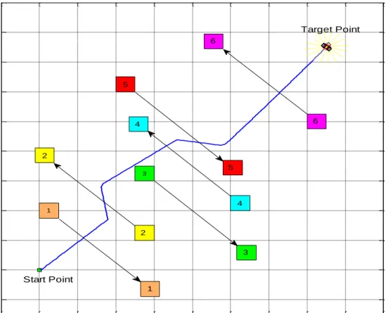
In order to validate the effectiveness of our methodology, we demonstrate comparisons between our approach and an approach that introduced in the state of the art by (Cherni et al., 2016). The comparisons will be conducted based on two different scenarios. The first scenario is considered with three moving obstacles. The starting point is set at (0, 0) and the target point is placed at (8, 9). The three obstacles are positioned at different locations and orientations as shown in Fig.20. It is noticed that the obtained path using our approach is more optimal comparing to the other method. The major advantage of our control system is that the unmanned ground vehicle is able to reach its destination in much shorter path while avoiding obstacles. In addition, the other benefit of our proposed system includes the smoothness of controllers’ commands and its extensibility to compound scenarios.
Figure 19. Heading changes during the navigation in the third scenario.
0 50 100 150 200 250 300 -1 -0.5 0 0.5 1 1.5 2 Samples V e h icl e H e a d in g (r ad )
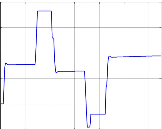
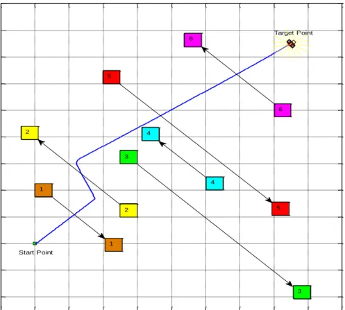
Another comparison is conducted based on a scenario that has obstacles traverse into constant orientations comparison to the previous scenario. This will result into different topology because new coordinates of the obstacles will be occupied as shown in Fig. 21. In additional, the target point has been changed and it is placed at (12, 12). It is noticeable that the new generated path is quite different that Fig.20 in response to the actual motion of the unmanned ground vehicle while navigating. That verifies that the performance of the UGV in different circumstances is capable of an instantaneous localisation and an effective adaption to response to new conditions at any time within its workspace environment. We observe that there is a spike that is closed to the target point. In fact, this is made when the UGV approached to the first obstacle in order to avoid collision with it.
Our approach (Cherni et al., 2016)
2
2
1
1
3
3
Figure 20. Comparison of our proposed approach with (Cherni et al., 2016) method in an environment has three obstacles move into different orientations.
19 6. Conclusions
In this article, two effective fuzzy inference system controllers were proposed to guide an unmanned ground vehicle in a busy and dynamic environment. These FIS controllers supported the unmanned ground vehicle to manoeuvre moving obstacles and avoid collisions. The proposed FIS system consists of two controllers which are the target reaching FIS (TR-FIS) controller and the obstacle avoidance FIS (OA-FIS) controller. These two controllers are based on the reactive behaviour. The TR-FIS controller was proposed to ensure that the UGV reaches its target destination by keeping its heading direction towards the targeted destination when there is no obstacle approaching the UGV. The input of this controller is the angle difference (AD). The OA-FIS controller is responsible for changing the angular velocity of the driving wheel to provide obstacle manoeuvring when an object approach the UGV path. The inputs of this controller are the sensory information that gathered from the UGV sensors. These sensors are attached to the UAV to estimate the distance of any obstacles that are approaching the UGV from the front, right and left.
The control and navigation architecture have been demonstrated in three different scenarios. In the first scenario, six moving obstacles were used; they all have similar sizes and velocities. In the second scenario, the six obstacles were assumed to have similar sizes, but they move at different velocities. In the third scenario, the proposed obstacles were assumed to be in different sizes, but they all have similar velocities. In all scenarios, the unmanned ground vehicle is proved to have the capability of avoiding obstacles and move towards its final
Figure 21. Comparison of our proposed approach with (Cherni et al., 2016) method in an environment has three obstacles move into constant orientations.
Our approach (Cherni et al., 2016)
destination. Therefore, the fuzzy inference system proved to be a satisfactory control methodology for unmanned ground vehicles to avoid moving obstacles in a busy and dynamic environment. It offered an intelligent behaviour in facing the uncertainty issues that are presented by such dynamic environment.
The proposed approach will be implemented on a real UGV system in the next stage of this project to validate our theoretical simulation and demonstrate the behaviour of the proposed controller, experimentally.
References
Al-Mayyahi, A., Wang, W. and Birch, P. (2014), “Adaptive Neuro-Fuzzy Technique for Autonomous Ground Vehicle Navigation”, Robotics, Multidisciplinary Digital Publishing Institute, Vol. 3 No. 4, pp. 349–370.
Azouaoui, O., Ouadah, N., Mansour, I., Semani, A., Aouana, S. and Chabi, D. (2013), “Soft-computing based navigation approach for a bi-steerable mobile robot”, Kybernetes, Vol. 42 No. 2, pp. 241–267.
Branson, J.S. and Lilly, J.H. (2001), “Incorporation, characterization, and conversion of negative rules into fuzzy inference systems”, IEEE Transactions on Fuzzy Systems, Vol. 9 No. 2, pp. 253–268.
Cherni, F., Boutereaa, Y., Rekik, C. and Derbel, N. (2016), “Path Planning for mobile robots using fuzzy logic controller in the presence of static and moving obstacles”, The 3rd International Conference on Automation, Control, Engineering
and Computer Science, pp. 503–509.
Chi, K.-H. and Lee, M.-F.R. (2011), “Obstacle Avoidance in Mobile Robot using Neural Network”, The IEEE International
Conference on Consumer Electronics, Communications and Networks, IEEE, Xianning, China, pp. 5082–5085.
Cui, S., Su, X., Zhao, L., Bing, Z. and Yang, G. (2010), “Study on Ultrasonic Obstacle Avoidance of Mobile Robot Based on Fuzzy Controller”, The IEEE International Conference on Computer Application and System Modeling, IEEE, Tianjin, China, pp. 233–237.
Deshpande, S.U. and Bhosale, S.S. (2013), “Adaptive neuro-fuzzy inference system based robotic navigation”, IEEE
International Conference on Computational Intelligence and Computing Research, IEEE, Enathi, pp. 1–4.
Dong, T., Liao, X.H., Zhang, R., Sun, Z. and Song, Y.D. (2005), “Path Tracking and Obstacle Avoidance of UAVs - Fuzzy Logic Approach”, The 14th IEEE International Conference on Fuzzy Systems, IEEE, Reno, NV, pp. 43–48.
Driankov, D. and Saffiotti, A. (2001), Fuzzy Logic Techniques for Autonomous Vehicle Navigation, Physica-Verlag Heidelberg, New York.
Hajar, S., Mohammad, A., Jeffril, M.A. and Sariff, N. (2013), “Mobile Robot Obstacle Avoidance By Using Fuzzy Logic Technique”, The 3rd IEEE International Conference on System Engineering and Technology, IEEE, Shah Alam, Malaysia, pp. 331–335.
Khatib, O. (1986), “Real time obstacle avoidance for manipulators and mobile robots”, The International Journal of Robotics
21
Lee, C.C.C. (1990), “Fuzzy logic in control systems: fuzzy logic controller, Part II”, IEEE Transactions on Systems, Man, and
Cybernetics, Vol. 20 No. 2, pp. 404–418.
Li, X. and Choi, B. (2013), “Design of Obstacle Avoidance System for Mobile Robot using Fuzzy Logic Systems”,
International Journal of Smart Home, Vol. 7 No. 3, pp. 321–328.
Lwin, Y.Y. and Yamamoto, Y. (2012), “Obstacle-responsive navigation scheme of a wheeled mobile robot based on look-ahead control”, Industrial Robot: An International Journal, Vol. 39 No. 3, pp. 282–293.
Nonami, K., Kartidjo, M., Yoon, K.-J. and Budiyono, A. (2013), Autonomous Control Systems and Vehicles : Intelligent
Unmanned Systems, Springer Tokyo Heidelberg, Japan.
Pandey, A. and Parhi, D.R. (2016a), “New algorithm for behaviour-based mobile robot navigation in cluttered environment”,
World Journal of Engineering, Vol. 13 No. 2, pp. 129–141.
Pandey, A. and Parhi, D.R. (2016b), “Autonomous mobile robot navigation in cluttered environment using hybrid Takagi-Sugeno fuzzy model and simulated”, World Journal of Engineering, Vol. 13 No. 5, pp. 431–440.
Pradhan, S.K., Parhi, D.R. and Panda, A.K. (2009), “Fuzzy logic techniques for navigation of several mobile robots”, Applied
Soft Computing, Vol. 9 No. 1, pp. 290–304.
Raguraman, S.M., Tamilselvi, D. and Shivakumar, N. (2009), “Mobile Robot Navigation Using Fuzzy Logic Controller”, The
IEEE International Conference on Control, Automation, Communication and Energy Conservation, IEEE, Perundurai,
Tamilnadu, pp. 1–5.
Rashid, R., Elamvazuthi, I., Begam, M. and Arrofiq, M. (2010), “Differential Drive Wheeled Mobile Robot (WMR) Control Using Fuzzy Logic Techniques”, The Fourth Asia International Conference on Mathematical/Analytical Modelling and
Computer Simulation, IEEE, Kota Kinabalu, Malaysia, pp. 51–55.
Sedighi, K.H., Ashenayi, K., Manikas, T.W. and Wainwright, R.L. (2004), “Autonomous Local Path Planning for a Mobile Robot Using a Genetic Algorithm”, IEEE Proceedings of the Congress on Evolutionary Computation, IEEE, Potland, USA, pp. 1338–1345.
Wang, M. and Liu, J.N.K. (2005), “Fuzzy Logic Based Robot Path Planning in Unknown Environment”, The EEE
About the authors
Auday Al-Mayyahi received his B.Sc. Degree in Electrical Engineering from University of Basrah in 2003. In 2007, he received his M.Sc. Degree in Power and Machine Engineering from University of Basrah. Currently, he is pursuing the PhD Degree in industrial automation at University of Sussex. His research interests include Robotics, Automation and Intelligent Control Systems.
Weiji Wang received his PhD degree from Oxford University in 1993. Currently, he is a senior lecturer in School of Engineering and Design, University of Sussex. His current research interests include automotive dynamics and control, signal processing and vehicle engineering.
Alaa Hussein is a Teaching Fellow in Electrical and Electronic Engineering at the University of Sussex. He is also a PhD Researcher at the University of Sussex. His current research is addressing the challenge of mitigating orbital debris dilemma in Low Earth Orbit using high power pulsed lasers. Alaa holds a BSc Degree in Control and Systems Engineering and an MSc Degree in Mobile and Satellite Communications.
Philip Birch completed a PhD at the University of Durham in 1999 on Liquid Crystal Devices in Adaptive Optics. He has worked in industry developing rapid prototyping equipment and optical metrology systems. Since working at the University of Sussex, he has been researching computer-generated holograms (CGH), correlation pattern matching, and optical microscopy. He has also worked with industrial partners in image processing, object detection and tracking.