A VSM (Virtual Synchronous Machine) Convertor
Control Model Suitable for RMS Studies for
Resolving System Operator / Owner Challenges
Andrew J Roscoe, Mengran Yu, Adam Dyśko,
Campbell Booth
Department of Electronic and Electrical Engineering University of Strathclyde
Glasgow, UK
Richard Ierna, Jiebei Zhu
National Grid Warwick. UKHelge Urdal Urdal Power Solutions, UK
Abstract— In recent years, it has become clear that reaching the targeted levels of renewable power generation poses problems, not only for basic infrastructure and generation/load balancing, but also in terms of fundamental network stability. In Ireland, the contribution from convertor-connected generation is already constrained to 50-55%, while recent studies of other networks suggest that any “penetration” of convertors above 65% could lead to instability. The phenomena have been observed both in RMS and high-fidelity EMT simulations of convertor-dominated power systems, and appears to be unavoidable when using the dq-axis current-source controllers within conventional grid-connected convertors. The high control bandwidth (>50 Hz) of these convertors also means that they cannot be effectively included within RMS type large-scale network models. The idea of “synthetic inertia” has been proposed in some publications as a mitigating solution but needs to be considered carefully, since if implemented incorrectly it has been shown to further destabilise the network at the critical small timescales and high frequencies. In this paper we present simple versions of a Virtual Synchronous Machine (VSM) model which is implemented and demonstrated in both transient and RMS based simulations. An important aspect of the VSM is that the controller’s bandwidth is low (<<50 Hz). This means that it can be modelled with reasonable accuracy in RMS simulation with time steps of the order of 2ms. From a system operator perspective, large-scale RMS simulations of entire countries or regions containing hundreds of VSM generators can be carried out with reasonable accuracy.
Keywords- NSG (Non Synchronous Generation), Virtual Synchronous Machine (VSM), Convertor Control, Penetration Level Limit, Power System Stability
I. INTRODUCTION
Today all practical models for installed plant presented to the GB (Great Britain) SO (System Operator) and TO (Transmission Operator) for convertor-based generation consist of a dq-axis current-injection (DQCI) mode convertor which references the local system voltages and frequency through a Phase Lock Loop (PLL). For manufacturers and generators this technology offers significant advantages as it is well understood, allows all harvested energy to be exported on to the grid and provides good control of the current flow
which helps with the management of DC rail voltage and current, as well as protection of the various hardware components.
However, with ever growing penetrations of DQCI convertors, for system operators there are various significant areas of concern [1, 2], most notably:
Increased RoCoF (Rate of Change of Frequency)
Loss of synchronising torque/power and reference voltage
Possibility of high frequency instability and controller interaction [3]
Difficulties associated with modelling the electricity systems dynamic behaviour
Reduced and possibly delayed fault in feed
Possibility of voltage instability during or post fault e.g. collapse, blocking or over voltage post fault
Potential for sub-synchronous oscillations and interaction with conventional machines
Potentially increased sensitivity to load imbalance and harmonics
Typically for penetration levels below 50% [1] the remaining conventional synchronous plant provide the appropriate response, mitigating against these effects and allowing normal system operation and modelling. However it is anticipated at some point between 50 and 100% (various estimates exist [4, 5]) one or more of these effects will adversely affect operation and / or modelling.
extremely fast load-side response. Another proposal is to add (or retrofit) “synthetic inertia” to DQCI convertors, which has been termed SEBIR (Swing Equation Based Inertial Response) by the authors in [6]. Effectively the convertor controller attempts to measure frequency, and provide a power modulation proportional to RoCoF and a particular chosen value of synthetic inertia constant H [7-9]. This technique provides what could best be described as a “fast frequency response”, but it does not have the same nature as inertia naturally provided by the synchronous generator (SG). Understanding of this critical difference can be gained by studying the Network Frequency Perturbation (NFP) plots described in [4]. In fact, the authors found in [6] that adding such control loops destabilized the system even more. In addition, it was shown that DQCI (and DQCI with SEBIR) have critical control loop frequencies and oscillatory modes in excess of 50 Hz (i.e. significantly greater than 5 Hz). Instabilities have also been observed in reality in various locations/installations, although [3] is perhaps the only/best example existing in the public domain. Also, some of the lower-frequency modes have been seen by National Grid in their RMS system models [1], and the results have been corroborated with high-fidelity models using time steps of approximately 50μs [4, 5].
It is known that the problem could be avoided by adding synchronous compensators (SC), but there may be questions over whether the use of SCs is an economic long-term solution. However, it has been implemented in conjunction with some HVDC projects, e.g. for Skagerak. An installation was made in 1975 due to a weak AC connection in Norway, and another more recently added in Denmark due to loss of system strength, where conventional generation has been retired and wind output at times exceeds 100% of demand in that part of the much larger Continental European System since 2008.
Although, with the exception of effects on RoCoF, the “synthetic inertia” results using SEBIR were not promising [6]. Much more positive results were obtained by using a convertor control technique the authors refer to as VSM0H (Virtual Synchronous Machine Zero Inertia). This convertor controller resolves many of the pertinent issues, particularly those relating to the loss of synchronising torque/power, voltage reference, and the associated wideband-frequency instabilities [10, 11]. VSM0H has been shown to potentially allow NSG penetration to achieve 100% both in simulation studies [11] and practical systems [12].
As the convertors with VSM0H type controller do not provide an inertial response, further strategies are required to manage the initial value of RoCoF which occurs in the first few cycles following a large generation/load imbalance. This apparent lack of inertia also has to be resolved for the benefit of the remaining synchronous machines connected to the system. However, in terms of frequency excursion containment, the VSM0H strategy has fast-acting frequency droop slope, so active power dispatch is quickly adjusted by VSM0H as the frequency deviation from the set-point increases. In this respect, although it is “inertia-less”, it provides a very good “fast frequency response” and high degree of damping to the existing synchronous machine rotors.
Use of a convertor which is controlled by an algorithm which mimics the dynamic behaviour of a synchronous machine, i.e. a VSM (Virtual Synchronous Machine) [13-17],
is expected to provide many of the benefits of the VSM0H algorithm, plus the ability to deliver “true” inertial support, via choice of an appropriate per-unit inertia constant H. The purpose of this paper is to present potential architectures for such VSM controllers, which can be used in real convertors, and also modelled accurately, using both high fidelity EMT simulation as well as within large RMS type simulation programs.
Two models of the VSM are presented, and the results compared under similar system conditions. The first model is developed in Simulink, using multi-rate EMT simulation (250 μs for the controller frame time; 4 kHz switching, and 50 μs for the average-value power-system model). The second model is an RMS model created for in PowerFactory, and suitable for application with (for example) the National Grid transmission system model. The high-fidelity model is useful when it comes to understanding aspects of power quality and high-frequency device-device interactions, but is also used to corroborate with the RMS model. The RMS model is useful for analysing the large systems. Whilst it is conceivable that improvements in computing technology would allow EMT studies to be performed in detail on a complete power system in the future, it is unlikely that a system operator could ascertain the values of the many thousands of device parameters and software behaviour for the many distributed generators and convertors. Considering these limitations, it is in practice impossible to model the entire system dynamics at bandwidths >5 Hz.
VSM does in many respects behave in a similar manner to a SG (Synchronous Generator) but can potentially deliver some characteristics impossible to achieve in conventional rotating machines due to physical limits. For example, there is nothing to be gained from replicating some of the undesirable characteristics that might otherwise be avoided. VSM may, therefore, outperform SG in some areas, but as convertors are typically subject to stricter design limits such as fault current, harmonics, load imbalance, etc., they may be outperformed by SG in other areas.
Despite these differences, the authors believe it is possible to achieve significant improvements in all 8 areas of concern listed in the introduction, by adopting VSM for at least a proportion of the convertors in a power network.
II. VSM0HCONVERTORS
Whilst VSM0H technology is not the key solution proposed in this paper, as previously stated, it provides essential understanding of the problems being encountered with DQCI, and is therefore, briefly discussed here. It is beyond the scope of this paper to provide a detailed description of the VSM0H technology. However, the key differences between VSM0H, DQCI, and VSM are explained in this section.
the measured powers, based on frequency and voltage droop slopes, set-points of frequency and voltage, and set-points of active and reactive power. If necessary any of these could be changed in real time.
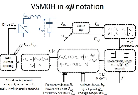
Figure 1 : High-level control diagram for VSM0H convertor controller
The measurements of active and reactive power are filtered using boxcar filters, limiting the system dynamics to have a 3 dB bandwidth of 22 Hz (which is less than 50 Hz). In particular, the filtering places zeros at every multiple of the system fundamental frequency. As a result the voltage source does not react at all to unbalance or harmonics. Even in the presence of harmonics and unbalance, the resulting feedback signals are unaffected and remain clean and true representations of the measured quantities. While no inertia is emulated, the device performs as an “infinite-inertia” device from the perspective of harmonics and unbalance, and it provides a robust, predictable, fast-acting droop-slope response to (for example) frequency and/or under-voltage events.
Because no inertia is emulated, the device makes no attempt to output increased power when frequency first begins to fall - i.e. when there is a finite RoCoF but not yet a finite frequency deviation. However, as soon as the proportional frequency deviation becomes significant, the power output can increase dramatically if the droop-slope is configured to an appropriate value. The fact that no rotor mass is simulated means that there is no damped rotor oscillation. The transfer function is 1st-order and so includes damping but no tendency to resonant. In fact, this means that VSM0H can be used to increase the natural damping within SG and VSM-dominated networks.
As an example of how VSM0H works consider a system only comprising of VSM0H convertors, which experiences an instantaneous 5% load increase. Because all the convertors have frequency droop the system frequency will drop accordingly, however unlike a conventional power system this change will be extremely quick with the majority taking placing in one AC cycle. The system is stable, and there is enough “synchronizing torque” for all VSM0H convertors to remain synchronized. Also, power quality is controlled as all VSM0H-controlled convertors mitigate voltage unbalance and harmonics in proportion to their ratings (which define filter impedances).
III. VSMCONVERTOR MODELS
The output stage of a VSM convertor is very similar to that of a VSM0H. It also is essentially a “true” VSC with the waveform being derived from a model of a rotor with
associated mass and damping. The electrical angle across the per-unit filter impedance X can be written as δ and considered to be equivalent to a rotor angle. Using this analogy, the VSM0H response contains only “spring” (power output is proportional to δ) and “damper” (power output proportional to dδ/dt) terms. The VSM response adds an extra “mass” term - via a finite value of inertia constant H. This term adds a response proportional to d2δ/dt2. This changes the response of the device from a purely damped response, to one with a 2nd -order transfer function with an associated natural resonant frequency determined by:
HX f fn
2 2 2
1 0
(1)
[image:3.595.307.549.235.381.2]A simplified high-level view of the control architecture is shown in Figure 2.
Figure 2 : High-level control diagram for a “true” VSM converter controller
might detract from some of the beneficial inertial response. Further work is required to investigate this.
Therefore, the whole VSM response replicates true VSM performance: it has a bandwidth << 50 Hz, configurable droop settings via a virtual governor, and a damped rotor resonance which provides inertia. The rotor inertia, and the fact that bandwidth is << 50 Hz with a 2nd-order transfer function response, means that the voltage source “induced” by the rotor filters out unbalance (which appears at 2f ≈ 100 Hz and largely does not react to it) and harmonics which appear at higher frequencies. Like the VSM0H, the true VSM produces a robust balanced 3-phase voltage set which mitigates voltage power quality problems in a manner proportionate to its rating and filter reactance X.
The fact that virtual-rotor resonance occurs at frequencies <= 5 Hz is important, because it means the control bandwidth is limited to <= 5 Hz. This 5 Hz figure was chosen as it is the current GB Grid Code limit for SG [2] and exists largely to protect synchronous plant from exciting torsional shaft oscillations.
Some care needs to be exercised when referring to literature concerning VSM. In the same way that the term “synthetic inertia” is ambiguous in its detail, some “VSM” implementations actually have inner dq-axis current control loops (e.g. [18]) and may not provide many of the benefits of VSM listed in this paper.
During close-in faults, action needs to be taken to avoid convertor destruction, as it is operated as a voltage source. This intervention is described in [19] and has the advantage that it can service unbalanced, resistive and non-linear fault currents, rather than the “balanced reactive current” prescribed by existing grid codes. The fault current limiting does not affect the behaviour of the underlying VSM model, which has bandwidth < 5 Hz. Further work is needed to provide practical limits of NPS and harmonics performance to preserve enough of the converter’s capability in order to provide the prime purpose of power conversion.
Modification’s such as the inclusion of dynamic braking, which on synchronous machines involves the addition of expensive plant such as resistor banks, are simply implemented in software. This reduces the post fault power oscillations, increasing system stability, minimizing increases to the convertor rating requirements (see Figure 9 and Figure 10), and allows the convertor to survive distribution fault durations in excess of 500 ms (see Figure 10).
It should also be noted that any renewable energy source connected to a VSM would have to be capable of supplying the necessary changes in power and would require an increased convertor rating. In practice, due to lack of control of the common energy sources such as wind and solar, it is likely that some storage would be necessary, or for a generation source to operate at reduced power output in order to provide headroom for any additional energy demanded by the convertor. Both of these solutions could have significant commercial implications, although the amount of storage required is relatively small.
The broader system based advantages with early widespread application of VSM as well as the additional equipment implications are discussed further in section VI and also in [20].
IV. IMPLEMENTATION OF VSMMODELS
Many aspects of the VSM model implementation in MATLAB and PowerFactory are the same. Both models consist of 6 major subsystems: power droop governor, reactive power droop voltage controller, rotor inertia emulation, dynamic braking, output current limiter and waveform generator. The first 4 of these subsystems are implemented identically in both models and described in this section. The current limiter and waveform generators differ and are described individually in the following sections.
Figure 3. Power droop governor model for the VSM
Figure 4. Voltage regulator model for the VSM
The power droop governor is shown in Figure 3 and uses a PI (Proportional and Integral) controller and low pass filter (LPF) with a gain which represents the gain and fuel/control system delay of a mechanical governor. The MATLAB model is essentially the same but includes an optional 1/(1+s.Td) term in the path of pdroop to improve the response during large load steps.
The voltage controller is configured as shown in
Figure 4 with similar design as the governor controller. Reactive power output is measured and multiplied by the voltage droop gain and then subtracted along with the feedback voltage (taken after the output filter) from the voltage reference. The resulting error signal is processed by a PI controller and mixed with an optional power system stabilising signal. The resulting summed signal is passed through a LPF and gain to simulate the gain and field time constant of a SG. This signal is passed to the current limiter which normally doesn’t change it and then to the convertor output oscillator to set the output voltage on the convertor side of the filter reactance.
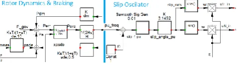
[image:4.595.309.548.705.771.2]Figure 5. Emulation of rotor dynamics
Various damping signals were therefore added and these can be used individually or in combination. The dm term is the equivalent of
mechanical damping in SGs but unlike the SG there are no real losses incurred from increasing it. However, doing so adversely affects the steady
state gain. The de term has a similar affect but has the benefit of leaving
the steady state gain intact. It is derived from the speed feedback signal. The sde term performs the same function as de but in practice would not experience measurement noise and is the main damping signal applied in
the results. Finally, the model provides a vde option which modifies the
voltage in similar fashion to a PSS on an SG (not shown). This is derived in the same way as the psde signal but is added to V_err in the voltage
controller (see
Figure 4). It also works very well and unlike PSS on SG is applied at a point where no phase compensation was required. However, unlike the other options it affects the terminal voltage and was switched off for the results presented here.
Dynamic braking is applied in both models which consists of a switch placed before the 1/2Hs term. This opens for convertor terminal voltages of less than 0.85 pu. This prevents the integrator changing the frequency of the convertor and advancing the operating angle when close up faults are applied. The 0.85 pu was chosen as the GB grid code allows generators to trip if this is exceeded for more than 1.5 seconds [2].
A. Implementation of VSM within MATLAB Simulink
The MATLAB EMT model runs at 50 μs (250μs for the controller frame time) where 3-phase AC waveforms are generated by the power system and the various components within it. The model is therefore capable of simulating the effects of imbalance, harmonics and better represents the hardware than the equivalent RMS model.
An average value model for a VSC convertor with controllable sources is utilised to represent the convertor interface, where the switching effect is replaced by its average effect over the PWM switching cycle. The switching inter-harmonics generated by the switching process are neglected. The final drive voltages Eabc computed from the VSM
controller are sent to the controllable voltage sources for 3-phase waveform generation at the output. For the operation of VSC convertor and its control system, the following delays (at its corresponding sampling time step) are simulated in the MATLAB model: an 0.5 frame delay for the simulated averaging of multiple ADC (Analogue to Digital Converter) reads across the whole of the preceding frame, a 1 frame delay in due to real-time computation, and a 0.5 frame delay due to the use of PWM (Pulse Width Modulation) switching pulses. For the VSM algorithm proposed in this paper, it is crucial to ensure the correct amount of phase advances are applied on the derived rotor angle to compensate for the delays, i.e. 1 frame phase advance for feedback signals in the controller and 2 frames for calculation of the final drive voltages.
Single-cycle boxcar filters are implemented to the measured rotor angle (from the actual electrical power output of the VSM) and after rotor angle derivation for better signal quality. The current limiting block described in [19] is applied in the MATLAB model to avoid damage to the convertor, which is fast acting and capable of providing balanced or unbalanced fault current.
B. Implementation of VSM within PowerFactory
The diagram in Figure 5 shows the output stage for the PowerFactory VSM model. This model differs from the MATLAB version as it uses the “Statgen” element type in PowerFactory as the basis of the convertor interface to the network. This is the same element used for DQCI models, however for a VSM convertor the “Statgen” element is configured in Voltage source mode. DQCI models, by contrast, configure it as current source and use a PLL to provide a phase reference to the network.
[image:5.595.310.539.342.413.2]PowerFactory RMS studies operate with fixed reference frame. PowerFactory provides two signals, u1r_in (v real) and u1i_in (v imaginary), for controlling the voltage source which under nominal frequency and steady state conditions are static. Unlike the MATLAB model, which has a three phase voltage reference generator operating at the system frequency, the 50Hz signal is effectively removed from the PowerFactory simulation and replaced by quadrature RMS voltages. Consequently in the PowerFactory the simulation of the 50 Hz oscillator is replaced with a slip frequency oscillator which operates at the difference between the actual and nominal system frequencies. 1 pu system frequency is subtracted from the input signal taken from the rotor simulation to provide the slip frequency which then rotates the quadrature voltages at the slip frequency.
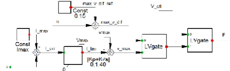
Figure 6. Current limitation applied in the PowerFactory model
The PowerFactory current limit is shown above in Figure 6 and consists of two LV gates which connect the lowest, of the two input signals to their outputs. Normally the voltage regulator signal is selected and used to determine the convertor output voltage. Under short circuit conditions the output voltage is initially prevented from exceeding the terminal voltage by more than 15% which limits the current to about 1.5 times rating as the convertor output reactance is 10%. After a short delay a PI reactive current controller becomes active and takes further action to limit the current to a specified value of 1.25 pu rated current.
V. ELECTRICAL NETWORK AND TESTS
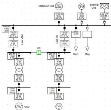
Figure 7. Network model in PowerFactory, including a VSM
A. 5% Voltage step
Figure 8. Test A: 5% Voltage step at SG and VSM
For this case study, a 5% voltage step is applied to the voltage reference signal in SG and VSM control system. Both SG and VSM terminal volts have a fast response with no overshoot on the VSM. Both of the generators experience power oscillations which are highly damped either by the damping mechanism in VSM and power system stabiliser (PSS) for SG. The VSM experiences slightly more power oscillations for the case shown, however these can be damped further by increasing the electrical damping factor sde and there is no need for a PSS. Results from the MATLAB model are also shown for comparison with those from the PowerFactory model. The PowerFactory results were produced from an RMS simulation, whilst the MATLAB results are based on EMT simulation. Note: Because the VSM models are built in different software and use different techniques the results are generally similar but have some differences.
B. 140ms short-circuit fault at the grid connection point To test performance for Type A transmission faults, a 140ms 3ph short-circuit is applied at the grid connection point on the HV side of both transformers. Both generators behave satisfactorily and can recover after the fault is removed. Regarding fault in-feed, the SG outperforms the VSM which current limits, initially at 1.5pu. After a short time, current reduces to an average of 1.25pu, as can be seen from the trace
it’s very quick and hunts about 0.1pu. The SG by contrast produces four times the reactive power. However, the retained voltage is twice as high on the SG, result in in double the fault current for a close up fault. Because the SG is a voltage source behind an impedance and the VSM is essentially in constant current mode the difference will reduce the more distant the fault. Both currents reduce with time. On the VSM this is due to the PI controller and on the SG the transient and sub-transient reactance. Although the retained voltage on the VSM is very low, the fault in feed current was closer to the SG than expected. The SG current is limited at 2.5 pu naturally by the impedance of the transformer. Dynamically the VSM outperforms the SG as the dynamic braking is applied to the 1/2Hs term for voltages below 0.85 pu, which is not only beneficial for the power system as a whole but it is also necessary for practical and economic convertor design as limits the power required post fault.
Figure 9. Test B: 140ms TSO fault at the grid connection point
C. 500ms short-circuit fault at the low voltage (LV) side of the transformers
Figure 10. Test C: 500ms TSO fault at LV side of the transformers
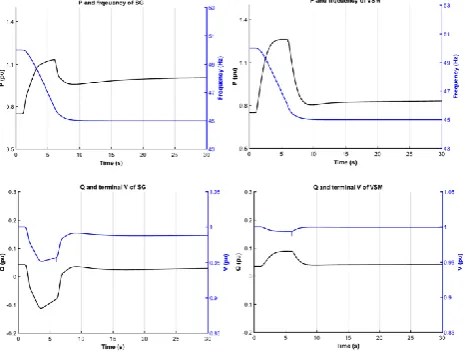
D. 1 Hz/s frequency ramp from 50Hz to 45 Hz
[image:7.595.52.285.226.402.2]With the inertia simulated, i.e. the 1/2Hs term, the response of the VSM to the 1 Hz/s frequency ramp is similar to that of the SG. At the instance when the frequency starts to ramp, the P outputs from the two generators ramp up. The increased power largely results from the real or simulated inertia. The height of the pulse being proportional to df/dt. The slope on the top of the power pulses and increased settling values on completion of the ramp are due to governor action. The settled P levels are different due to the different limit settings in the VSM governor. For the SG, the voltage fluctuates due to the PSS response to power changes, whereas the VSM is less affected and incurs less voltage disturbance.
Figure 11. Test D: 1 Hz/s frequency ramp from 50 Hz to 45 Hz
VI. ADVANTAGES OF VSMCONVERTOR CONTROLS
Regarding the 8 areas of concern for existing DQCI convertors, which were initially raised in the introduction, the VSM controllers presented here typically out performs existing DQCI controller:
Increased RoCoF. Software emulation of inertia in VSM
assists with RoCoF and additionally ensures compatibility with existing SG.
Loss of synchronising torque/power and reference
voltage. Under normal circumstances, VSM provides
synchronising power and a reference voltage for other VSM, SG & DQCI based generation but VSM may introduce classical oscillatory modes of power system instability, as experienced by SG. However, these are well understood and can be tackled using either the conventional control analysis methods, or new techniques some of which are described here.
Possibility of high frequency instability and controller interaction. Limiting the bandwidth of the control signals significantly reduces the risks of high frequency instability and controller interaction. Potential risks regarding convertor protection still remains, as this must operate quickly. This is applicable to all convertors and is not VSM specific.
Difficulties associated with modelling the electricity
systems dynamic behavior. VSM and VSM0H convertors
of the type discussed here can be modelled using RMS
simulations, using the described techniques, making large system studies possible.
Reduced and possibly delayed fault in feed. In common
with existing converters, a converter operating as a VSM will still be constrained to the maximum instantaneous current limit allowed by the solid-state devices. However, VSM technology allows faster and more appropriate fault in-feeds to be made. The currents rise within 1 cycle, and can provide unbalanced fault current at whatever power factor(s) the fault impedance(s) draw [19].
Possibility of voltage instability during or post fault e.g. collapse, blocking or post-fault overvoltage. The delivery of reactive power from VSM during a fault, unlike DQCI, is driven by the network and not the controller which largely maintains its pre-fault operating angle but reducing its voltage output in order to limit the current. This has the additional advantage that the reactive power naturally reduces on fault clearance reducing the risk of post-fault overvoltage. Many convertors currently block (i.e. produce no output) when the voltage falls below 20-40% of the nominal value. On a weaker system, where fault levels are reduced, this is of greater concern and the blocking voltage may need to be reduced or eliminated.
Potential for sub-synchronous oscillations and
interaction with conventional machines. The 5 Hz band
width limit is in part driven by the assumptions that sub-synchronous and torsional oscillations occur between 4 and 50 Hz [21]. The examples provided here significantly attenuate all signals at and above 4 Hz.
Potentially increased sensitivity to load imbalance and
the harmonics. The 5 Hz bandwidth limit effectively decouples the measurement and feedback signals from the waveform generation, allowing greater time for measurement with the potential to mitigate the effects of imbalance and harmonics on the measurements. The output stage of this type of convertor attempts to produce a three phase balanced voltage waveform. When connected to a system where external harmonic or unbalanced voltage and / or currents are present, these result in additional harmonic or unbalanced load current in the convertor. In principle, from a system perspective, the absorbing of some of the harmonic and unbalanced currents is desirable. However, the “soaking up” of voltage unbalance (fundamental or harmonic), results in a power modulation at the DC side of the convertor and may lead to higher capacitor dV/dt ratings, as for example indicated in [22]. It is foreseen that strategies might be implemented which allow for harmonic or imbalance within specific design limits and then control actions, such as modifying the phase amplitudes or output wave shape, may be permitted to reduce the adverse effects. These might be implemented so as to not impair the advantages VSM provided that a bandwidth limit on such control actions exists to prevent them interacting with other control systems both within the VSM and external to it. For example limiting the bandwidth to 5 Hz would largely maintain the integrity of the proposed solution. Further limiting to 0.05 Hz would have the advantage of placing any such actions beyond traditional power system instability.
VII. CONCLUSIONS AND FURTHER WORK
With power system portfolios changing rapidly and with increasing instantaneous penetration level of convertors in the power networks, ensuring satisfactory and secure operation is becoming more challenging. Recent studies have shown instability of the power networks when the penetration of conventional DQCI convertor reaches beyond ~50%, due to the reduced system strength and wide range of modes and frequency bandwidths in the convertor controllers. Former work by the authors have investigated the VSM0H converter control technique with no inertia emulated, these have proved to have the great benefits on power quality as well as stability. In this paper, a VSM architecture is proposed, which provides benefits of the VSM0H converter, plus dynamic braking, inertia and damping emulation. Although the VSM behaves in a similar manor to the SG, it can outperform SG in various aspects since its parameters are not constrained by the physical design, cost or mechanical/ practical considerations and is therefore possible control and achieve specific desired behaviours, which can be advantageous for both operational and economic considerations.
The VSM convertor presented here has the potential to increase the penetration level limits of convertors in a power network to 100% [20]. Based on various case studies, these results demonstrate that the VSM convertor response can be sufficiently accurately modelled using RMS simulation in PowerFactory. Therefore, RMS-based models, in many cases, are sufficient for studying wider power system challenges on larger networks, if they contain sufficient SG and/or VSM-equipped converters to assure high-frequency stability (which is difficult to model in the RMS simulation).
REFERENCES
[1] H. Urdal, R. Ierna, J. Zhu, C. Ivanov, A. Dahresobh, et al., "System strength considerations in a converter dominated power system," IET Renewable Power Generation, 2015.
[2] National Grid (UK), "The Grid Code," 2016.
[3] C. Buchhagen, C. Rauscher, A. Menze, and D. J. Jung, "BorWin1 – First Experiences with harmonic interactions in converter dominated grids," in International ETG Congress, Bonn, 2015, p. 7.
[4] M. Yu, A. J. Roscoe, A. Dyśko, C. D. Booth, R. Ierna, et al., "Instantaneous Penetration Level Limits of Non-Synchronous Generation in the British Power System," IET Renewable Power Generation, 2016.
[5] M. Yu, A. Dyśko, C. Booth, A. J. Roscoe, J. Zhu, et al., "Investigations of the Constraints relating to Penetration of Non-Synchronous Generation (NSG) in Future Power Systems," in Protection, Automation & Control World Conference (PACWorld), Glasgow, UK, 2015.
[6] M. Yu, A. Dysko, A. J. Roscoe, C. Booth, R. Ierna, et al., "Effects of Swing Equation-Based Inertial Response (SEBIR) Control on Penetration Limits of Non-Synchronous Generation in the GB Power System," in IET Renewable Power Generation (RPG), Beijing, China, 2015.
[7] M. A. Torres, L. A. C. Lopes, L. A. Moran, and J. R. Espinoza, "Self-Tuning Virtual Synchronous Machine: A Control Strategy for Energy Storage Systems to Support Dynamic Frequency Control,"
IEEETransactions on Energy Conversion, vol. 29, pp. 833-840, Dec 2014.
[8] J. Zhu, C. D. Booth, A. P. Grain, A. J. Roscoe, and C. G. Bright, "Inertia Emulation Control Strategy for VSC-HVDC Transmission Systems," IEEE Transactions on Power Systems, vol. 28, pp. 1277-1287, 2013.
[9] M. Y. Guan, W. L. Pan, J. Zhang, Q. R. Hao, J. Z. Cheng, et al., "Synchronous Generator Emulation Control Strategy for Voltage Source Converter (VSC) Stations," IEEE Transactions on Power Systems, vol. 30, pp. 3093-3101, Nov 2015.
[10] L. D. Zhang, L. Harnefors, and H. P. Nee, "Power-Synchronization Control of Grid-Connected Voltage-Source Converters," IEEE Transactions on Power Systems, vol. 25, pp. 809-820, May 2010. [11] M. Yu, A. J. Roscoe, C. Booth, A. Dysko, R. Ierna, et al., "Use of an
Inertia-less Virtual Synchronous Machine within Future Power Networks with High Penetrations of Converters," in 19th Power Systems Computation Conference (PSCC), Genoa, Italy, 2016. [12] A. Engler, "Applicability of droops in low voltage grids,"
International Journal of Distributed Energy Resources and Smart Grids, 2005.
[13] Q. C. Zhong and G. Weiss, "Synchronverters: Inverters That Mimic Synchronous Generators," IEEE Transactions on Industrial Electronics, vol. 58, pp. 1259-1267, Apr 2011.
[14] Q. C. Zhong, G. C. Konstantopoulos, B. Ren, and M. Krstic, "Improved Synchronverters with Bounded Frequency and Voltage for Smart Grid Integration," IEEE Transactions on Smart Grid, 2016. [15] M. P. N. Wesenbeeck, S. W. H. de Haan, and P. Varela, "Grid tied
converter with virtual kinetic storage " in IEEE PowerTech, Bucharest 2009.
[16] R. Aouini, B. Marinescu, K. Ben Kilani, and M. Elleuch, "Synchronverter-Based Emulation and Control of HVDC Transmission," IEEE Transactions on Power Systems, vol. 31, pp. 278-286, Jan 2016.
[17] M. Ashabani and Y. A. R. I. Mohamed, "Integrating VSCs to Weak Grids by Nonlinear Power Damping Controller With Self-Synchronization Capability," IEEE Transactions on Power Systems, vol. 29, pp. 805-814, 2014.
[18] S. D'Arco, J. A. Suul, and O. B. Fosso, "A Virtual Synchronous Machine implementation for distributed control of power converters in Smart Grids," Electric Power Systems Research, vol. 122, pp. 180-197, May 2015.
[19] A. J. Roscoe, G. Jackson, I. M. Elders, J. McCarthy, and G. M. Burt, "Demonstration of Sustained and Useful Converter Responses during Balanced and Unbalanced Faults in Microgrids," in IEEE
International conference on Electrical Systems for Aircraft, Railway and Ship Propulsion (ESARS), Bologna, Italy, 2012.
[20] R. Ierna, A. Roscoe, M. Yu, H. Urdal, A. Dyśko, et al., "Effects of VSM Convertor Control on Penetration Limits of Non-Synchronous Generation in the GB Power Sytstem," in 15th Wind Integration Workshop, Vienna, 2016.
[21] "IEEE Guide for Identification, Testing, and Evaluation of the Dynamic Performance of Excitation Control Systems," IEEE Std 421.2-2014 (Revision of IEEE Std 421.2-1990), pp. 1-63, 2014. [22] A. J. Roscoe, S. J. Finney, and G. M. Burt, "Tradeoffs between AC