Analysis Of Grid Connected Dfig With Variation In
Generator Speed And Stator Reactive Power Demand
Using Reference Power Based Improved Field
Oriented Control
D.V.N. Ananth, G. Joga Rao
ABSTRACT: In general electrical generators are designed to operate at optimal loads and other operating points to have better efficiency, lesser losses and good voltage regulation. For this the doubly-fed induction generator is also developed in such a way to have better real and reactive power flows, lesser losses and higher productivity. The reactive power supply from the wind power based generators and its associated converters are helpful in improving the profile even under normal operation or under grid faults. The requirement for the reactive power also increases with increase in penetration of these renewable sources or under severe grid faults. In this paper, source and grid side disturbances are analysed such as variable wind speed, rotor speed, and grid reactive power. With any type of disturbance, the DFIG parameters must be stable and to follow the reference parameters. To do so, reference power based improved field oriented control (RPIFOC) scheme is proposed and in this, the stator and rotor reactive powers are controlled based on stator real power value using lookup table technique. The inner control loops also perform faster so as to react with varying disturbances and to follow the desired reference values. For analysis, DFIG parameters like rotor power, grid and stator power, generator speed, stator and rotor currents are considered along with mechanical parameters. The simulation results are done with MATLAB/ SIMULINK.
Index Terms: Doubly Fed Induction Generator (DFIG); wind energy conversion system (WECS); Back-to-back converter; reactive power control; maximum power extraction; sub-synchronous spee
NOMENCLATURE
DFIG parameters
and Stator leakage reactance, Stator and Rotor resistance, Rotor, magnetizing reactance
, , , , , , , , , , two axis stator and rotor voltage, current, and flux
Revised Manuscript Received on April 17, 2019.
D.V.N. Ananth, Assistant Professor, Department of EEE, Raghu Educational Society, Visakhapatnam, India,
G. JogaRao, Associate Professor & HOD,Department of EEE, Raghu Educational Society, Visakhapatnam, India,
and is stator flux during fault and during steady state in stationary reference frame
is stationary reference frame rotor voltage and induced rotor voltage in stationary frame of reference
Stator and Rotor real and reactive power
Stator, Rotor and arbitrary speed Electromagnetic torque (EMT)
s slip speed of DFIG
pu per unit
I. INTRODUCTION
In general, the DFIG system is a double excited, by which both the stator winding and the rotor windings will pump active and reactive power to the grid based on generator rotor speed [1]. The flow of real and reactive power in the rotor reverses. During this process the stator real power flow will not get affected. The rotor delivers real and reactive power to the grid or receives the reactive power when generator operates in sub-synchronous speed. During this process of speed improvement from sub-synchronous to super-synchronous speed, care has to be taken such that no surge voltage or current is produced, which damages the rotor windings. The rotor needs to run at super-synchronous speed to have better efficiency and hence low losses and heat. So, the study on the effect of change in rotor speed, wind speed and reactive power on the DFIG performance is very important. With increase in the wind speed, which improves the input to the wind turbine increases, hence maximum power extraction from the generator- turbine set is improved. If the rotor is made to run at optimal speed with better MPPT technique, maximum real power extraction is done. MPPT at sub-synchronous and super-synchronous speed with pitch angle controller and optimal power coefficient is described in [2] and with direct and indirect reactive power control techniques to extract the powers equal to its reference [3]. The DFIG is a doubly fed device, which can deliver both real and reactive power from both stator and rotor [4-9]. The power flow direction and its
magnitude from the stator
economic operation of DFIG [4]. The real and reactive power will be always from stator to the grid, while the rotor side power flow will be towards the rotor from the grid when the rotor speed is lesser than the synchronous speed, and power flow from the rotor towards the grid, when the DFIG operated above the synchronous speed. So, to have optimal electrical power flow, rotor speed of rotation plays a major role. For getting maximum mechanical power from the turbine, rotor blades adjustment, sweeping angle and speed under aerodynamics standards are very important [5, 6].
If more wind generators couple to the grid leads to penetration issues causes many problems to sensitive generators [7]. The solution to above penetration issue for making healthy system is effective control of reactive power [8, 9]. A neural network based adjustable speed drive is analyzed for maximum power transfer functioning in [10] and a sensor-less based MPPT is demonstrated in [11]. The performance of DFIG is discussed under variable rotor speed positions [12], improved efficiency and performance is illustrated by author Rahimi Mohsen for DFIG based system recently in [13]. The same author also proposed a technique for RSC and GSC to have better reactive support and good voltage regulation [14]. Different techniques are proposed in [15-17] to improve the performance of DFIG during variable reactive power and to get maximum power from the generator-turbine set. Different ways of real and reactive power flow in DFIG with different techniques like sliding mode control [18], particle swarm optimization [19] and different techniques [20-24] are discussed by many authors. In these papers, exact control of real and reactive power flow in DFIG as per the reference value and further without surges and ripples during sharp changes, there is a considerable deviation.
The main features of the proposed improved field oriented control in comparison with conventional field oriented control are:
a) limiting the stator current ripple
b) rotor speed is almost constant as per the given reference value
c) Electromagnetic torque surges and
oscillations during wind speed changes is very small and negligible
d) minimized ripples and fluctuations in the stator active and reactive power
e) Compared to conventional FOC, proposed IFOC is better in improving the dynamic behavior under natural disturbances like wind speed and reactive power changes.
f) Reducing the ripple in electromagnetic torque and stator reactive power
In this paper reference power based improved field oriented control (RPIFOC) is proposed and studied under three case studies. The RSC is designed based on the lookup table mechanism for effective operation of DFIG and to make the rotor to run at optimal speed and to extract maximum power from the generator turbine set. The lookup table is designed based on the analytics described in the paper in section 3. The
dc link across the capacitor and control of the reactive power are major roles of GSC controller. The paper is sorted as follows: mathematical modeling is dealt in section II; rotor side controller (RSC) and grid side controller (GSC) architecture and design is described in section III; Four case studies like i) random varying wind speed, ii) generator rotor speed, iii) grid reactive power requirement and iv) increasing wind speed is analyzed in section IV. Section V concludes the main contributions, followed by appendix and references.
II. MATHEMATICALMODELLINGOFDFIG
The mathematical modeling for the internal control loop of RSC of DFIG, control parameters for rotor speed and reactive power are discussed in detail in this section.
A. Mathematical Modelling of DFIG for reference power based improved field oriented control (RPIFOC) scheme
The DFIG equivalent circuit in dq-synchronous reference frame with rotor side reference as in reference [5] is considered in this paper. The stator voltage as a function of stator flux ψs is given by (1). The nomenclature of these machine and grid parameters is described in the nomenclature at the starting.
;
ds s s s s
V
(1)s slip s
s s r s
r
L
X
L
s
X
;
;
(2)These basic equations of DFIG are taken from the reference [3 and 6]. The d and q axis stator and rotor voltages are given by the equations (2a) to (2d)
ds qs
s ds s ds
R
i
V
(2a)qs ds
s qs s qs
R
i
V
(2b)dr qr
slip dr r dr
R
i
V
(2c)qr dr
slip qr r qr
R
i
V
(2d)Here
P representsdt
d
The stator and rotor two axis d and q flux components defined as a function of stator and rotor currents is shown below.
dr m ds s
ds
L
i
L
i
(3a)
qr m qs s
qs
L
i
L
i
(3b)
ds m dr r
dr
L
i
L
i
(3c)
qs m qr r
qr
L
i
L
i
(3d) Further, the stator and rotor inductance is shown below, where leakage and mutual parameters are in series and so additive.
Now using the
equations (3a) and (3b), the m lr r m ls
s
L
L
L
L
L
represented by the equation (4) as
]
[
1
]
[
1
qr m s qs dr s m s s dr m ds s dsI
L
L
I
I
X
X
X
V
or
I
L
L
I
(4)Now the rotor voltage equations as a function of stator and rotor currents by replacing the rotor flux parameters to extract a relationship with rotor currents and main stator voltage. Substituting equations (3c) and (3d) in (2c) and (2d), the equations (2c) and (2d) will become
ds m qs m slip qr r slip dr r r
dr
R
L
i
L
i
L
i
L
i
V
(
)
(5a)
Substituting equation (4) for stator currents in the equation (5a), the rotor d-axis voltage becomes
ds s m qr r slip dr r r dr
L
L
i
L
i
L
R
V
(
)
(5b)Replacing the stator d-axis flux from equation (5b) using equation (1), this (5a) will become
s s s m qr r slip dr r r dr
V
L
L
i
L
i
L
R
V
(
)
(5c)The leakage factor σLr can be stated as 1+ . Similarly, deriving the equations for q-axis rotor voltage, the equations are qs m ds m slip dr r slip qr r r
qr
R
L
i
L
i
L
i
L
i
V
(
)
(5d) ds s m slip dr r slip qr r r qr
L
L
i
L
i
L
R
V
(
)
(5e) ands s s m slip dr r slip qr r r qr
V
L
L
i
L
i
L
R
V
(
)
(5f)The equations 5c and 5f are rotor d and q axis voltages written in terms of rotor currents and main stator or grid voltage. The right side first two terms in these both equations are decoupled parameters and the last term is the disturbance observer term. These are controlled effectively in the inner control circuit of RSC to maintain better voltage of rotor as desired during the steady state. The tuned PI (proportional and integral) controller helps the inner control loop of RSC to settle to the desired state. When stator or the grid voltage falls, both the rotor d and q axis voltages drop respectively. If, the decoupled rotor currents are controlled and increased, the voltage drop in rotor can be mitigated and can be possible with fast acting control action of RSC and maintenance of dc voltage across the capacitor by the GSC converter.
The effect of change in rotor speed on rotor parameters can be expressed using the equations (5c) and (5d) as
qr s s s s m dr s r dr slip
i
L
V
L
L
i
L
R
V
)
(
(6a) and
also s s s m dr s qr s r qr slip
V
L
L
i
L
i
L
R
V
(
)
(6b)It can be observed from equations (6a) and (6b), with change in rotor speed, the rotor voltages and current will change. If the stator voltage decreases, the slip angular speed will increase accordingly. If under normal conditions, the stator voltage will be at unity per unit (pu) value. The rotor speed can be controlled either using d or q axis voltages, but the effective control of rotor speed is observed with d-axis rotor control. If rotor speed changes from sub-synchronous speed to super-synchronous speed, mostly the d-axis voltage and current changes much than q axis. Hence, control of these d axis voltage and current of rotor makes the DFIG to run at desired speed without deviation during the faults or rotor speed changes.
The stator and rotor real, reactive and apparent powers are given in equation (7) in terms of stator and rotor voltage and current components. For effective control of DFIG real and reactive power as per the grid requirement, the controllable RSC parameters knowledge plays a vital role. Hence, stator and rotor powers are represented in terms of rotor voltage and currents are derived.
) ( 2 3 ) ( 2 3 ) ( Im ) ( [ 2 3 2 3 2 3 2 3 2 3 2 3 2 3 2 3 * * * 2 qr dr dr qr r qr qr dr dr r r r r r r r r r r dr s s m s s dr s m s s s ds s s qr s s m qs s s I V I V Q I V I V P I V ag j I V real I V jQ P S i X V X X V i X X X V V i V Q I V X X I V P (7) We know the parameters of stator voltage, rotor voltage, real and reactive powers using the measuring devices. Therefore it is convenient to represent the rotor real and reactive powers i terms of these machine parameters are described from 8a to 8c. Or
)
3
2
3
2
(
2
3
s s m s qr m s dr m s m s dr rP
V
X
X
V
X
V
V
V
Q
X
X
V
P
(8a)
s s m qr s m s dr s m dr m s r
P
V
X
V
X
X
V
V
Q
V
V
X
X
P
2
3
(8b) s s m dr s m s qr s s qr m s rP
V
X
V
X
X
V
V
Q
V
V
X
X
Q
2
3
(8c)
If the stator voltage changes due to any reason like grid voltage change due to faults or sudden large power load fluctuations, the rotor power are varied accordingly. If d and q axis rotor voltages are controlled, the rotor real and reactive powers can be controlled effectively. Therefore, effective control of rotor voltages using rotor side converter (RSC) controller, rotor powers and currents are controlled which helps in improving the stator voltage profile and can compensate the grid real and reactive power requirement with the aid of stator powers by changing the power flow direction in the rotor. It is also observed that, stator real and reactive power can be controlled independently without affecting the power flow.
The rotor current in d and q reference frame are in general defined as 2 2 2 r qr
dr
i
i
i
(9a) The rotor two axis currents is rewritten in terms of stator real and reactive powers parameters in equation (8a0 and 8b0) as
* *
3
2
s s m s qrP
V
X
X
i
and * *
3
2
s m s drQ
Xm
Xs
X
V
i
(9b) From 9b, it is understood that the stator real power is controlled using q-axis current, while stator reactive power is controlled with d-axis rotor current. For maximizing the stator real power, maximizing the rotor q-axis current is a better solution. When the stator voltage equal to
X
mi
dr, the statorreactive power becomes zero, that is at unity power factor. The same can be extracted from the equation number (7). Substituting the parameters of equation (9b) in (9a) for generalized rotor current in the form of stator powers as,
2 2 * 2 2 * 2 2 2 * 2
3
4
9
4
9
4
r m s s s m s s s m s si
X
Q
X
V
X
Q
X
V
X
P
X
(10a) Solving the above equation (14a), we get,
2 2 2
2
3
2
3
s r s m s s s s sX
i
V
X
X
V
Q
V
P
(10b)It is of the form
2 2 2
)
(
)
(
x
h
y
k
r
, withvoltage Vs, reactance’s Xm and Xs are constants. This is true under steady state conditions. Under abnormal conditions, the stator voltage Vs decreases, hence there will be change in the symmetry of the waveform. From this equation (10b), the stator real and reactive terms are quadratic in nature and have a waveform of a circle or (semi circle under constrained form) with the radius as square of rotor current. The limits of the circle are described by stator voltage and inductance
parameters of the DFIG. From equation (10b), the real power
flow from the stator is maximum when
s s s
X
V
Q
2
3
.The reactive power will have the values
dr m
s
X
i
V
at Qs=0, (11a)2
3
8
)
(
mdr 2 s dr m sX
i
X
i
X
V
at Qs=1 and (11b)2
3
8
)
(
mdr 2 s dr m sX
i
X
i
X
V
at Qs=-1. (11c)
Hence, stator voltage is directly linked to stator reactive power. Hence, effective control of rotor d-axis current makes the control of Qs possible and promising. To have exact control, the rotor d and axis voltage can be rewritten in equations (12a) and (12b) as
)
(
)
(
* ds r qss m qr r slip dr dr dr
V
L
L
i
L
s
i
i
PI
V
(12a)
)
(
)
(
* qs r dss m dr r slip qr qr qr
V
L
L
i
L
s
i
i
PI
V
(12b)
Here, the tuning of PI controller plays a vital role in exact control of rotor voltages and the PWM pulse generation action. Furthermore, the reference real and reactive rotor current determinations also are an important factor. Hence based on these equations RSC control scheme is designed, which play a very important role in DFIG operation and behaviour. While the above (12a) and (12b) equations in open loop are
)
(
)
(
qs ds r qss m qr r slip dr r r
dr
i
V
L
L
i
L
i
L
R
V
(13a)
)
(
)
(
qs ds r qss m qr r slip qr r r
dr
i
V
L
L
i
L
i
L
R
V
(13b)
From 12a, 12b or 13a and 13b, we can write
PI
sL
R
PI
i
i
i
i
r r qr qr dr dr
**
(14)
When idr and * dr
i
is nearly equal, the influence of PI controller is zero. If there is any large mismatch in the reference and actual d or q axis currents, the PI controller parameters are solved to tune to get theThe block diagram of PI controller for inner loop of d-axis control for the DFIG grid side
controller is shown in Fig 1a.
Fig.1a block diagram of PI controller design for a dc control for GSC control of DFIG
2 *
1
(
)
1
PI
V
V
PI
D
V
pwm
dc
dc(15a)
dc dc
sC
D
G
G
G
G
PI
PI
V
)(
)
1
1
)(
)(
(
2 1
2 1 2
1
(15b)
dc
dc
sC
PI
PI
V
Vdc
1 2*
)
1
(
2 1
2 1
G
G
G
G
(15c)
Based on the above equations, the PI1 and PI2 are tuned such that actual and reference dc link voltages will become nearly same.
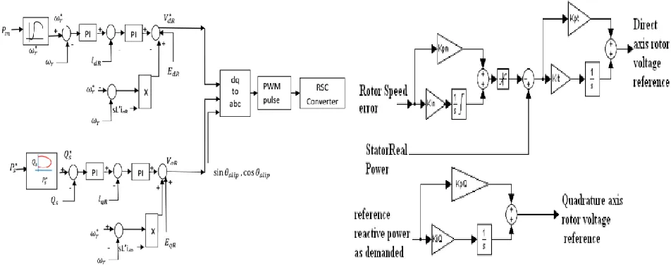
III. DFIGRSC AND GSCCONTROLLER DESIGN AND MODELING
The RSC control scheme is shown in Fig. 1b and GSC is shown in Fig. 1c. The RSC here is for extracting maximum power and controlling the reactive power from rotor side. Based on the wind speed, the optimal power that can be extracted can be estimated using lookup table. Using a well tuned PI controller, this optimal reference power is compared
with stator output power. The output from voltage based PI controller current and vice-versa. This 2nd PI controller output is compared with decoupled and disturbance parameter and finally rotor d-axis voltage is obtained. Similarly, from stator and grid reference real and reactive power, the RSC injecting reactive power can be estimated in the outer control loop of q-axis based RSC. The output divided and manipulated with voltage, we will get reference q-axis current. This reference current is measured with actual q-axis rotor current and the error is compared with PI controller to get reference q-axis rotor voltage. This voltage similarly added vectorial with decoupled and disturbing parameters as in d-axis control of RSC, we will get final RSC controlled q-axis voltage. These final obtained two axis reference rotor voltages are given to the PWM controller to get pulses for RSC. The lookup table relation between Ps and Qs can be built up using equation (10b). Here the stator voltage is considered unity without any grid disturbances. However, considering the Vs in the lookup table program is easy. The control of final two axis rotor voltage with PI control is done using the equations (12a) and (12b).
Fig. 1b RSC modelling for better power flow control (left) and its d-q axis voltage reference extraction
V
pwmi
dcV
pwmi
sc * sci
*dc
V
PI
1D
1
PI
2G
1G
1-D
dc
sC
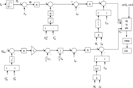
[image:5.612.69.545.485.674.2]Fig. 1c GSC modelling for DFIG with better power flow control from GSC to the grid The GSC based q-axis voltage is explained briefly here. The
grid voltage or stator voltage is generally required to maintain constant without fluctuations. This grid side voltage is maintained constant using rms based stator/ grid side voltage.
The reference value is
V
s*
1
in steady-state and is to bemaintained or compensated. As explained earlier, the error obtained from the reference to the actual voltages is given to the tuned PI controller to get the reference d-axis current. Now this reference current and the q-axis voltage reference are multiplied to get the reference power. The actual stator grid power values are obtained by direct measurement from the voltages and currents or using a wattmeter. The difference in the reference and actual grid power is another error and is divided with measured GSC q-axis voltage. Here we will get the reference current which is delivered by the GSC to the grid. The error produced because of the q-axis reference and actual q-axis currents are controlled with tuned PI and the output is q-axis GSC voltage. When this voltage is manipulated like in d-axis voltage, we get reference q-axis GSC voltage which is another input to inverse parks transformation to produce abc GSC reference voltage. This
reference voltage is given to the GSC based PWM for the pulse generation and to the GSC converter.
IV. SIMULATION RESULTS AND ITS ANALYSIS
Time in seconds
R
e
a
ct
iv
e
p
o
w
e
r
in
v
a
r
R
e
a
l p
o
w
e
r
in
w
a
tt
s
T
o
rq
u
e
in
N
m
S
p
e
e
d
in
R
P
M
Time in seconds
R
e
a
ct
iv
e
p
o
w
e
r
in
v
a
r
R
e
a
l p
o
w
e
r
in
w
a
tt
s
T
o
rq
u
e
in
N
m
S
p
e
e
d
in
R
P
[image:7.612.70.535.60.403.2]M
Fig. 2a DFIG parameters using (A) conventional [23] and proposed methods at randomly varying wind speed, Fig. 2a (B) zoom representation of the same figure as in (A)
The simulation analysis is to test how fast and accurate the DFIG system when source side issues like change in wind speed occur. The turbine rotor blades are set to run the generator at 2500rpm with flexibility in blade adjustment. The results are presented in Fig. 9a and 9b are comparison using conventional [23] and proposed RPIFOC technique. Here generator- turbine set is connected to the grid using a common bus-bar. In this case, the wind speed is fluctuating in nature with a mean of 3m/s with 14m/s as base speed. In Fig.2a(A), from top to bottom, the rotor speed in RPM, electromagnetic torque, stator real and reactive powers, which compares the conventional method (blue) described in [23] and to the one
proposed RPIFOC (red) in this paper. The same results in Fig. 2a(B), shows the zoom values of the same waveforms as in 3a(A).
It is seen that the rotor speed reached steady state earlier with proposed method than with conventional method. However in the zoom value of the speed which is having few distortions in the speed waveform with conventional (blue) than with proposed. Similarly, the torque settling with conventional for reference value of mechanical torque is earlier with proposed than with conventional. The zoom picture of same torque with conventional system has more ripples and surges than with proposed system.
The real and reactive powers with conventional and proposed are also shown in the figure. The powers with proposed has more instantaneous surge than with conventional system, but settles earlier than conventional with lesser ripples. Here the lesser ripples indicate smoother output power delivered from the DFIG system to the grid. The output power has wave shape like the wind speed waveform for both comparative systems, but smooth power delivery without ripples and surges
in the proposed RPIFOC technique. The change in reactive power with rotor speed is better with proposed technique.
Time in seconds
R
ot
or
q
a
xi
s
cu
rr
en
t
R
ot
or
d
a
xi
s
cu
rr
en
t
S
ta
to
r
q
ax
is
cu
rr
en
t
S
ta
to
r
d
ax
is
cu
rr
en
t
Time in seconds
R
ot
or
q
a
xi
s
cu
rr
en
t
R
ot
or
d
a
xi
s
cu
rr
en
t
S
ta
to
r
q
ax
is
cu
rr
en
t
S
ta
to
r
d
ax
is
cu
rr
en
[image:8.612.71.539.83.442.2]t
Fig. 3a DFIG currents using (A) using (A) conventional [23] and proposed methods at randomly varying wind speed, Fig. 3a (B) zoom representation of the same figure as in (A)
With the change in wind speed, the rotor speed is also changing in both conventional and proposed methods. It is observed that, the q-axis and d-axis stator and rotor currents are nearly constant, whereas the d-axis and q-axis stator and rotor currents are varying when wind speed is changing using conventional method [24, 25 and 26]. However, all the stator and rotor d and q axis currents are changing with change in wind speed or rotor speed given by the equations (stator currents 6a, 6b, 19a, 19b and rotor currents by 11, 17 and 18). It is based on the proposed control technique adopted with faster and accurate internal control scheme. In this method proposed, the stator and rotor flux interactions are made faster with the dynamics of generator and turbine operation. The external and internal control loops are sophisticated with quick control action described in section 2.1. The mechanical power output from turbine is almost same with both methods. Hence proposed method is faster and accurate with very less ripples in rotor speed, electromagnetic torque and DFIG currents.
V. CONCLUSION
The proposed reference power based improved field oriented control (RPIFOC) scheme is applicable for both low and high wind speed variations. It is also designed and developed for the extraction of maximum real power from the DFIG even near the cut-in wind speed of the turbine. During the light load conditions also, the maximum power extraction is possible with the proposed technique. The mechanical optimal power extraction is achieved using the tip-speed ratio method. In this method, the DFIG electromagnetic torque is controlled effectively at cut-in and nominal wind speed. The rotor speed is adjusted to an optimal value with the help of look-up table proposed in the RSC control scheme based on the generated torque and the rotor winding current. This rotor speed adjustment helps in effective control of reactive power in the rotor windings, maximum electromagnetic torque operation and also helps in mitigating
speed input to the turbine. Therefore the maximum real power flow from the stator and rotor is extracted from the turbine-generator set and near the unity power factor operation under the steady-state is possible. When the wind speed high, the mechanical power input to the turbine will be higher. The speed between 15 to 27m/s is said to be a good wind speed, where the output power from the turbine is almost constant. But, fluctuations in this speed to the above or below speeds make the power from the DFIG to fluctuate.
With the proposed scheme, the maximum output power can be extracted if rotor is made to drive at an optimal speed so that efficient pitch angle control and quicker operation is possible. Using the lookup table based technique, based on reactive power flow and turbine disturbances, the rotor speed and the reference powers are adjusted automatically under varying wind speed, the power fluctuations in the DFIG can be compensated. Hence, with all the above discussions, there is an improvement in the reactive power flow in the DFIG WECS so that the reference and actual powers are matching each other very smoothly. There are no surges or spikes in the waveforms of generator or turbine as smooth control of power flow and speeds are possible. In the same way, the rotor generator speed change for sub- synchronous or super-synchronous mode of speed is smooth, very quick and stable and also observed that there are no rotor or grid current surges during the dynamics. The comparison with wind speed variation case with previous works, the proposed system is better. Hence, with the proposed control scheme all source and grid side issues can be addressed easily without any change in the control strategy. The proposed IFOC technique ensures the wind turbine will follow maximum power operation point effectively than with a conventional MPPT-curve method. Also, the power fluctuations are minimized and surge currents are reduced using the proposed technique.
Compared to the conventional FOC, the proposed FOC is having lesser ripples and surges under steady ate and also when there is rapid change in the wind speed. The current, real and reactive power ripples are reduced, torque oscillations are lowered. The change in reference reactive power is met effectively with the proposed control scheme. The changes in the rotor speed with wind speed are smooth. The future scope for the present work is application for fault analysis and other types of grid disturbances.
Appendix
The parameters of each DFIG used in simulation are,
Rated stator Voltage = 690V, base power=20KW, Rated Power = 10units equivalents of 2KW=(10*2KW), Rs = 0.0049pu, Lls = 0.093pu, Lm = 3.39 pu, Rrӏ = 0.0049pu, Llr1 = 0.1pu, Inertia constant = 4.54pu, DC link Voltage = 1215V, DC link capacitance = 2000µF, Number of poles = 4, Grid voltage and frequency = 25KV and 60 Hz, Rotor side filter: Rfr and Lfr = = 0.3mΩ and 0.6nH, Grid side Filter: Rfg = 0.3Ω, Lfg = 0.6nH, nominal wind speed = 12 m/sec.
REFERENCES
1. Hossain, Md Emrad. "Improvement of transient stability of DFIG based wind generator by using of resistive solid state fault current limiter." Ain Shams Engineering Journal (2017), article in press.
2. Pradhan, Chittaranjan, Chandrashekhar Narayan Bhende, and Anik Kumar Samanta. "Adaptive virtual inertia-based frequency regulation in wind power systems." Renewable Energy 115, no. C (2018): 558-574. 3. Li, Shenghu, Wei Zhang, and Zhengfeng Wang, "Improved dynamic
power flow model with DFIGs participating in frequency regulation." International Transactions on Electrical Energy Systems, 27, no. 12 (2017).
4. P.K. Gayen, D. Chatterjee, S.K. Goswami, Stator side active and reactive power control with improved rotor position and speed estimator of a grid connected DFIG (doubly-fed induction generator), In Energy, Volume 89, 2015, Pages 461-472.
5. V.N. Ananth Duggirala, V. Nagesh Kumar Gundavarapu, Improved LVRT for grid connected DFIG using enhanced field oriented control technique with super capacitor as external energy storage system, In Engineering Science and Technology, an International Journal, Volume 19, Issue 4, 2016, Pages 1742-1752.
6. S. Mondal and D. Kastha, "Maximum Active and Reactive Power Capability of a Matrix Converter-Fed DFIG-Based Wind Energy Conversion System," in IEEE Journal of Emerging and Selected Topics in Power Electronics, vol. 5, no. 3, pp. 1322-1333, Sept. 2017..
7. Asit Mohanty, Meera Viswavandya, Prakash K. Ray, Sandipan Patra, Stability analysis and reactive power compensation issue in a microgrid with a DFIG based WECS, In International Journal of Electrical Power & Energy Systems, Volume 62, 2014, Pages 753-762.
8. J. Tian, D. Zhou, C. Su, Z. Chen and F. Blaabjerg, "Reactive Power Dispatch Method in Wind Farms to Improve the Lifetime of Power Converter Considering Wake Effect," in IEEE Transactions on Sustainable Energy, vol. 8, no. 2, pp. 477-487, April 2017.
9. G. Calderon Zavala, J. D. Mina Antonio, J. C. Rosas Caro, M. Madrigal Martinez, A. Claudio Sanchez and A. R. Lopez Nunez, "Simulation and Comparative Analysis of DFIG-based WECS Using Stator Voltage and Stator Flux Reference Frames," in IEEE Latin America Transactions, vol. 15, no. 6, pp. 1052-1059, June 2017.
10.Lin, W., Hong, C.: ‘A new elman neural network-based control algorithm for adjustable-pitch variable-speed wind-energy conversion systems’, IEEE Trans. Power Electron., 2011, 26, (2), pp. 473–481.
11.Kazmi SM, Goto H, Guo HJ, Ichinokura O. “A novel algorithm for fast and efficient speed-sensorless maximum power point tracking in wind energy conversion systems”, IEEE Trans. Ind. Elec. 2011 Jan; 58(1):29-36.
12.Y. Ju, F. Ge, W. Wu, Y. Lin and J. Wang, "Three-Phase Steady-State Model of Doubly Fed Induction Generator Considering Various Rotor Speeds," in IEEE Access, vol. 4, pp. 9479-9488, 2016.
13.Rahimi, Mohsen. "Improvement of energy conversion efficiency and damping of wind turbine response in grid connected DFIG based wind turbines." International Journal of Electrical Power & Energy Systems 95 (2018): 11-25.
14.Rahimi, Mohsen. "Coordinated control of rotor and grid sides converters in DFIG based wind turbines for providing optimal reactive power support and voltage regulation." Sustainable Energy Technologies and Assessments 20 (2017): 47-57.
15.Gayen, P. K., D. Chatterjee, and S. K. Goswami. "Stator side active and reactive power control with improved rotor position and speed estimator of a grid connected DFIG (doubly-fed induction generator)." Energy 89 (2015): 461-472.
16.Sarrias‐Mena, Raúl, Luis M. Fernández‐Ramírez, Carlos Andrés García‐Vázquez, and Francisco Jurado. "Dynamic evaluation of two configurations for a hybrid DFIG‐based wind turbine integrating battery energy storage system." Wind Energy 18, no. 9 (2015): 1561-1577. 17. Kaloi, Ghulam Sarwar, Jie Wang, and Mazhar Hussain Baloch. "Active
and reactive power control of the doubly fed induction generator based on wind energy conversion system." Energy Reports 2 (2016): 194-200. 18.Pande, V. N., Mate, U. M., & Kurode, S. (2013). Discrete sliding mode
19. Musau Moses, M., Abungu Odero, N., & Mwangi Mbuthia, J. (2012). Reducing Real and Reactive Power Losses in the Power Distribution System by DFIG Placement and Sizing Using Ordinary PSO and HGAPSO :A Comparison. International Journal of Emerging Technology and Advanced Engineering, 2.11 (2012).
20. Tanvir, A. A., Merabet, A., & Beguenane, R. (2015). Real-time control of active and reactive power for doubly fed induction generator (DFIG)-based wind energy conversion system. Energies, 8(9), 10389–10408. 21. Meegahapola, Lasantha, Brendan Fox, Tim Littler, and Damian Flynn.
"Multi‐objective reactive power support from wind farms for network performance enhancement." International Transactions on Electrical Energy Systems 23, no. 1 (2013): 135-150.
22. Vijayakumar, K., Kumaresan, N., Gounden, N. G. A., & Tennakoon, S. B. (2013). Real and reactive power control of hybrid excited wind-driven grid-connected doubly fed induction generators. IET Power Electronics,
6(6).
23. Gaillard, Arnaud, Philippe Poure, and Sharokh Saadate. "Reactive power compensation and active filtering capability of WECS with DFIG without any over‐rating." Wind Energy 13, no. 7 (2010): 603-614.
24. Patnaik, R. K., P. K. Dash, and Kaveri Mahapatra. "Adaptive terminal sliding mode power control of DFIG based wind energy conversion system for stability enhancement." International Transactions on Electrical Energy Systems 26, no. 4 (2016): 750-782.
AUTHORS PROFILE
D.V.N. Ananth was born in Visakhapatnam, India on 20th August 1984. He received B.Tech Electrical Engineering from Raghu Engineering College, Visakhapatnam, and M.Tech from Sreenidhi Institute of Science &Technology, Hyderabad, India and Ph.D. from GITAM University in June 2018.. He is working as an Assistant Professor in RAGHU Institute of Technology, in Electrical Department. His favorite topics include Renewable energy resources, DFIG, industrial drives, power systems, power electronics, control systems, HVDC and Reactive power compensation techniques. His contact address is [email protected].
![Fig. 2a DFIG parameters using (A) conventional [23] and proposed methods at randomly varying wind speed, Fig](https://thumb-us.123doks.com/thumbv2/123dok_us/8214726.263926/7.612.70.535.60.403/dfig-parameters-using-conventional-proposed-methods-randomly-varying.webp)
![Fig. 3a DFIG currents using (A) using (A) conventional [23] and proposed methods at randomly varying wind speed, Fig](https://thumb-us.123doks.com/thumbv2/123dok_us/8214726.263926/8.612.71.539.83.442/dfig-currents-using-conventional-proposed-methods-randomly-varying.webp)
