XXX-X-XXXX-XXXX-X/XX/$XX.00 ©20XX IEEE
Optimization and comparison of flux-concentrating
Nd-Fe-B generator considering variable power factor
and wind conditions for a 6MW offshore wind turbine
Nurul Azim Bhuiyan Alasdair McDonald University of Strathclyde, UK University of Strathclyde, UK [email protected], [email protected]
Abstract—A large proportion of offshore wind turbine designs are now based on directly driven permanent magnet synchronous generators using rare earth materials. During last few years, the price of Nd-Fe-B has increased and fluctuated significantly. The large price fluctuations encourage us to look at flux-concentrating Nd-Fe-B generator (where flux-concentrating characteristics helps to increase flux density in the air gap) and optimize that for offshore wind turbine generator.In this paper, a 6 MW generator using Nd-Fe-B magnet is designed analytically in MATLAB, where magnets are placed between magnetically conducting pole shoes to reinforce the air gap flux. The generator design is optimized for the best performance machine and lowest cost of energy. Further optimization is performed to compare the results with a 6 MW surface-mounted Nd-Fe-B generator. It is found that, the flux-concentrating Nd-Fe-B generator gives better cost of energy compare to surface mounted Nd-Fe-B generator. The effect of variable power factor and sensitivity to wind conditions are also estimated in this study.
Keywords—Cost of energy, flux-concentrating Nd-Fe-B generator, optimization, variable power factor, wind condition, wind turbine
I. INTRODUCTION
Permanent magnet synchronous generator (PMSG) has received much attention in wind energy operation because of their property of self-excitation (no need of field winding and unreliable slip ring and brush), which allows an operation at a high power factor, efficiency, stability and reliability. A direct driven PMSG which can be connected with gearless, multiple numbers of poles to generate power at lower rotational speed, is also very attractive due to lower weight and better wind energy utilization [1], [2]. Some of the weakness of these generators include their large size (due to the high torque rating), requirements for large quantities of rare earth permanent magnets and the significant generator structures [3].
The most common material used in permanent magnet electrical machines is Neodymium - Iron - Boron (Nd-Fe-B). This type of material has a high maximum energy product (BHmax = 30-50MGOe) that helps to compact machines with light generator rotors.During last few years, the price of Nd-Fe-B has increased and fluctuated significantly.Export quotas are subject to strategic decisions, demand is high and growing and raw materials are subject to speculation [4]. The cost uncertainty encourages designers to look for alternative generator topologies to reduce the use of rare earth permanent magnet materials. A generator with flux-concentrating ferrite
magnet in rotor can be competitive to the rare earth neodymium magnet for wind turbine application in terms of cost of energy, power production and high temperature if the masses of ferrite magnets are not a big issue [5], [13]. This study examines the performance of a flux-concentrating Nd-Fe-B (FC Nd-Nd-Fe-B) generator where flux density in the air gap increase due to its flux-concentrating nature and compare with a surface-mounted Nd-Fe-B (SM Nd-Fe-B) generator to estimate the difference in terms of cost of energy, annual energy production, losses, magnet use and other variables.
To achieve the best performance machine, the machine designer needs to employ some optimization with required objective function. Genetic Algorithms (GA) have been proved to be good and trustworthy methods of solving such problems. Although GAs are good at searching global optima over an entire problem region, the speed of convergence to the optimal point can be slow [6]. A hybrid algorithm combining Genetic and Pattern search (good for local search) can be used to solve this problem [5], [7].
The main purpose of this paper is to optimize a 6 MW FC Nd-Fe-B generator and compare with a 6 MW SM Nd-Fe-B generator for offshore wind energy operation assuming the generators run at unity power factor at all wind speeds. This paper also estimates the effect of variable power factor where the phase current is between the induced emf and terminal voltage. This paper further examines the effect of different wind condition on turbine cost of energy and annual energy production.
II. METHODOLOGY
In this section, the specification of the wind turbine for this study is defined – these lead to generators modelling, variable power factor and different wind conditions. The optimization process, independent variables, constraints, objective functions and post-processing comes after that.
A. Wind Turbine Specification
A three bladed, pitch regulated variable speed wind turbine is used in this study for 6 MW offshore operation. Table I gives the key ratings and assumptions for this study. For the simplification of the analysis, it is assumed that, the turbine rotor operates at maximum coefficient of performance below the rated wind speed and at wind speeds above the rated, the blades are immediately pitched and power output is limited to 6MW. The turbine is placed at an offshore site with a mean wind speed of 9.6m/s, as defined using a Weibull distribution defined by the data in Table I.
TABLEI
SPECIFICATION OF THE WIND TURBINE AND SITE WIND RESOURCES [5]
Rated grid power (MW) 6
Rotor diameter (m) 145
Rated wind speed (m/s) 11
Cut in wind speed (m/s) 3
Cut out wind speed (m/s) 25
Rated rotational speed (rpm) 12
Optimal tip speed ratio 8.3
Coefficient of performance at optimal tip speed ratio 0.48 Wind turbine availability (%) [8] 94 Turbine capital cost (exc. generator and foundation) (k€) 17530 Site wind speed shape parameter 2.3 Site wind speed scale parameter (m/s) 10.8
Mean wind speed (m/s) 9.6
B. Generator Modelling
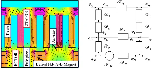
The generators are modelled analytically in MATLAB. The magnetic properties of the chosen Nd-Fe-B magnet is given in [9]. Lumped parameter magnetic circuit models are used to calculate flux per pole. Simplified (linearized) sections of the FC Nd-Fe-B generator with magnetic field and magnetic circuit models for one pole pair are shown in Fig. 1. This is verified using finite element software [10]. The results from this magnetic circuit are used to calculate the flux density in the various parts of the system and the induced emf as shown in [11].
F M
R g R g
φg
R M R sy
φg
φsy
φsy φsy
φM
φM φM
R t R t
R p R p
φL φL φL
R L
φL
Pole pie
ce
Buried Nd-Fe-B Magnet
Air
-gap
ROT
OR
ST
A
T
OR
T
[image:2.612.351.544.155.246.2]ooth
Fig. 1. (a) Magnetostatic finite element analysis of FC Nd-Fe-B generator, (b) Magnetic circuit. 0T→1.5T. Software is FEMM [10]
The phasor diagram of a flux-concentrating generator and a SM Nd-Fe-B generator with unity power factor is given in Fig. 2 and Fig. 3. The electrical equivalent circuit modeling, masses of different materials and costs calculation are the same as the method in [5] and [11]. The assumed costs in Table II for different materials are taken from [5] and [12]. Generator structural modelling, tower and foundation calculation given in [5] is also used in this study.
Fig. 2. Phasor diagram of a flux-concentrating machine with unity power factor
where Xd, Xq, Id and Iq represents the direct axis and quadrature axis reactance and current respectively.
Fig. 3. Phasor diagram of a surface-mounted machine with unity power factor
TABLEII
GENERATOR MATERIALS AND COST MODELING [1],[6]
Generator Material Characteristics
Slot filling factor 0.6
Resistivity of copper at 120oC (µΩ·m) 0.024
Eddy-current losses in laminations at 1.5 T, 50 Hz (W/kg) 0.5 Hysteresis losses in laminations at 1.5 T, 50 Hz (W/kg) 2
Cost Modeling
Lamination cost (€/kg) 3
Copper cost (€/kg) 15
Permanent magnet cost (€/kg) 60
Rotor iron cost (€/kg) 2
Aluminum cost (€/kg) 10
Structural steel cost (€/kg) 2
Price of kWh energy (€/kWh) 0.19
θ
I
V
E
jIX
δ
IR
[image:2.612.46.294.555.669.2]Fig. 4 shows the phasor diagram of a SM Nd-Fe-B generator with variable power factor (in this study it is leading power factor, where the angle between terminal voltage and current, θ is always half of the load angle, δ).
The terminal voltage can be found as,
(1)
where E is the induced emf, I is the current, X is the reactance and R is the resistance. Load angle can be calculated as,
(2) The electrical power output can be calculated as,
(3) The other electromagnetic, structural, tower and foundation calculations are same as SM Nd-Fe-B generator.
C. Different Wind Conditions
The sensitivity to wind conditions are performed by varying the wind speed scale parameter when the shape parameter is fixed. Again by varying mean wind speed when the other parameters are fixed. Both of the sensitivity analysis are performed to estimate the effect on cost of energy and annual energy production.
D. Optimization
Optimization process is performed by using hybrid Genetic and Pattern search algorithm in MATLAB. A detailed optimization process with flow chart is shown in [5]. The boundary limits, lower boundaries (LB) and the upper boundaries (UB) of independent variables for three types of generator are given in Table III. The boundary limit for the SM Nd-Fe-B generator is more flexible in this study compare to [5], to allow the maximum air gap diameter.
TABLEIII
BOUNDARY LIMITS FOR INDEPENDENT VARIABLES Independent Variables
FC Nd-Fe-B SM Nd-Fe-B SM Nd-Fe-B (θ = 0.5δ) LB UB LB UB LB UB Air gap diameter, D (m) 6 15 6 15 6 15 Axial length, ls (m) 0.7 1.8 0.7 1.8 0.7 1.8
Magnet width/pole pitch, wm/τp 0.5 0.9 0.5 0.9 0.5 0.9
Magnet height, hm (m) 0.01 0.08 0.01 0.06 0.01 0.06
Pole pairs, p (-) 60 100 60 100 60 100 Height of tooth, ht (m) 0.04 0.09 0.04 0.09 0.04 0.09
A number of assumptions and constraints are used, such as setting the air gap clearance to a fixed ratio of the machine diameter, maximum flux density to avoid saturation in stator and rotor yoke and limiting rated electrical power to greater than or equal to 6 MW.
From the previous study in [5], it was found that the objective function for minimum cost of energy which includes electromagnetic and structural materials is one of the efficient way for the wind turbine designer to optimize. This study looks for only one objective function given as,
(4) where FCR is the fixed charge rate, ICC is the initial capital cost of the turbine (including the generator), AOM is the annual operation and maintenance (assumed to be unaffected by the generator design) and Ey, the annual energy production (AEP) of the turbine. During optimization, the variation of the independent variables leads to changes in capital cost and energy yield.
After the optimization process is complete, dependent variables such as efficiency, annual energy production, losses, flux density, cost and masses of different active and structural materials are produced.
E. Runs/Investigations
Initially, the optimization program was run for the FC B generator. After that, the optimization for the SM Nd-Fe-B generator was run with flexible boundary limit from [5]. The SM Nd-Fe-B generator then modified with variable power factor and the optimization program was run after that. Finally, a sensitivity analysis was performed on the wind conditions to estimate the effect on the cost of energy and the annual energy production for a 6 MW FC Nd-Fe-B generator.
III. RESULTS
A. Generator Topologies and Power Factor
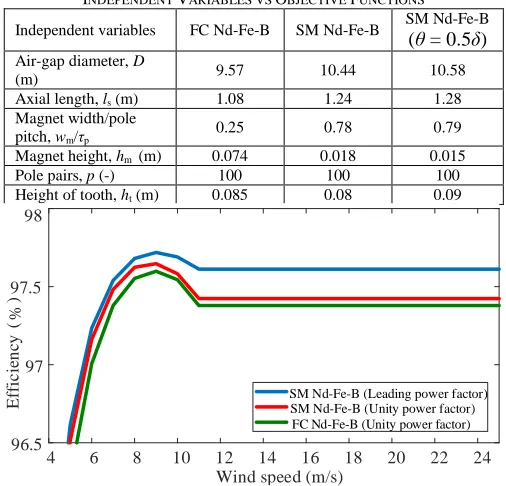
Table IV shows the independent variables selected by the optimization for different generators. Fig. 5 shows the efficiency curves for these different designs.
TABLEIV
INDEPENDENT VARIABLES VS OBJECTIVE FUNCTIONS
Independent variables FC Nd-Fe-B SM Nd-Fe-B SM Nd-Fe-B (θ = 0.5δ) Air-gap diameter, D
(m) 9.57 10.44 10.58
Axial length, ls (m) 1.08 1.24 1.28
Magnet width/pole
pitch, wm/τp 0.25 0.78 0.79
Magnet height, hm (m) 0.074 0.018 0.015
Pole pairs, p (-) 100 100 100
Height of tooth, ht (m) 0.085 0.08 0.09
4 6 8 10 12 14 16 18 20 22 24
Wind speed (m/s) 96.5
97 97.5 98
(%
)
SM Nd-Fe-B (Leading power factor) SM Nd-Fe-B (Unity power factor) FC Nd-Fe-B (Unity power factor)
E
ffi
c
ie
n
cy
[image:3.612.314.567.432.675.2]It is found that, the power factor at rated wind speed is 0.94 for the SM Nd-Fe-B generator with variable power factor after optimization, where the power factor varies with load angle at below rated wind speed.
All the three generator design give similar efficiency, where the efficiency of SM Nd-Fe-B with variable power factor is slightly higher (97.6%) than other generators.
Fig. 6 shows the post-processed optimization results for different dependent variables. Where SM Nd-Fe-B generator with variable power factor gives minimum cost of energy of €104.6/MWh in Fig. 6(a). Fig. 6(b) shows the annual energy production of different generator design, where SM Nd-Fe-B generator with variable power factor gives maximum energy of 30 GW. The FC Nd-fe-B generator gives minimum active material cost €520.5k, shown in Fig. 6(c). Fig. 6(d) shows the magnet mass of different generator designs, where SM Nd-Fe-B generator with variable power factor gives minimum magnet mass of 3.82 tonnes.
(a)
1 2 3
104 104.5 105 C o E ( €/ M W h ) (b)
1 2 3
29.8 29.9 30 A E P ( G W h ) (c)
1 2 3
Generator type 500 510 520 530 A c ti v e m at e ri al c o st (k €) (d)
1 2 3
[image:4.612.316.564.203.344.2]Generator type 3.5 4 4.5 M ag n et m as s (t o n n e )
Fig. 6. Post-processed optimization results for some dependent variables, where in x-axis, 1,2 and 3 represents different generator design, FC Nd-Fe-B, SM Nd-Fe-B and SM Nd-Fe-B with variable power factor respectively
TABLEV
POST-PROCESSED OPTIMIZATION RESULTS
Variables FC Nd-Fe-B SM Nd-Fe-B SM Nd-Fe-B (θ = 0.5δ) Air-gap flux density,
Bg (T) 1.03 0.78 0.78
Mass of magnet, mPM
(kg) 4479.8 4500.6 3820.2
Mass of copper, mCu
(kg) 9494.9 11063 12837
Mass of active iron,
mFe (kg) 34239 32489 33828
Structural mass, mstr
(kg) 25847 32238 29848
Copper losses (MWh) 582.1 587.7 547.8 Iron Losses (MWh) 269.5 246.3 236.4 Generator active
materials cost(k€) 520.5 531.6 523.3 Generator structural
materials cost(k€) 104.8 128.9 119.4 Converter cost (k€) 121.8 121.8 129.6
AEP (GWh) 29.92 29.94 29.99
Cost of energy
(€/MWh) 104.8 104.9 104.6
Table V shows the some of the post-processed results after optimization for different generator design.
B. Different Wind Conditions
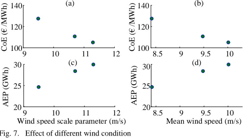
Fig. 7(a) and Fig. 7(c) shows the effect on cost of energy and annual energy production for the 6 MW FC Nd-Fe-B generator by varying the wind speed scale parameter from 9.5 m/s to 11.3 m/s with fixed shape parameter 2. Fig. 7(b) and Fig. 7(d) shows the effect on cost of energy and annual energy production for the 6 MW FC Nd-Fe-B generator by varying the mean wind speed from 8.4 m/s to 10 m/s. The SM Nd-Fe-B generator also gives the similar results when the wind speed scale parameter and the mean wind speed are varied.
9 10 11 12
100 120 140 (a) CoE ( € /M W h )
8.5 9 9.5 10
100 120
140 (b)
CoE ( € /M W h )
9 10 11 12
20 25
30 (c)
Wind speed scale parameter (m/s)
A E P ( G W h )
8.5 9 9.5 10
20 25
30 (d)
Mean wind speed (m/s)
A E P ( G W h )
Fig. 7. Effect of different wind condition
IV. DISCUSSIONS
A. On the Choice of Generator Topology and Variable Power Factor
The FC Nd-Fe-B and the SM Nd-Fe-B gives similar efficiency and SM Nd-Fe-B with variable power factor gives slightly better efficiency than others which effect on their cost of energy. The FC Nd-Fe-B generator gives slightly better cost of energy than the SM Nd-Fe-B generator due to its flux concentrating nature which needs less active materials cost and the SM Nd-Fe-B with variable power factor gives much better in comparison with other two generators due to its lower losses. The FC Nd-Fe-B generator use slightly less magnet than the SM Nd-Fe-B generator due to its flux concentrating nature which helps to increase air-gap flux density and the SM Nd-Fe-B generator with variable power factor needs a very less amount of magnet but the large amount of copper minimize the difference in generator mass in compare to other generators. The FC Nd-Fe-B always gives lowest structural mass with similar generator diameter of the SM Nd-Fe-B generator as the radial height of flux-concentrating poles is larger than that of a surface-mounted magnet, the rotor structure is slightly larger when using the surface-mounted Nd-Fe-B magnets.
[image:4.612.47.299.271.431.2]B. On the Sensitivity to Wind Conditions
By increasing the wind speed scale parameter while the shape parameter is constant, the cost of energy decreases and the annual energy production increase. Similarly, by increasing the mean wind speed the cost of energy decrease and the annual energy production increase. It is due to the probability of Weibull distribution increase by increasing wind speed scale parameter and mean wind speed which produce more energy and reduces the cost of energy.
V. CONCLUSIONS
A flux-concentrating Nd-Fe-B generator is designed and optimized for an objective function minimum cost of energy for offshore wind turbine application. It is compared with a surface mounted Nd-Fe-B generator with unity and variable power factor. It has been shown that, the FC Nd-Fe-B generator gives slightly better cost of energy than SM Nd-Fe-B when assuming unity power factor.
It has also been shown that, the machine with variable power factor where varying the load angle so that the phase current is between the induced emf and terminal voltage produces better annual energy and lower cost of energy than the machine with unity power factor.
The effect on turbine cost of energy and annual energy production due to different wind conditions have also been shown in this study.
REFERENCES
[1] T. F. Chan, and L. L. Lai., “Permanenet-magnet machines for distributed generation: a review,” Proc. IEEE power engineering annual meeting, Tampa, FL, USA, 2007,pp. 1-6.
[2] X. M. Li, Z. X. Yang, Y. B. Li, W. Chen, and L. P. Zhang, “Performance analysis of permanent magnet synchronous generators for
wind energy conversion system,” International Conference on Advanced Mechatronic Systems, Melbourne, Australia, 2016, pp. 544–549. [3] M. A. Mueller, A. S. McDonald, D. E. Macpherson, “Structural analysis
of low-speed axial-flux permanent-magnet machines,” IEE Proc. – Electr. Power Appl., vol. 152, no. 6, pp. 1417–1426, Nov. 2005. [4] C. Hurst, China’s Rare Earth Elements Industry: WhatCan the West
Learn?. Institute for the Analysis of Global Security(IAGS), Fort Leavenworth, KS. USA (2010) [Online]. Available at:
http://www.iags.org/rareearth0310hurst.pdf, Accessed on: Mar. 28, 2018. [5] A. McDonald and N. A. Bhuiyan, “On the Optimization of Generators
for Offshore Direct Drive Wind Turbines,” IEEE Trans. Energy Convers., vol. 32, no. 1, pp. 348-358, Mar. 2017.
[6] K. Choi, D. H. Jang, S. I. Kang, J. H. Lee, T. K. Chung and H. S. Kim, “Hybrid Algorithm Combing Genetic Algorithm With Evolution Strategy for Antenna Design,” IEEE Trans. Magn., vol. 52, no. 3, pp. 1-4, Mar. 2016.
[7] Y. Tai, Z. Liu, H. Yu, and J. Liu, “Efficiency optimization of induction motors using genetic algorithm and Hybrid Genetic Algorithm,” in Proc. Int. Conf. Elect. Mach. and Syst., Beijing, China, 2011, pp. 1-4. [8] J. Carroll, A. McDonald, I. Dinwoodie, D. McMillan, M. Revie, and I.
Lazakis, “Availability, operation and maintenance costs of offshore wind turbines with different drive train configurations,” Wind Energ.,Jul. 2016, [Online]. Available at: http//dx.doi.org/10.1002/we.2011. [9] N. A. Bhuiyan and A. McDonald, “Optimisation and comparison of
generators with different magnet materials for a 6MW offshore direct drive wind turbine,” in Proc. 8th IET Int. Conf. Power Electron., Mach. Drives, Glasgow, UK, 2016, pp. 1-6.
[10] Finite Element Method Magnetics v4.2. (2016) [Online] Available at: http://www.femm.info/wiki/HomePage
[11] N. A. Bhuiyan and A. McDonald, “Assessment of the Suitability of Ferrite Magnet Excited Synchronous Generators for Offshore Wind Turbines,” presented at Eur. Wind Energy Assoc. Offshore Conf., Copenhagen, Denmark, Mar. 10-12, 2015.
[12] H. Polinder, F. F. A. Van der Pijl, G. J. De Vilder, and P.J. Tavner, “Comparison of direct-drive and geared generator concepts for wind turbines," IEEE Trans. Energy Convers., vol. 21, no. 3, pp. 725-733, Sept. 2006.
[13] S. Eriksson, H. Bernhoff, “Rotor design for PM generators reflecting the unstable neodymium price,” in Proc. XXth Int. Conf. Elect. Mach.,