International Conference on Mechanical Engineering Research (ICMER2013), 1-3 July 2013 Bukit Gambang Resort City, Kuantan, Pahang, Malaysia Organized By Faculty of Mechanical Engineering, Universiti Malaysia Pahang Paper ID: P341
1
THE DEVELOPMENT OF MILD COMBUSTION OPEN BURNER EXPERIMENTAL SETUP
M.M.Noor1,2, Andrew P.Wandel1 and Talal Yusaf2,3
1
Computational Engineering and Science Research Centre, School of Mechanical and Electrical Engineering, University of Southern Queensland (USQ), Australia 2
Faculty of Mechanical Engineering, Universiti Malaysia Pahang (UMP), Malaysia 3
National Centre for Engineering in Agriculture, USQ, Australia
*
Email: [email protected] / [email protected]
ABSTRACT
This paper discusses the development of the combustion furnace for the Moderate and Intense Low oxygen Dilution (MILD) combustion. The development was started with using Computational Fluid Dynamics (CFD) software. ANSYS Fluent was used to simulate preliminary designs for the burner before the final design sent to workshop to build it. The requirement of MILD combustion are air fuel mixture preheat and dilute the oxygen content in the oxidant stream. In order to achieve this condition, Exhaust Gas Recirculation (EGR) was utilised. The burner requirement is in non-premixed and open burner. To capture and used the exhaust gas, the burner was enclosed with large circular shape wall with open at the top. External EGR pipe was used to transport the exhaust gas and mixed with the fresh oxidant (normal air or syntactic air). Butterfly valve was installed at the top opening as damper to close the exhaust gas flow at the certain ratio for EGR and exhaust out to atmosphere. This damper must be long enough to prevent from backflow of normal air into the combustion chamber. The R-type and K-type thermocouple wire was used to measure the temperature inside the combustion chamber and the EGR pipe. The lambda and gas sensor was installed to measure the gas compositions. Data acquisition system used to collect the temperature and gas compositions in combustion chamber, EGR pipe and exhaust gas. Three high temperature glass windows (fused silica) were installed to view and capture the image of the flame and analysed the flame propagation. The furnace development completed and ready to be tested.
Keywords: experimental setup, computational fluid dynamics, bluff-body MILD burner
INTRODUCTION
2
needs and pollution emission, the combustion researchers are focusing on the improvement of the combustion efficiency, new combustion technology and combustion modeling (Merci et al., 2007; Smith and Fox, 2007; Noor et al., 2012a).
MILD combustion is one of the new combustion technology that produce lower pollution emission and increase the thermal efficiency (Dally et al., 2002, 2010; Cavaliere and Joannon, 2004; Christo and Dally, 2004; Weber et al., 2005; Noor et al., 2012a). This combustion also called flameless oxidation or FLOX (Wünning, 1991, 1996, 2004, 2005; Wünning and Wünning, 1996, 1997; Milani and Wünning, 2007; Mancini et al., 2002, 2007), low NOx (Orsino et al., 2001) and high-temperature air combustion (HiTAC) (Katsuki and Hasegawa, 1998; Tsuji et al., 2003). MILD combustion has been investigated experimentally (Hardestry and Weinberg, 1974; Plessing et al., 1998; Lille et al., 2005; Cabra et al., 2005; Rafidi and Blasiak, 2006; Derudi et al., 2007; Derudi and Rota, 2011; Li et al., 2011a, 2011b) and numerically (Coelho and Peters, 2001; Park et al., 2003; Yang and Blasiak, 2005a, 2005b; Awosope et al., 2006; Zhenjun et al., 2010; Parente et al., 2011; Szegö et al., 2011; Noor et al., 2012d) in various industrial applications. The main requirement for MILD combustion is oxygen dilution in the oxidant stream and temperature mixture temperature is above the self-ignition for the fuel. The oxygen dilution and the heating of the oxidiser can be achieved by the used of exhaust gas recirculation (EGR) (Katsuki and Hasegawa, 1998; Noor et al., 2012b; Yusaf et al., 2013). The hot EGR will dilute the oxygen in the oxidant and preheat it. The oxygen content in the fresh air will reduce depending on the ratio of the fresh air and EGR.
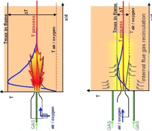
[image:2.595.174.426.485.701.2]The comparison of the flame temperature for the conventional and MILD combustion is shown in Figure 1. The different between minimum and maximum temperature (ΔT) for the conventional combustion is high compare to MILD combustion. The temperature distribution was more homogenous and this characteristic will give advantage to MILD combustion for many applications that need stable and distributed temperature throughout the combustion chamber.
Figure 1. Comparison for conventional and MILD combustion (Wünning, 2003)
3
14.5. Then the burner was built at USQ mechanical workshop. The testing and experimental work will be using methane, biogas and coal seam gas (CSG).
COMBUSTIONEQUATION
In order to design the combustion chamber, the basics of combustion equation must be used to calculate the air fuel ratio (AFR). The study of AFR using computational fluid dynamics (CFD) commercial package (ANSYS Fluent) was done to design the air and fuel inlet diameters and volume flow rates (Noor et al., 2012b). The balance combustion process will not produce unburned hydrocarbon (UHC) in the exhaust gas. That shows the combustion process consume all the fuels. The combustion process can be written in general hydrocarbon stoichiometric combustion equation:
( ) ( ) ( ) (1)
Stoichiometric combustion equation without EGR for low calorific value gas consists of 50% methane, 20% hydrogen and 30% carbon dioxide by volume (Noor et al., 2012c).
( ) ( )
( ) (2)
In more general form, the combustion equation without EGR is
( ) ( )( )
( ) ( ) (3)
For lean combustion, take equivalent ratio, ϕ = 0.5 and fuel composition are i = 0.5, j = 0.2 and k = 0.3,
( ) ( )
(4)
For rich combustion, take equivalent ratio, ϕ = 1.5 and fuel composition are i = 0.5, j = 0.2 and k = 0.3,
( ) ( )
(5)
and the combustion equation with EGR is
( ) ( )( )
( ) ( ) ( )
( ) ( ) ( ) ( ) ] (6)
where i, j and k is the mole fraction of the methane, hydrogen and carbon dioxide respectively and λ is the EGR ratio. The stoichiometric combustion equation for low calorific value gas consists of 50% methane, 20% hydrogen and 30% carbon dioxide by volume, half of flue gas will flow back to the chamber and lower the oxygen level in the oxidizer stream. An example, for this composition at stoichiometric condition, ϕ is 1.0, and 75% EGR, the balance equation is
4
( ) ( ) (7)
For lean combustion, the excess oxygen and nitrogen will not be involved in combustion and exhaust through the flue gas. These excess can be seen in an example (Equation 8) of ϕ is 0.5, and 33% EGR, the balance equation is
( ) ( )
(8)
In the rich combustion process, due to not enough oxygen to burn high mass fraction of CH4, excess methane and hydrogen will not be involved in combustion and becoming unburned hydrocarbons. These conditions can be seen in an example (Equation 9) of ϕ is 1.5, and 66% EGR, the balance equation is
( ) ( )
(9)
If the fuel is biogas with only methane and carbon dioxide, the general form of the combustion equation with EGR is
( ) ( ) ( )
( ) ( ) ] (10)
COMPUTATIONAL FLUID DYNAMICS
CFD is an important design tool that has been extensively used to explore and design the engineering hardware (Baukal et al., 2001; Davidson, 2002, Noor et al., 2012a; Najiha et al., 2012a, 2012b) including combustion chambers. CFD was increasingly being used for the optimisation of gas burner (Scharler and Obernberger, 2000) and industrial gas furnace (Dally et al., 2004; Riahi et al., 2012; Noor et al., 2013) or coal combustion (Calchetti et al., 2007). In this study, the CFD package ANSYS FLUENT 13.0, 14.0 and 14.5 was used to model MILD combustion in the mode of non-premixed combustion.
A governing equations used including mass, momentum, energy and species in addition to the turbulence transport and combustion model were discretized in the whole domain using the second-order schemes. The realizable k−ε turbulence model (Shih et al., 1995) [that developed based on standard k-ε turbulence model (Launder and Spalding, 1974)] was used for turbulence model (Peters, 2000; Pope, 2000) and discrete ordinate (DO) model (Chui and Raithby, 1993) for radiation model. DO model is applicable to a wide range of optical thicknesses. The optical thickness for MILD combustion flames is not well defined makes DO model a good selection for the radiation model. This model solves a radiative transfer equation. Weighted sum of gray gas model (WSGGM) was used for the absorption coefficient which was conceptually developed in 1967 (Hottel and Sarofim, 1967) and used for spray combustion (Choi and Baek, 1996) and gas furnace (Liu et al., 1998). The WSGGM is having reasonable compromise between the oversimplified gray gas model and a complete model.
5
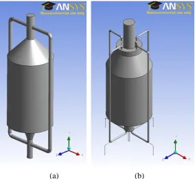
EGR pipe (Figure 2) to transport the exhaust gas to mix it with fresh air. Those 2 models was not success to ensure the exhaust gas get into the EGR pipe and flow down. For the early design (Figure 2(a)), this is due to the EGR in the inlet of EGR at the top is not helping the fluid flow. The 90o inlet angle was not letting the exhaust gas flow into the EGR pipe as plan.
The design for the EGR inlet was change (Figure 2(b)) with the inlet is direct in the vertical direction. This is in line with the flame and exhaust gas direction and easy for the exhaust gas to flow into the EGR pipe. The outlet for the exhaust move downward to make the inlet for EGR is bigger and can be seen in Figure 2(b) and 3(a). The small EGR pipe (Figure 2(b)) only allows small volume of exhaust gas flow downward. In order to increase the volume of exhaust gas flow, the EGR pipe increase from 25 mm to 50 mm diameter (Figure 3(b)). The same principle as EGR pipe inlet, the EGR pipe outlet also finally install at the side of each EGR to help the EGR flow (Figure 3(a) and 3(b)). This design also to ensure the exhaust gas mix properly before enter the combustion chamber. Nakamura et al. (1993) and Weber et al. (2000, 2001) experimentally studied pilot-scale furnaces equipped with heat exchangers and demonstrated that heat transfer was affected by the port locations and angles.
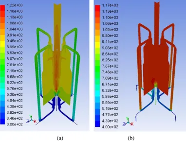
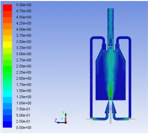
The simulation was done on the final model (Figure 3(b)) for the ignition location study (Noor et al., 2013), air fuel ratio study (Noor et al., 2012b) and other parametric study (Noor et al., 2012d, 2012e) on the MILD combustion using biogas as a fuel. Difference combination of air and fuel compositions injected to the chamber giving different result. When the oxygen level is from 3 to 13% before mixed with fuel, then MILD combustion will be achieved (Figure 4(b)). Otherwise the combustion is not achieved MILD state (Figure 4(a)). Figure 5 shows the velocity magnitude of the flow in the chamber. This flow shows that the chamber is open and the pressure in the chamber is at atmospheric pressure since the chamber is open on the top. This open chamber is considered as open MILD combustion furnace.
[image:5.595.156.441.470.731.2]
(a) (b)
6
[image:6.595.148.457.111.381.2](a) (b)
Figure 3: Final design with bigger EGR pipe (a) 2D schematic diagram (b) 3D image
(a) (b)
[image:6.595.114.497.437.727.2]7
Figure 5: Velocity magnitude
MODEL DEVELOPMENT
The development of the burner was done at USQ mechanical workshop. The schematic diagram for the overall gas system and burner is shown in Appendix A. There are consisting of 3 main parts which are gas system, burner and data acquisition. The gas system is including 5 gas cylinder, gas supply line and valve and gas control panel. The gas control panel was the place where the gas will be mixed and the flow rate will be controlled. The burner system including burner, ignition system and EGR pipe are shown in Figure 6. The data acquisition system will be discussed in the next section.
The ignition process was designed using spark ignition in the recirculation zone (Noor et al., 2013). A study on recirculation zone for the ignition location was done using CFD. Figure 7(a) shows the flame flow field with Figure 7(b) as the mixing recirculation zone. Figure 7(b) shows that there are two types of recirculation zone: the inner recirculation zone (IRZ) formed in between the air and fuel jet flow of bluff-body and the outer recirculation zone (ORZ) formed outside the annulus air flow. The recirculation of the mixture of fuel and air was important due to that process will create the turbulent flow of the mixture which will enhance the mixing process. Mastorakos (2009), Triantafyllidis et al. (2009), Neophytou et al. (2012) and Noor et al. (2013) concluded that the best location for ignition was in the centre of inner recirculation zone where the recirculation velocity is almost zero.
8
[image:8.595.95.503.83.318.2]
(a) (b) (c)
Figure 6. MILD burner setup (a) burner (b) high temperature glass window (c) external safety covers for the burner
(a) (b)
[image:8.595.128.469.380.734.2]9
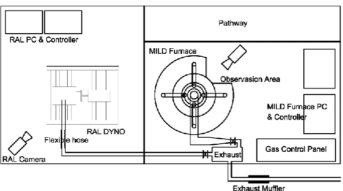
The furnace was installed in the USQ combustion laboratory (building called P7). The furnace shares the room with remote access laboratory (RAL) engine for the remote access experiment. The room layout was shown in Figure 10. The layout for MILD combustion system burner consist of the burner, exhaust system, data acquisition system equip with one computer and gas control panel. The data acquisition system will be discussed later in this paper. The gas control panel is for the gas supply to control the gas flow rate and mixing of gas. The gas supplies are methane, hydrogen, carbon dioxide, oxygen and nitrogen. Methane and carbon dioxide was use to mix and create biogas with the composition of 60% methane and 40% carbon dioxide. More study can be done with the effect of hydrogen mix with methane and carbon dioxide as a fuel. Oxygen and nitrogen is used to create the synthetics air supply with 5% to 30% of oxygen level in the mixing.
[image:9.595.119.475.267.552.2]
Figure 8. Schematic diagrams of combustion chamber, (a) ignition rod location, (b) location plan view and (c) location side view of ignition location and installation
(a) (b)
[image:9.595.122.475.600.743.2]10
Figure 10. MILD layout for the installation (plan view)
FURNACE POWER CALCULATION
The furnace power or heat release rate in unit Watt (W) can be calculate by mass flow rate (kg/s) times gas heating value (kJ/kg). The dimensional analysis is
W = Nm/s = kg/s x m2/s2 = kg/s x kJ/kg
= mass flow rate x gas heating value
Methane gas was injected through 10 mm inlet diameter. The area of the fuel inlet is 7.85 x 10⁻⁵ m2. The gas injected to the combustion chamber at the maximum rate of 25.0 litre/min. This is equal to 4.16 x 10⁻⁴ m3/s. The fuel speed injected is 5.3 m/s. The mass flow rate is depending on the density of the fluid. The density of methane gas is 0.668 kg/m3 (at 293K and 101.325 kPa), thus the mass flow rate is
m = gas density x volume flow rate = 0.668 kg/m3 x (4.16 x 10-4 m3/s) = 2.78 x 10⁻⁴ kg/s
Heat release by the combustion of methane can be calculated as below. Methane heating value is 55.0 MJ/kg (Table 1).
q = mass flow rate x gas heating value = (2.78 x 10⁻⁴ kg/s) x 55.0 MJ/kg = 15.3 kW
11
Table 1. Fuel heating value to calculate furnace Watt power
Fuel Composition Molar mass Specific heat Density g/mol MJ/kg KJ/mol BTU/Ib kg/m3
Hydrogen H2 2.01 141.8 286 61100 0.0899
Methane CH4 16.04 55.5 890 23900 0.6680
Ethane C2H6 30.07 51.9 1560 22400 1.2640 Propane C3H8 44.09 50.3 2220 21700 1.8820
Natural gas - 18 50.0 900 21600 0.8000
Butane C4H10 58.12 49.5 2877 20900 2.4890 Octane C8H18 114.23 47.9 5470 20600 703.00 Decane C10H22 142.28 47.6 6773 20500 730.00 Gasoline CnH1.87n 100-110 47.3 5400 20400 719.70 Diesel CnH1.75n 170-200 44.4 4480 19300 832.00
Carbon C - 32.8 393.5 14100 2.2650
Coal - - 21 275 11000 828.75
Wood - - 15 300 6500 650.91
DATA ACQUISITION SYSTEM
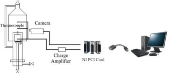
The instrumentation in USQ Combustion Laboratory was mainly equipped with a National Instrument (NI) data acquisition system and LabVIEW software. The temperature was measured on 32 different locations on various combustion chambers’ components such as the main chamber, air inlet, EGR pipe and exhaust pipe. The temperature was measured by R-type and K-type thermocouple which was connected to a 32-channel NI connector box. The thermocouple specification can be referred to Appendix B (Noor et al., 2012e). Figure 11 shows the arrangement of the data acquisition system of the test engine. The measurement was displayed in a LabVIEW graphical user interface (GUI) and can be recorded as an MS Excel format. Figure 12 shows the LabVIEW graphical user interface used to display and recorded the data. In this experiment, National Instruments Data Acquisition (NIDAQ) system was used to measure and display the temperature measurement through thermocouples. LabVIEW software was used to manage and store the data collected. It consists of chassis NIDAQ 9178 with a number of signal conditioning amplifiers and analogue to digital conversion modules.
12
[image:12.595.171.427.162.271.2]Gas analyser was used to measure the gas composition in the combustion chamber, EGR pipe and exhaust ducting. The analysis of gas composition is very important to evaluate the NOx emission, unburned hydrocarbon (UHC) and excess oxygen in the exhaust gas.
Figure 12. LabVIEW graphical user interface (GUI)
CONCLUSION
The design of the MILD combustion open furnace was successful with the use of ANSYS Fluent. The simulation of the MILD combustion was successful to achieve MILD state. The combustion has to be enclosed to collect the exhaust gas and utilised it to dilute the oxygen in the oxidant stream and at the same time, increase the oxidant temperature. Four EGR pipes were added to bring down the exhaust gas and mixed with the inlet air. The building and development of the furnace was carried out at University of Southern Queensland mechanical workshop. The furnace was equipped with three high temperature glass window to monitor and record the flame propagation. The R-type thermocouple was used for the main chamber temperature measurement since it can withstand up to 2040K. K-type thermocouple that can withstand up to 1645K was used to measure the temperature of the exhaust gas at the exhaust gas pipe on the top of the chamber and EGR pipe. Data acquisition system was used to collect and record the data from the thermocouples. The composition for the exhaust gas in the exhaust pipe and EGR pipe was measured using gas analysers. The furnace power calculated for the 25 litre/minute of methane is 15.3 kW.
ACKNOWLEDGMENTS
The authors would like to thank University of Southern Queensland (USQ), Ministry of Higher Education, Malaysia (MOHE) and Universiti Malaysia Pahang (UMP) for providing financial support and laboratory facilities. The first author also thanks to Abdul Aziz Hairuddin (UPM), Chris Galligan and Brian Aston (USQ Mechanical Workshop) and Dr. Paul Baker (USQ combustion laboratory) for comments and discussions.
REFERENCES
Awosope, IO., Kandamby, NH. and Lockwood, FC. 2006 Flameless oxidation modelling on application to gas turbine combustors, Journal of the Energy Institute, 79(2): 75-83.
13
British Petroleum, 2012 BP energy outlook 2030, British Petroleum PLC, January 2012, Cedigaz, Paris, France
Burley, NA., Powell, R.L., Burns, G.W. and Scroger, M.G. 1978 The Nicrosil vs Nisil thermocouple: properties and thermoelectric reference data. US Department of Commerce, Washington D.C., NIST Monograph 161, National Institute of Standards and Technology, US Department of Commerce, Washington DC, US. Burn, GW., Scroger, M.G., Strouse, G.E., Croarkin, M.C. and Guthrie W.E. 1993
Temperature-electromotive force reference functions and tables for the letter-designated thermocouple type based on the ITS-90. US Department of Commerce, Washington D.C., NIST Monograph 175, National Institute of Standards and Technology, US Department of Commerce, Washington DC, US.
Cabra, R., Chen, JY., Dibble, RW., Karpetis, AN. and Barlow, RS. 2005 Lifted methane–air jet flames in a vitiated coflow, Combustion and Flame, 143(4): 491-506.
Calchetti G, Nardo AD, Mongibello G and Mongiello C (2007), MILD combustion simulation of coal water slurry, Italian Section of the Combustion Institute 30th Meeting on Combustion, Ischia, Italy
Cavaliere A and Joannon MD 2004 MILD combustion, Prog Energy Comb Science, 30, 329-366
Choi CE and Baek SW 1996 Numerical analysis of spray combustion with nongray radiation using weight sum of gray gas models, Combust Sciences and Technology, 115, 297-315
Christo FC and Dally BB 2004 Application of transport PDF Approach for modelling MILD combustion, 15th Australasian Fluid Mechanics Conference, University of Sydney, Australia
Chui EH and Raithby GD 1993 Computation of Radiant heat transfer on a non-orthogonal mesh using the finite-volume method, Numerical Heat Transfer B, 23, 269-288, 1993
Coelho, PJ. and Peters, N. 2001 Numerical simulation of a MILD combustion burner, Combustion and Flame, 124: 503-518.
Dally BB., Karpetis A.N. and Barlow R.S. 2002 Structure of turbulent non-premixed jet flames in a diluted hot coflow, Proceeding of Combustion Institute, 29(1) 1147-1154
Dally, B.B., Shim, S.H., Craig, R.A., Ashman, P.J. and Szego, G.G. 2010. On the burning of sawdust in a MILD combustion furnace. Energy Fuels, 24: 3462-3470. Dally, BB, Riesmeier, E. and Peters, N. 2004 Effect of fuel mixture on moderate and
intense low oxygen dilution combustion. Combustion and Flame, 137(4): 418-431.
Davidson, D.L. 2002 The Role of Computational fluid dynamics in process industries, The Bridge 32(4), 9-14.
Demirel, Y. 2012, Energy, green energy and technology, Springer-Verlag London Derudi, M. and Rota R. 2011 Experimental study of the MILD combustion of liquid
hydrocarbons, Proceedings of the Combustion Institute, 33: 3325-3332
14
EIA 2007 Annual Energy Review 2006, Technical report DOE/EIA-0484(2007),, Energy Information Administration, US Department of Energy, Washington DC, United States
EIA 2011 Annual Energy Review 2006, Technical report DOE/EIA-0484(2011), Energy Information Administration, US Department of Energy, Washington DC, United States
Ghoniem AF 2011 Needs, Resources and Climate change: clean and efficient conversion technologies, Progress in Energy and Combustion Science, 37, 15-51 Goldstein, R.J., Chen, P.H. and Chiang H.D. 1998 Measurement of temperature and
heat transfer in handbook of heat transfer, pp.16.1-16.75. McGraw-Hill, 1998 Hardestry D and Weinberg F 1974 Burners producing large excess enthalpies,
Combustion Sciences and Technology, 8, 201-221
HMC, 2012 Hoskins Mfg Company.-Thermocouple ASTM Type K-Cromel-Alumel, webgraphicsdept.com/webdev/links/old_hoskins_site/chromelframe.htm, retrieve on 10 Aug 2012.
Hottel HC and Sarofim AF 1967 Radiative transfer, McGraw Hill, New York
IEA 2002 CO2 Emission from fuel combustion: 1971-2000, Organization for Economic Cooperation and Development (OECD) and International Energy Agency, Paris IEA 2011 CO2 Emissions from fuel combustion, International Energy Agency, Paris,
France
IPCC 2007 Contribution of working groups I, II and III to the fourth assessment report of the Intergovernmental Panel on Climate Change, Intergovernmental Panel on Climate Change
ISA, 1982 American National Standard for Temperature Measurement Thermocouples, ANSI-MC96-1-1982, Instrument Society of America
Katsuki M and Hasegawa T 1998 The Science and Technology of combustion in highly preheated air, Proceeding of Combustion Institute, 27(2), 3135-3146
Launder, BE. and Spalding, DB. 1974. The numerical computation of turbulent flows, Computer Methods in Applied Mechanics and Engineering 3 (2): 269–289.
Li PF., Mi J., Dally, BB., Craig, R.A. and Wang, P. F. 2011a. Premixed moderate or intense low-oxygen dilution (MILD) combustion from a single jet burner in a lab-scale furnace, Energy Fuels, 25: 2782-2793
Li, PF., Mi, JC., Dally, BB., Wang, FF., Wang, L., Liu, ZH., Chen, S. and Zheng, CG. 2011b. Progress and recent trend in MILD combustion, Science China Technological Sciences, 54: 255-269
Lille S, Blasiak, W and Jewartowski M 2005 Experimental study of the fuel jet combustion in high temperature and low oxygen content exhaust gases, Energy, 30(2-4), 373-384
Liu F, Becker HA and Bindar Y 1998 A Comprehensive study of radiative heat transfer modelling in gas fire furnace using the simple gray gas and the weight sum of gray gas models, International Journal of Heat and Mass Transfer, 41, 3357-3371 Maczulak A 2010 Renewable energy, sources and methods, Facts on File Inc., New
York, US
15
Mancini M, Weber R and Bollettini U 2002 Predicting NOx emissions of a burner operated in flameless oxidation mode, Proceeding of Combustion Institute, 29(1), 1155-1163
Mastorakos, E., 2009. Ignition of turbulent non-premixed flames, Progress in Energy and Combustion Science 35, 57–97
McAllister, S., Chen, J.Y. and Fernandez-Pello, A.C. 2011, Fundamentals of combustion processes (mechanical engineering series), Springer Science and Business Media
Merci, B., Naud, B. and Roekaerts, D. 2007. Impact of turbulent flow and mean mixture fraction results on mixing model behaviour in transported scalar PDF simulations of turbulent non-premixed bluff body flames flow, Turbulence and Combustion, 79: 41-53
Milani A and Wunning JG 2007 Flameless oxidation technology, Advanced Combustion and Aerothermal Technology 6, 343-352
Najiha, M.A., Rahman, M.M., Kamal, M., Yusoff, A.R. and Kadirgama, K. 2012b Minimum quantity lubricant flow analysis in end milling processes: a computational fluid dynamics approach, Journal of Mechanical Engineering and Sciences 3, 340-345
Najiha, MA., Rahman, MM., Yusoff, AR. and Kadirgama, K. 2012a Investigation of Flow Behavior in Minimum Quantity Lubrication Nozzle for End Milling Processes. International Journal of Automotive and Mechanical Engineering, 6, 768-776.
Nakamura, T., Smart, JP. and Kamp, WLVD. 1993 The effect of fuel air mixing on NOx reduction and heat transfer in high temperature gas fired glass melting furnaces. Combustion and emissions control. Cardiff, UK, Institute of Energy, pp. 213-230.
Neophytou, A., Richardson, ES. and Mastorakos, E. 2012 Spark ignition of turbulent recirculating non-premixed gas and spray flames: a model for predicting ignition probability, Combustion & Flame 159, 1503-1522.
Noor MM, Wandel AP and Yusaf T, 2012d A Preliminary study of control parameters for open furnace MILD combustion using CFD, Malaysian Postgraduate Conference (MPC) 2012, 7-9 Jul, Bond University, Australia, Paper No.: MPC2012-16
Noor MM., Wandel, AP. and Yusaf, T. 2012a A review of MILD combustion and open furnace design consideration, International Journal of Automotive and Mechanical Engineering, 6, 730-754
Noor MM., Wandel, AP. and Yusaf, T. 2012b The modelling of the effect of air fuel ratio on unburned hydrocarbons for MILD combustion, 2nd Malaysian Postgraduate Conference, 7-9 Jul, Bond University, Gold Coast, Australia, Paper No. MPC2012-27: 159-163.
Noor MM., Wandel, AP. and Yusaf, T. 2012c Numerical investigation of influence of air and fuel dilution for open furnace mild combustion burner, Southern Regional Engineering Conference, Engineers Australia, 1-2 Sept, USQ, Paper No. SREC2012-002
Noor, MM., Wandel, AP. and Yusaf, T. 2012e, Investigation of open furnace MILD combustion of biogas on bluff-body burner, USQ Combustion Meeting, 29 Aug, University of Southern Queensland, Australia
16
International Conference of Mechanical Engineering Research'. 1-3 Jul, Malaysia, Paper No.: ICMER2013-P245.
Orsino S, Weber R and Bollettini U 2001 Numerical simulation of combustion of natural gas with high temperature air, Combustion Sciences and Technology,, 170(1), 1-34
Parente, A., Galletti C. and Tognotti L. 2011 A simplified approach for predicting NO formation in MILD combustion of CH4/H2 mixtures, Proceedings of the Combustion Institute, 33, 3343-3350
Park, J., Hwang, D., Choi, J., Lee, K., Keel, S. and Shim, S. 2003 Chemical effects of CO2 addition to oxidizer and fuel streams on flame structure in H2/O2 counter-flow diffusion flames. International Journal of Energy Research, 27: 1205-1220. Peters, N 2000, Turbulent Combustion, Cambridge University Press
Plessing T, Peters N and Wunning JG 1998 Laser Optical investigation of highly preheated combustion with strong exhaust gas recirculation, Proceeding of Combustion Institute, 27(2), 3197-3204
Pope, SB 2000, Turbulent Flows, Cambridge University Press
Rafidi, N. and Blasiak, W. 2006 Heat transfer characteristics of HiTAC heating furnace using regenerative burners, Applied Thermal Engineering, 26: 2027-2034
Riahi Z, Mergheni MA, Sautet JC and Nasrallah SB 2012 Numerical Study of Turbulent Normal Diffusion Flame CH4-Air Stabilized by Coaxial Burner, Thermal Science, 1, 1-20
Scharler R and Obernberger I 2000 Numerical modelling of biomass grate furnace, european conference on industrial furnaces and boilers (INFUB), Porto, Portugal Shih, TH., Liou, WW. Shabbir, A, Yang, Z. and Zhu J. 1995 A new k−ε eddy-viscosity
model for high Reynolds number turbulent flows-model development and validation, Computers and Fluids 24(3):227–238.
Smith, ST. and Fox, RO. 2007 A term-by-term direct numerical simulation validation study of the multi environment conditional PDF model for turbulent reacting flows, Physics of Fluids, 19: 085102
Szegö, GG., Dally, BB. and Christo, FC. 2011. Investigation of the mixing patterns inside a MILD combustion furnace based on CFD modelling, Proceedings of the Australian Combustion Symposium (ACS) 2011, University of Newcastle, Australia, Paper ID: 2011-28.
Triantafyllidis, A., Mastorakos, E. and Eggels, RLGM. 2009 Large eddy simulations of forced ignition of a non-premixed bluff-body methane flame with conditional moment closure, Combustion & Flame 156, 2328-2345.
Tsuji H, Gupta AK and Hasegawa T 2003 High temperature air combustion, CRC Press, Boca Raton, Forida
Weber R, Smart, JP and Kamp WVD 2005 On the MILD combustion of gaseous, liquid, and solid fuels in high temperature preheated air, Proceeding of Combustion Institute, 30, 2623-2629
Weber, R. 2001 Combustion of natural gas, oil and coal with air preheated to temperatures in excess of 1000°C. 13th IFRF Members Conference, Noordwijkerhout, Netherlands, Paper 9
17
Wünning J, 1991 Flammenlose Oxidation von Brennstoff mit hochvorgewärmter Luft, Chem.-Ing.-Tech. 63(12), pp. 1243-1245
Wünning JA and Wünning JG 1996 Regenerative Burner using Flameless Oxidation, International Gas Research Conference, Rockville, MD, 2487-2495
Wünning JA and Wünning JG 1997 Flameless oxidation to reduce thermal NO Formation, Progress in Energy Combustion Sciences, 23, 81-94
Wünning JG, 1996 Flammlose oxidation von Brennstoff, PhD Thesis, Aachen Wünning, J. 2005 Flameless Oxidation, 6th HiTACG Symposium, Essen, Germany Wünning, J.G. 2003, FLOX-Flameless combustion, Thermprocess Symposium
Dsseldorf', Germany
Wünning, JG. 2004, Advanced combustion system for annealing and pickling lines', Industrial Heating 71(2), 33-34.
Yang W and Blasiak W 2005a Mathematical modelling of NO emissions from high-temperature air combustion with nitrous oxide mechanism, Fuel Process and Technology 86(9), 943-957
Yang W and Blasiak W 2005b Numerical study of fuel temperature influence on single gas jet combustion in highly preheated and oxygen deficient air, Energy 30, 385-398
Yusaf, T., Noor, MM. and Wandel, AP. 2013, MILD combustion: The future for lean and clean combustion, 2nd International Conference of Mechanical Engineering Research. 1-3 Jul, Malaysia, Paper No.: ICMER2013-K01
Zhenjun, C., Tong, Z. and Chaohua, J. 2010. Thermal and emission characteristics of high temperature air combustion: a technical review, Mechanic Automation and Control Engineering (MACE), Tongji University, Shanghai, 200092, China.
NOMENCLATURE
CCS Carbon capture and storage CFD Computational fluid dynamics CO Carbon monoxide
CO2 Carbon dioxide
EGR Exhaust gas recirculation FGR Flue gas recirculation GHG Greenhouse-gas H2O2 Hydrogen peroxide
HC Hydrocarbon
HTOC High temperature combustion IEA International Energy Agency LCV Low calorific value
NOx Nitrogen oxides OH Hydroxyl SOx Sulphur oxides
18
19
Appendix B. Thermocouple types (summarise by Noor et al., 2012e)
SLDa Popular name Materials (colour code)
b
(positive material appears first)
Typical rangec
(Kelvin)
Thermo power at 373K
T
Copper-constantan
Copper (blue) and a Copper-Nickel
alloyd (red) 0 to 673K 46.8
J
Iron-constantan
Iron (white) - a slightly different
Copper-Nickel alloye (red) 63 to 1033K
f
54.4
E
Chromel-constantan
Nickel-Chromium alloyg (yellow) and
Nickel-Aluminium alloyh (purple) vs. a
Copper- Nickel alloyd (red)
0 to 1273K 67.5
N Nicrosil-Nisil
Nickel-Chromium-Silicon alloyi (orange)
vs. Nickel-Chromium-Magnesiumi alloy
(red)
0 to 1570K 29.6
K
Chromel-Alumel
Nickel-Chromium alloyg (red) and
Nickel-Aluminium alloyh 0 to 1645K 41.4
M Nickel-Molybdenum (18%) and Nickel
Cobalt (0.8%) 273 to 1673K -
S Platinum (10%) Rhodium and Platinumj 223 to 2040K 7.3
R Platinum (13%) Rhodium and Platinumj 223 to 2040K 7.5
B Platinum (30%) Rhodium and Platinum
j
(6%) Rhodium 273 to 2093K 0.9
C Tungsten (5%) Rhenium and Tungsten
(26%) Rhenium 273 to 2593K -
a
SLD is stand for Standardized Letter Designation. The letter designation is for the combined thermocouple with each individual thermo-element designated by P or N for positive or negative legs, respectively, for example, SN stands for platinum, TP stands for copper.
b
The color codes given in parentheses are the colour of the duplex-insulated wires (ISA, 1982). Colour codes are not available for the noble metal types (S, R, and B). For the base metal types (T, J, E, and K), the overall insulation colour is brown.
c
These temperature ranges are taken from (Burn et al., 1993) d
This copper-nickel alloy is the same for both EN and TN, often referred to as Adams constantan or constantan.
e
This copper-nickel alloy is used in JN. It is similar to, but not always interchangeable with, EN and N. By SAMA specifications, this substance is often referred to as SAMA constantan, or constantan.
f
Even though EMF-temperature values are available up to 1473K (Burn et al., 1993), thermo-physical properties of type J thermocouples are not stable above 1030K. g
EP and KP is a nickel-chromium alloy that is usually referred to by its trade name, Chromel (HMC2012).
h
KN is a nickel-aluminium alloy usually referred to by its trade name, Alumel (HMC2012).
i
See ref. (Burley et al., 1978) for more details. j