Digital Object Identifier 10.1109/ACCESS.2018.2884324
Millimeter Wave Channel Estimation Based on
Subspace Fitting
DIDI ZHANG 1, (Student Member, IEEE), YAFENG WANG 1, (Senior Member, IEEE), ZHONG SU2, AND WEI XIANG 3, (Senior Member, IEEE)
1Key Laboratory of Universal Wireless Communications Ministry of Education, Beijing University of Posts and Telecommunications, Beijing 100876, China 2Beijing Key Laboratory of High Dynamic Navigation Technology, Beijing Information Science & Technology University, Beijing 100101, China 3College of Science and Engineering, James Cook University, Cairns, QLD 4878, Australia
Corresponding authors: Yafeng Wang ([email protected]) and Wei Xiang ([email protected])
This work was supported by the Ministry of Education and the China Mobile Joint Scientific Research Fund under Grant MCM20160105.
ABSTRACT We consider the channel estimation of millimeter wave (mmWave) input multiple-output systems, where both the transmitter and receiver adopt hybrid beamforming structure. Due to the spatial sparsity of the mmWave channel, it can be reconstructed by estimating the direction and gain of the paths. Leveraging this feature, we propose a channel estimation algorithm based on subspace fitting to estimate the path directions, and the path gains are obtained using the least squares method. However, similar to the most existing mmWave channel estimation schemes, the proposed algorithm requires a two-dimensional search in candidate angle space, which is very complicated. In order to reduce the computa-tional complexity, we develop a low-complexity channel estimation algorithm using the orthogonal matching pursuit (OMP) method, which significantly reduces the computational complexity. However, when the paths are strongly correlated, the channel estimation accuracy will decrease. To overcome this defect, we further develop a low-complexity method based on subspace fitting. This algorithm makes a trade-off between the computational complexity and channel estimation accuracy. Furthermore, the pilot beam pattern for different hybrid beamforming structure is designed using infinitely and quantized phase shifters to improve the signal-to-noise ratio of the pilot signals. In addition, the proposed channel estimation methods can also be used in the multi-user scenario. Simulation results demonstrate that the proposed subspace fitting method outperforms the existing methods when the angular resolution is the same. Meanwhile, the low-complexity OMP and subspace fitting methods have a good performance in single path scenario when compared to subspace fitting method, even if the computation complexity is lower. Moreover, the performance of the low-complexity subspace fitting method is close to the subspace fitting method.
INDEX TERMS Millimeter wave communications, channel estimation, subspace fitting, orthogonal match-ing pursuit, hybrid beamformmatch-ing.
I. INTRODUCTION
Millimeter wave (mmWave) communications have been widely viewed as a promising candidate technology for the fifth generation (5G) wireless communication systems due to its larger unlicensed spectra [1]–[3]. However, thanks to the higher carrier frequencies used, mmWave signals usually suffer from severer propagation loss. Fortunately, the short wavelength of mmWave makes it possible to pack a large number of antennas into a smaller area, which helps combat the propagation loss using the beamform-ing techniques. Since hybrid beamformbeamform-ing (HBF) requires far fewer radio frequency (RF) chains than the number of antennas, it has been wildly surveyed in mmWave massive
multiple-input multiple-output (MIMO) systems [4]–[6]. However, the design of HBF matrix requires the full channel state information (CSI). For the mmWave MIMO systems with HBF structure, estimate CSI is a challenging problem. First, the signal-to-noise ratio (SNR) before beamforming is very low, which increase the difficulty of channel estima-tion; Second, due to the hybrid beamforming structure used, the baseband processor cannot obtain the full CSI, it can only obtain low-dimensional CSI after analog beamforming. For the first problem, designing the proper pilot beam patterns during channel estimation is necessary to increase the SNR of the pilot signal. For the second problem, according to the spatial sparsity of mmWave channel, the channel matrix
76126
2169-35362018 IEEE. Translations and content mining are permitted for academic research only.
can be reconstructed by estimating the direction of dominant paths and the corresponding path gains.
Since the spatial sparsity of the mmWave channel, the impulse responses mainly focus on a few dominant paths. Therefore, a straightforward method is to search the angular space by adjusting the direction of beamform-ing [7]–[9]. However, the exhaustive beam search is difficult to implement in the actual system because of the large train-ing overhead. In order to avoid an exhaustive beam search, a hierarchical multi-beam search schemes are proposed in [8] and [9], where the beam training is divided into multiple stages. First, multiple wide beams are formed to cover all the angular space, and the angle range of interest is selected and fed back to the transmitter. Then, the narrow beams are formed based on the range of angle fed back from the earlier stage. Repeat the above process until achieving the desired resolution.
To reduce the training overhead, compressed sens-ing (CS) based channel estimation methods are developed in [8], [10]–[15]. Those algorithms usually consider convert-ing sparse channel estimation to a sparse recovery problem. This is because the sparse MIMO channel can be transformed into the virtual channel model [16], which can be represented by the virtual angular [10] or angle grid [12]. For virtual channel model, each angle grid represents one path direc-tion, which corresponding to a gain coefficient. Since the spatial sparse of mmWave channel, the gain coefficients are sparse. These CS-based channel estimation methods aim to estimate the nonzero gain coefficients, and then the chan-nel matrix can be reconstructed according to the nonzero gain coefficients and its corresponding angle grids. Consider the spatial sparsity of mmWave channel, spatial spectrum estimation based mmWave channel estimation methods are developed in [17] and [18]. In [17] and [18], the angles of departure/arrival (AoDs/AoAs) are estimated based on two-dimensional rotational invariance techniques (ESPRIT) and beamspace multiple signal classification (MUSIC) schemes, respectively. When the AoAs and AoDs are fixed, the path gains are estimated by using the least-squares (LS) method.
In this paper, we consider estimating the mmWave channel based on the subspace fitting method that has been used to estimate the AoDs for MIMO system in [19]–[21]. How-ever, these literatures just consider the transmitter with single antenna situation, and the transmitter and receiver do not need to consider the beamforming. Different from the exist-ing works, we consider the channel estimation in mmWave MIMO systems with hybrid beamforming structure. Taking into account both channel estimation accuracy and computa-tional complexity, we develop three channel estimation meth-ods, and the contributions of this paper can be summarized as follows:
• We develop a new mmWave channel estimation method
based on subspace fitting. Meanwhile, the pilot beam patterns are designed for the hybrid precoding MIMO system according to discrete Fourier transform (DFT)
beamformers, which helps improve the SNR of the pilot signals and avoid the spectrum ambiguity 18];
• We propose a low-complexity mmWave channel
estimation method via orthogonal matching pur-suit (OMP). This algorithm simplifies the complex-ity two-dimensional search problem into multiple one-dimensional search problems, then alternately opti-mizing the departure and arrival path directions, thereby greatly reducing the computational complexity; • We develop a low-complexity subspace fitting algorithm
to estimate the mmWave channel. This algorithm effec-tively combines the low complexity of the OMP algo-rithm and high precision of the subspace fitting method, which means this method makes a trade-off between the computational complexity and the channel estimation accuracy.
Notation:Lower-case upper-case boldface letters indicate vectors and matrices, respectively. tr(·), diag(·) and k·kF represent the trace, diagonalization, and the Frobenius norm operators, respectively. (·)T, (·)H, (·)- 1, and (·)† denote transpose, conjugate transpose, inverse, and pseudo-inverse of a matrix, respectively. vec(·) denotes the vectorization operation of a matrix. vecd(·)is the vectorization operation of the diagonal entries of a matrix.⊗andare the Kronecker product and Khatri-Rao product, respectively.E(·)denote the expectation operator. span{·}is the range space of a matrix.
II. SYSTEM MODEL
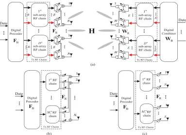
Consider a mmWave MIMO communication system as shown in Fig. 1(a), where both the transmitter and receiver adopt HBF with hybridly-connected structure. That is because the hybridly-connected structure is more energy effi-cient and the fully- and partially-connected structures are the special cases of it as shown in Fig. 1(b) and Fig. 1(c), respectively [6]. In this part, we take the hybridly-connected structure as an example to show the system parameters and signal processing. As shown in Fig. 1(a), the transmitter and receiver are equipped withNt=DNandNr=DMantennas,
respectively, whereD is the number of sub-arrays. N (M) andR(E) represent the numbers of antennas and RF chains of each sub-array at the transmitter (receiver), respectively. Moreover, the numbers of RF chains at the transmitter and
receiver areMt = DRandMr = DE, respectively. At the
transmitter, the data streams are first allocated to different RF chains by the digital precoderFB, then mapped to different
antennas through analog precoderFRimplemented by phase
shifters. At the receiver, the received signals first processed
by an analog combiner WR, then the baseband processor
performs digital combining using a digital combinerWBand
FIGURE 1. A mmWave MIMO communication system employing three different HBF structures. (a) Hybridly-connected structure. (b) Fully-connected structure. (c) Partially-connect structure.
different. For the fully-connected structure,FR(WR) is a
nor-mal matrix. For the partially-connected structure,FR (WR)
is a block digital matrix with each block just containing one column. For the hybridly-connected structure, FR (WR) is
a block digital matrix with each block containing multiple columns. In Section III, we will consider designing the pilot beam patterns for different HBF structures.
According to the mmWave channel measurements in [23], the AoAs/AoDs belong to large-scale fading, and the path gains belong to small-scale fading. Without loss of generality, it is assumed that the AoAs/AoDs are fixed during a frame
that contains K fading blocks, which means the variation
of the channel is only caused by the path gains in a frame. During the training period, the transmitter successively emits
Mttraining beams which generated byFR=fR,1, . . . ,fR,Mt
in a fading block, wherefR,iis theith column ofFR. Since
the receiver contains Mr RF chains, each training beam is received byMrbeams which generated byWR. It is assumed
that the pilot signals transmitted by different RF chains are orthogonal to each other in a fading block, i.e.,xi(k)xHi (k)=
PMt, wherexi(k)∈C1×Mtis the pilot sequence transmitted by beamfR,iandPdenotes the total power allocated equally for each pilot signal. Then, the received signals for all the beams in thekth fading block can be expressed as
Y(k)=WHRH(k)FRX(k)+N(k) , (1)
whereX(k) = [xT1(k), . . . ,xTM
t(k)]
T,N(k) = WH
R[n1,n2,
· · ·,nMt
, andniindicates a noise vector withCN 0, σn2IMt
.
CorrelatingY(k)withX(k)yields
¯
Y(k)=Y(k)XH(k)= P
MtW
H
RH(k)FR+ ¯N(k) , (2)
whereN¯(k)=N(k)XH(k).
Since the sparse scattering characteristic of the mmWave channel [24], [25], the geometric channel model withL scat-terers is adopted. Assuming that each scatterer contributes to a single resolvable path. The channel model can be written as [23] and [26]
H(k)=
r NrNt
L
L
X
l=1
αl(k)ar(θl)at(φl)H, (3)
whereαl(k) ∼ CN(0,1)indicate the complex gain of the
l-th path; k is used to index the time block in which the channel remains unchanged.φl=sin(φˆl) andθl =sin(θˆl) are the departure and arrival directions corresponding to azimuth AoDφˆl and AoAθˆlof thel-th path, respectively.at(φl) and
ar(θl) are the antenna array response vectors at the transmitter and receiver, respectively. For a uniform linear array (ULA), the antenna spacing is assumed to be half wavelength,at(φl) can be expressed as
at(φl)= 1 √
Nt
[1,ejπφl, . . . ,ejπ(Nt−1)φl]T. (4)
model in (2) can be rewritten in matrix form as
H(k)=ARD(k)AHT, (5)
where AR = [ar(θ1),· · · ,ar(θL)] ∈ CNr×L, AT =
[at(φ1),· · ·,at(φL)] ∈ CNt×L, and D(k) =
q
NrNt
L diag
(α1(k) ,· · · , αL(k))∈CL×L.
III. SUBSPACE FITTING BASED CHANNEL ESTIMATION
In this part, we will develop three channel estimation methods based on subspace fitting for the mmWave hybrid precoding MIMO system. Meanwhile, the pilot beam pattern is designed for different HBF structures. Although, the structures of the analog precoding and combining matrices are different for these three hybrid beamforming structures as shown in Fig. 1, it has no effect on channel estimation.
A. SUBSPACE FITTING METHOD
As aforementioned, the path angles and path gains belong to large-scale fading and small-scale fading, respectively. Leveraging this property, the channel estimation based on the subspace fitting is divided into two stages. In the first stage, the path directions are estimated by using the subspace fitting method. In the second stage, the path gains are estimated by exploiting LS method.
In the first stage, the AoAs and AoDs are estimated as follows. According to (2) and (5), the received signalY¯(k)
in thekth fading blocks can be vectorized as
y(k)= P
Mt
BT ⊗A·vec(D(k))+n(k)
= P
Mt
BT A
| {z }
G(θ,φ)
·vecd(D(k))+n(k) , (6)
where A = WHRAR, B = AHTFR, and n(k) =
vec(N(k)). The first equation is obtained based on the fact
that vec(XYZ)= ZT ⊗X
·vec(Y). The second equation holds becauseD(k)is a diagonal matrix, and vecd(D(k))=
q
NrNt
L [α1(k) ,· · ·, αL(k)]
T. During a frame, the receiver
collect the received signal and calculate the covariance matrix
Ry=E
h
y(k)y(k)Hi' ¯Ry= 1
K
K
X
k=1
y(k)y(k)H, (7)
which will be used to generate the signal and noise subspace. Substituting expression (6) into (7), and defining α(k) = vecd(D(k)), we have
Ry =G(θ,φ)E
h
α(k)α(k)HiG(θ,φ)H +Rn
=G(θ,φ) 3αG(θ,φ)H +σ2IMtMr, (8)
where 3α = P
Mt 2
NrNt
L diag σ
2
1,· · ·, σK2
, Rn =
En(k)n(k)H, and the second line of (10) holds because the columns ofWRare orthogonal. It is assumed thatGis a
column full rank matrix, the eigenvalue decomposition ofRy can be written as
Ry=Udiag λ1,· · ·, λMtMr
UH, (9)
where diag λ1,· · · , λMtMr
is a diagonal matrix containing the eigenvalues of Ry in decreasing order; Theith column of matrixUis an eigenvector corresponding to theith eigen-value. Meanwhile, the matrixUcan be divided into two parts, i.e.,U = [Us|Un], whereUs andUndenote the signal
sub-space and noise subsub-space, respectively. In an ideal situation, the signal subspaceUsis equal to the column space of matrix
G(θ,φ), such that
span{Us} = span{G(θ,φ)}, (10)
which means there is a full rank matrixT∈CL×L that satis-fiesUs=G(θ,φ)T. Meanwhile, signal subspaceUs
orthog-onal to noise subspaceUn, which impliesUHnG(θ,φ) =0.
However, the actual training signal received by the receiver is finite, and the covariance matrix of the received signal can be expressed asR¯yin (7). The eigenvalue decomposition ofR¯y can be expressed as
¯
Ry=[U¯s| ¯Un]diag λ¯1,· · ·,λ¯MtMr
[U¯s| ¯Un]H, (11)
where U¯s ∈ CMtMr×L and U¯n ∈ CMtMr×(MtMr−L)
are the actual signal and noise subspaces, respectively; diag λ¯
1,· · ·,λ¯MtMr
is a diagonal matrix of eigenvalues arranged in decreasing order. Since the effects of noise, signal subspaceU¯sdoes not equal to the column space of the matrix
G(θ,φ), andU¯nHG(θ,φ)6=0.
In order to tackle these problems, signal subspace fitting is an effective method. The mathematical estimation criterion is to find the best LS fit of the two subspaces which can be expressed as follows:
n
ˆ
θ,φˆ,T¯o=arg min ¯
θ,φ¯,T¯
U¯s−G θ¯,φ¯T¯ 2
F, (12)
whereθ¯ andφ¯ are the subsets of the candidate departure and arrival path direction sets, respectively.T¯ ∈ CL×L is a full rank matrix, which can be written asT¯ =G θ¯,φ¯†¯
Us, and
substituting it in (12), the path directionsθˆ and φˆ can be obtained by solving
n
ˆ
θ,φˆo =arg min ¯
θ,φ¯
¯
Us−G θ¯,φ¯G θ¯,φ¯
†¯
Us 2
F
=arg max
¯
θ,φ¯
trnPG θ¯,φ¯U¯sU¯Hs o
, (13)
wherePG θ¯,φ¯ = G θ¯,φ¯Gθ¯,φ¯
†
model, the departure and arrival directions of all
possi-ble paths can be denoted as nφ˜j
oGφ
j=1 and n
˜ θi
oGθ
i=1, where Gφ andGθ indicate the number of angle sampling points, which determine the angular resolutions of the departure and arrival path (i.e., 1φ and 1θ), respectively. Define
PG
˜ θi,φ˜j
= Gθ˜i,φ˜j
Gθ˜i,φ˜j
†
, and qθ˜i,φ˜j
=
trnPG
˜ θi,φ˜j
¯ UsU¯Hs
o
denotes the entries of matrixQ
corre-sponding to the path directionsθ˜iandφ˜j. Substituting
n
˜ φj
oGφ
j=1
andnθ˜i
oGθ
i=1 into (13), the departure and arrival path
direc-tions can be obtained by scanning the directional spectrum
n qθ˜i,φ˜j
,i=1,· · ·,Gθ,j=1,· · ·,Gφoand locating the largestL poles. Since the eigenvalues{λi}L
i=1and{λi}iM=tML+r1
corresponding toU¯sandU¯ncan be clearly distinguished from
the magnitudes, the number of paths L is assumed to be
known.
Moreover, sinceUH
nG(θ,φ) = 0, we can also estimate
the departure and arrival path directions using the noise subspace fitting method. Both θˆ andφˆ can be obtained by solving
n
ˆ
θ,φˆo=arg min ¯
θ,φ¯
¯
UHnG θ¯,φ¯ 2
F
=arg min
¯
θ,φ¯
trnU¯HnG θ¯,φ¯G θ¯,φ¯HU¯n o
. (14)
Since the subspace fitting method and 2-D BMUSIC method [18] are similar in nature, we will not analyze this method separately later in this article. In what follows, the subspace fitting method refers to the signal subspace fitting method unless otherwise specified.
In the second stage, when the departure and arrival path directions φˆ andθˆ are fixed by using the subspace fitting method, the direction matrix can be expressed asGnθˆ,φˆo. Then, the path gains are estimated using the LS method. According to (6), the path gain vector can be obtained by
ˆ αk=
Mt P
Gθˆ,φˆHGθˆ,φˆ
−1
Gθˆ,φˆHy(k) . (15)
The mmWave MIMO channel estimation based on subspace fitting method is summarized in Algorithm 1.
B. LOW-COMPLEXITY OMP ALGORITHM
As mentioned above, the subspace fitting method is a nonlin-ear multidimensional optimization problem, which requires a two-dimensional search in the angular domain, and the computational complexity is very high. For this reason, we propose a low-complexity OMP algorithm. Similar to the subspace fitting method, this algorithm can also be divided into two stages. In the first stage, the AoAs and AoDs are estimated by using the OMP method. Note that, the proposed low complexity OMP-based channel estimation method is different from the OMP-based method in [12].
Algorithm 1Subspace Fitting mmWave Channel Estimator
1: Initialization: Precoding and combining matricesFRand
WR. The number of paths L. Search girdsθ˜iandφ˜jwithin 9θ and9φ, respectively, wherei ∈ {1, . . .Gθ}andj ∈
1, . . .Gφ .
First stage: Estimate the path directions
2: Calculate sample covariance matrixR¯yaccording to (7).
3: Eigenvalue decomposition of matrixR¯y
¯
Ry=[U¯s| ¯Un]diag λ¯1,· · · ,λ¯MtMr
[U¯s| ¯Un]H.
4: Compute Gθ˜i,φ˜j
andPG
˜ θi,φ˜j
according to (6) and (13), respectively.
5: Scan q
˜ θi,φ˜j
to find the L poles corresponding to
n
ˆ θl,φˆl
oL
l=1.
Second stage: Estimate the path gains
6: Compute AˆR =
h
ar(θˆ1),· · ·,ar(θˆL)
i
, AˆT =
h
at(φˆ1),· · ·,at(φˆL)
i
, and Gθˆ,φˆ according to
(6).
7: for1≤k≤Kdo
8: Estimate the path gain vectorαˆkaccording to (15).
9: Channel in thekth fading block is estimated as ˆ
H(k)= ˆARdiag αˆk
ˆ
AHT.
10: end for
We divide the two-dimensional search problem into multi-ple one-dimensional search problems, which helps reduce the overall computational complexity. When the path direc-tions are fixed, the second stage is similar to Algorithm 1, which will not be illustrated in this part. The procedures of the first stage are illustrated in Algorithm 2. From Algo-rithm 2, we know that the low-complexity OMP method contains three steps. In the first step, we first randomly generate an initial arrival direction, i.e.,θ˜init ∈ 9θ. Then,
compute nGθ˜init,φ˜j
oGφ
j=1, n
PG
˜ θinit,φ˜j
oGφ
j=1, and scan
trnPG
˜ θinit,φ˜j
¯
Uress U¯ressHoGθ
j=1to find the maximum value
that corresponding to a temporary departure directionφˆtmpof
thelth path. Note that, we can also first generate an initial departure direction, i.e.,φ˜init ∈ 9φ, which have no effect
on the performance of the proposed algorithm. In the second step, whenφˆtmpis found, the similar process as the first step
can be used to find the arrival directionθˆ
lof thelth path. In the third step, we replaceθ˜
Algorithm 2Low-Complexity OMP Algorithm
1: Initialization: Precoding and combining matricesFRand
WR. The number of paths L. Search girdsθ˜iandφ˜jwithin 9θ and9φ, respectively, wherei ∈ {1, . . .Gθ}andj ∈
1, . . .Gφ .Gres=Empty Matrix.U¯ress= ¯Us.
First stage: Estimate the path directions
2: Calculate sample covariance matrixR¯yaccording to (7).
3: Eigenvalue decomposition of matrixR¯y
¯
Ry=[U¯s| ¯Un]diag λ¯1,· · ·,λ¯MtMr
[U¯s| ¯Un]H. 4: for1≤l≤Ldo
5: Setp 1:
Generate an arrival direction randomly, i.e.,θ˜init∈9θ.
Compute Gθ˜init,φ˜j
and PG
˜ θinit,φ˜j
according to (6) and (13), respectively.
Scan trnPG
˜ θinit,φ˜j
¯ Ures
s U¯ress Ho
to find the
maximum value corresponding toφˆtmp.
6: Setp 2: ComputeGθ˜
i,φˆtmp
andPG
˜ θi,φˆtmp
as step (5).
Scan trnPG
˜ θi,φˆtmp
¯ Ures
s U¯ress Ho
to find the
maximum value corresponding toθˆl.
7: Setp 3:
ComputeGθˆ
l,φ˜j
andPG
ˆ θl,φ˜j
as step (5).
Scan trnPG
ˆ θl,φ˜j
¯
Uress U¯ressHo
to find the
maxi-mum value corresponding toφˆl.
8: ComputeGθˆ
l,φˆl
, andGres = h
GresG
ˆ θl,φˆl
i
.
9: T¯ =G†resU¯saccording to (14). 10: U¯ress= U¯s−GresT¯
U¯s−GresT¯
F
.
11: end for
C. LOW-COMPLEXITY SUBSPACE FITTING ALGORITHM As illustrated above, we know that the low-complexity OMP method transforms a two-dimensional search problem into multiple simple one-dimensional search problems, which helps reduce the computational complexity. However, for this algorithm, when the path directions are strongly correlated, the estimation accuracy of the path direction will be greatly declined. It is for this reason that we develop an improved low-complexity subspace fitting method in this part, which combines the advantages both of the low-complexity OMP method and subspace fitting method, and makes a trade-off between the computational complexity and performance of the channel estimation.
According to (10), if the noise factor can be ignored,
the signal subspace Us is equal to the column space of
G(θ,φ). From this result, we know that if the estimated path directions are close enough to the real path directions,
i.e.,nθˆl ≈θl,φˆl ≈φl
oL
l=1, then we have PL
l=1q
ˆ θl,φˆl
≈
L. It is clear that this result can be used to determine the estimation accuracy of the path directions. In this part, we will use it to determine whether the performance of the OMP
method is affected by the path correlation in step 22 as shown in Algorithm 3. Different from Algorithm 1 and Algorithm 2, the low-complexity subspace fitting method estimate the path directions by combining the OMP method and subspace fitting method. These procedures are illustrated in detail in Algorithm 3.
In Algorithm 3, we first roughly estimate the path direc-tions using the OMP scheme as shown in step 5, and then search in the adjacent areas to further determine the path directions as presented in steps 6-18. Note that, we assume that qθ˜i+1,φ˜j
and qθˆltmp,φ˜j+1
are the largest in step
6 and step 13, respectively. In fact, if we assumeqθ˜i−1,φ˜j
andqθˆltmp,φ˜j−1
are the largest, the following processes are similar. Similar to Algorithm 2, we eliminate the contri-bution of the selected paths in step 19. As aforementioned, the estimation accuracy of the path directions is affected by the path correlation for the OMP method. Therefore, we judge whether the estimated path directions are affected by the path correlation as shown in step 21, where Thr is a threshold be used to determine whether the performance of the OMP method is affected by the path correlation.
If L
P
l=1
qθˆl,φˆl
< Thr, we consider further estimating the path directions according to the subspace fitting method as shown in step 22, where θ˜ and φ˜ are the sets of the path direction, which were not scanned in the previous steps. That is, even the performance of the previous steps is not good, the computational complexity of this method is comparable to Algorithm 1.
D. PILOT BEAM PATTERN DESIGN As illustrated above, we know that both tr
PG θ¯,φ¯U¯sU¯Hs
and trnU¯HnG θ¯,φ¯G θ¯,φ¯HU¯n o
depend on the value of
G θ¯,φ¯, andG θ¯,φ¯is related to pilot beam pattern design,
such that FR and WR, which implies the performance of
the channel estimate method relies onFR andWR. This is
because the pilot beam pattern design can be leveraged to improve the SNR of the pilot signals [27], thereby improv-ing the performance of the channel estimation. Moreover, the proper pilot beam pattern design helps avoid the spectrum ambiguity [18].
As aforementioned, for the mmWave MIMO system with hybrid beamforming structure, the pilot beam patter mainly depends on the analog precoder. Therefore, in this paper, we just consider designing the analog precoder and the digital precoder is assumed to be an identity matrix. For mmWave hybrid precoding MIMO system with hybridly connected structure, the analog precoding matrix FR is a
block diagonal matrix, which means the beam pattern of each sub-array is independent, and the number of beams formed by each sub-array is equal to the number of RF chains [6]. Without loss of generality, it is assumed that at the transmitter the antenna array contains two sub-arrays,
Algorithm 3Low-Complexity Subspace Fitting Algorithm
1: Initialization: Precoding and combining matricesFRand
WR. The number of paths L. Gres = Empty Matrix.
¯
Uress = U¯s. Search girds θ˜i andφ˜j within9θ and9φ, respectively, wherei∈ {1, . . .Gθ}andj∈1, . . .Gφ .
First stage: Estimate the path directions
2: Calculate sample covariance matrixR¯yaccording to (7).
3: Eigenvalue decomposition of matrixR¯y
¯
Ry=[U¯s| ¯Un]diag λ¯1,· · ·,λ¯MtMr
[U¯s| ¯Un]H. 4: for1≤l≤Ldo
5: Estimateθ˜iandφ˜jas steps 5-7 in Algorithm 2.
6: Compute q
˜ θi,φ˜j
, q
˜ θi+1,φ˜j
, and q
˜ θi−1,φ˜j
ac cording to (13), and find the maximum value of them.
7: Ifqθ˜i+1,φ˜j
is the maximum.
8: repeat
9: Letθˆltmp= ˜θi+1, andqtmp=q
ˆ θtmp
l ,φ˜j
.
10: i=i+1, obtainqθ˜i+1,φ˜j
.
11: Untilqθ˜i+1,φ˜j
<qtmp.
12: Obtain qθˆltmp,φ˜j+1
and qθˆltmp,φ˜j−1
based on (13) and compare withqtmp.
13: Ifqθˆltmp,φ˜j+1
is the maximum.
14: repeat
15: Letφˆtmpl = ˜φj+1, andqtmp=q
ˆ θtmp
l ,φˆ
tmp
l
.
16: j=j+1, obtainqθˆitmp,φ˜j+1
.
17: Untilqθˆitmp,φ˜j+1
<qtmp. 18: Letθˆl = ˆθltmpandφˆl = ˆφltmp.
19: UpdateU¯res
s as steps 8-10 in Algorithm 2. 20: end for
21: If
L
P
l=1 qθˆl,φˆl
<Thr
22: Compute nqθ˜i,φ˜j
,i=1, . . .Gθ,j=1, . . . ,Gφo, and scanqθ˜i,φ˜j
to locate theLpoles corresponding tonθˆl,φˆl
oL
l=1.
RF chains, then the analog precoding matrix can be
writ-ten as FR =
˜
FR1 0
0 F˜R2
, F˜R1∈CN×R and F˜R2∈CN×R
denote the analog precoding matrix for the first and second sub-arrays respectively, which can be designed independent, and the total number of beams is 2R. Note thatF˜R1andF˜R2
should satisfy F˜HR1F˜R1 = IR and F˜HR2F˜R2 = IR in order to avoid the spectrum ambiguity. Since two sub-arrays are exactly the same, we can merge F˜R1 andF˜R2, i.e., F˜R = h
˜ FR1 F˜R2
i
. That is, when designing the pilot beam pattern, an antenna array contains two identical sub-arrays with each
equipped with R RF chains, which is equivalent to one
[image:7.576.302.537.63.196.2]antenna array withMt = 2RRF chains. From this perspec-tive, we know that the hybridly-connected structure with two
FIGURE 2. Illustration of the deviation between the selected codebook and beam sector.
identical sub-arrays with each containingRRF chains can be viewed as the fully-connected structure with 2RRF chains. Therefore, the beam pattern design for the fully-connected structure is the same as that of its hybridly-connected counterpart.
Next, we consider designing the pilot beam pattern for mmWave MIMO system with the hybridly-connected struc-ture. It is assumed that the phase shifter has a sufficiently high resolution, and the ULA with half-wavelength is applied at the transmitter and receiver, then the antenna array response can be expressed as (4). It is clear that the beamforming codebooks based on DFT satisfy the orthogonal condition. According to [28], the beamforming codebooks based on DFT can be expressed as
FDFT=
at(ϕ˜1),· · · ,at(ϕ˜N)
, (16)
wherenϕ˜i= 2
N(i−1)−1
oN
i=1, and the value of
˜ ϕi is uni-formly distributed in [−1,1). It is assumed that the beam-forming sector at the transmitter satisfy9φ⊆[−1,1), which
is symmetric about ϕ˜i = 0. In order to match the DFT
codebook and the beamforming sector, we assume that the range of beamforming sector is multiples of1ϕ˜, i.e.,φend−
φbegin = Nb1ϕ˜, where1ϕ˜ is the interval betweenϕ˜i and
˜
ϕi+1, and Nb is the number of beams which usually equal
to the number of RF chains. However,ϕ˜ = ϕ˜1,· · ·,ϕ˜N does not symmetric aboutϕ˜i =0. As Fig. 2 show, the devi-ation between the selected codebook and beam sector isϕ˜1. Therefore, the beam sector9φ can be further expressed as 9φ = ϕ˜j+ ˜ϕ1,ϕ˜j+M
t- 1+ ˜ϕ1
, where ϕ˜j is the candidate codebook closest toφbegin. Since the beam formed by the
can-didate codebook just wrap around, the orthogonality among {at(ϕ˜i+ ˜ϕ1)}Ni=1 would not be destroyed. Based upon the
above discussions, the beamforming matrixF˜Rcan be written
as
˜
FR=at ϕ˜j+ ˜ϕ1,· · ·,at ϕ˜j+Mt−1+ ˜ϕ1 .
(17)
In addition, we consider designing the pilot beam pattern for the mmWave MIMO system with the partically-connected structure as shown in Fig. 1(c). For this structure, the analog precoder is a block digital matrix, and each block just contains one column, which means the pilot beam pattern design for each sub-array is not constrained by orthogonality. There-fore, we consider designing the beam uniform distribute in the beamforming sector, and the interval between any two adjacent beams is φend−φbegin
Mt. Note that, the beam
pattern design for the receiver is similar to the transmitter. However, considering that phase shifters with infinite pre-cision are practically unrealistic, we provide another pilot beam pattern design method for the mmWave MIMO system with the hybridly-connected structure. It is assumed that the phase shifters haveB=5 bits of precision, i.e., phase control candidates of n2πb
2B ,b=0, . . . ,2B
−1o. We further assume
the number of RF chains at the transmitter isR = 4, then
the quantized analog precoder can be selected from At =
h
¯
at(0),· · ·,a¯t(2π(2
B−1) 2B )
i
, where a¯t(w) indicates the array
response vector of the sub-array in the hybridly-connected structure, which can be expressed as
¯ at(w)=
1 √
N[1,e
jw, . . . ,ej(N−1)w]T, (18)
where w = 2πb
2B , b = 0, . . . ,2B
−1. Then, the
beamform-ing matrix F =
˜
FR1 0
0 F˜R2
with infinite precision can be
approximated as the product of analog quantized precoding matrix and digital precoding matrix, where F˜R1 ∈ CN×R andF˜R2 ∈ CN×R are the first and lastRcolumns ofF˜Rin
(17), respectively. The quantized analog precoder and digital precoder can be obtained by solving
n
FoptBn,F¯optRno=arg min FBn,F¯Rn
˜
FRn− ¯FRnFBn
2
F
s.t.F¯Rn⊂At, n∈ {1,2}. (19)
However, the complex non-convex constraint of the analog precoder makes it difficult to find a closed-form solution. Fortunately, the OMP method has been proven to solve such problems. For a comprehensive presentation, please refer to [4]. According to the OMP method, the normalizedFBn can be expressed as
FoptBn = √
R FBn
¯ FoptRnFBn
2
F
. (20)
It can be inferred from the above result that the beamforming matrix in (17) with infinite precision approximated as the product of the digital precoding matrix and the quantized analog precoding matrix. Moreover, the beam pattern design for the receiver is similar to that of the transmitter. It is noted that the pilot beam pattern design with quantized phase shifters for the hybridly-connected structure is also applicable to the fully- and partically-connected structures.
E. MULTI-USER CHANNEL ESTIMATION
This section considers uplink channel estimation for the multi-user mmWave MIMO system where HBF structures in Fig. 1 are employed at both the base station (BS) andU
users. The BS is equipped withNrantennas andMrRF chains, and each user is equipped withNtantennas and one RF chain. In the preceding sections, we have assumed that a frame can
be divided intoK fading blocks, and the channel remains
unchanged in each fading block. Then, it is further assumed that each user successively emitsMtidentical pilot sequences, such that theuth user transmits a pilot sequencesu∈ C1×Ts
using thetth beamfkt,u. Note that all users are synchronized before transmission. At the BS, the received training signal in thetth training beam can be expressed as
Ykt =WHH¯kF¯ktS+WHNkt, (21)
where W ∈ CNr×Mr is the beamforming matrix at the
BS,H¯k = [Hk1, . . . ,HkU] withHku denoting the channel
between the BS and user u in the kth fading block, S =
[sT1, . . . ,sTU]T ∈ CU×Ts, F¯
kt is a block diagonal matrix
¯
Fkt = diag fkt,1, . . . ,fkt,U
, andNkt is the additive white Gaussian noise matrix. The pilot sequences transmitted by different users are assumed to satisfysusHu¯ = ¯PTsδu,u¯, where
¯
Pis the transmit power of user andδu,u¯is the Kronecker delta function. CorrelatingYkt withSyields
¯
Ykt =YktSH = ¯PTsWHH¯kF¯kt +Zkt, (22) whereY¯kt ∈CMr×U,Zkt =WHNktSH. As can be seen from this result, theuth column ofY¯kt can be written as
¯
ykt,u= ¯PTsWHHkufkt,u+zkt,u, (23) wherezkt,u is theuth column ofZkt. According to (5),Hku can be written as
Hku=AR,kuDkuAHT,ku, (24)
where AR,ku = ar(θku,1),· · ·,ar(θku,L) ∈ CNr×L,
AT,ku =
at(φku,1),· · ·,at(φku,L)
∈ CNt×L, and D
ku =
q
NrNt
L diag αku,1,· · ·, αku,L
∈
CL×L. Substituting (24) into (23) gives rise to
¯
ykt,u = ¯PTsWHAR,kuDkuAHT,kufkt,u+zkt,u
= ¯PTs
AHT,kufkt,u
T
⊗WHAR,ku
vec(Dku)+zkt,u
= ¯PTs
AHT,kufkt,u
T
WHAR,ku
vecd(Dku)+zkt,u.
(25)
If all theMt vectors are stacked to form a column, the mea-surement vector can be expressed as
¯
yku=[y¯Tk1,u, . . . ,y¯TkT,u]T
= ¯PTsBTkuAkuvecd(Dku)+zku, (26) where Bku = AHT,kuFku, Fku = [fk1,u, . . . ,fkMt,u], and
zku = [zTk1,u, . . . ,zTkMt,u]
T. Obviously, Eqs. (26) and (6) are
multi-user mmWave MIMO system can be translated into channel estimation for individual users. That is, the pro-posed channel estimation methods are equally applicable to multi-user channel estimation.
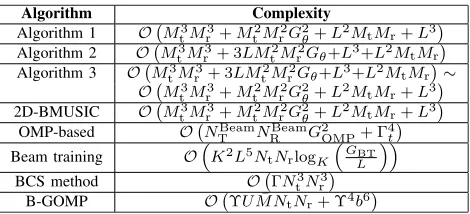
F. COMPUTATIONAL COMPLEXITY COMPARISON
In this subsection, we analyze the complexities of the pro-posed algorithms and its comparative counterparts.
As can be seen from Algorithm 1, the computational com-plexity of the above method is mainly composed of three parts. The first part is due to eigenvalue decomposition of the covariance matrix of the received signal in step 3, which is O Mt3Mr3. The second part stems from multi-dimensional search in step 4 and 5, which isO Mt2Mr2GθGφ. The third part is used for estimating the path gains in step 8, which is O L2MtMr+L3. It can inferred from these results that the computational complexity of the subspace fitting method is the same as that of the 2-D BMUSIC method. In general, the number of columns of Us is less than Un. Therefore,
we consider the complexity of the subspace fitting method lower than that of the 2-D BMUSIC method.
Similar to the subspace fitting method, the computational complexity of the low-complexity OMP method is also due to three parts, where the first and third parts are the same as those of the subspace fitting method. In the second part, the two-dimensional search is divided into multiple one-two-dimensional
searches. We assume Gθ = Gφ, and then the
computa-tional complexity isO 3LMt2Mr2Gθ, which is much lower thanO Mt2Mr2G2θ. It is clear that difference in complexity between these two methods increases with the angular res-olution. Moreover, since Algorithm 3 enjoys the combined advantages of the low-complexity OMP method and high accuracy of the multi-dimensional search, the complexity of Algorithm 3 lies between those of Algorithms 1 and 2. In a sense, it depends on path correlation.
For the beam training method, logK¯
GBT
L
is the
num-ber of layers of the hierarchical codebook, where K¯ is the
number of beamforming vectors in each stage, and GBT
indicates the number of uniform grid points. Moreover, the number of candidate vectors in each layer is K L¯ for both the transmitter and receiver. Since only one path can be determined in each beam training stage, these
adap-tive beam training stages need to be repeated L times,
the complexity is OK¯2L3N tNrlogK¯
GBT
L
. Meanwhile, the contributions of the previously estimated paths need to be subtracted during each iteration, and the complexity is OK¯2L5NtNrlog
¯
K
GBT
L
. Hence the total complexity
order isOK¯2L5N tNrlogK¯
GBT
L
.
The main computational costs of the OMP-based chan-nel estimation scheme lie between those of the search of AoDs/AoAs and the LS estimator. It is noted that,
solving the LS estimation requires O 04
t
, where 0t
[image:9.576.301.536.92.199.2]is the number of iterations. Hence, its complexity is O NTBeamNRBeamG2OMP+0t4, where NTBeam and NRBeam
TABLE 1.Computational complexities of the proposed and comparative algorithms.
represent the numbers of pilot beam patterns at the transmit-ter and receiver, respectively.GOMPis the number of angle
sampling points of virtual AoAs/AoDs.
For the Bayesian compressive sensing (BCS) method, it requires matrix operations including matrix inversion and multiplication, etc. The main computational costs are attributed to the matrix inversion operation, and matrix6 ∈
CNtNr×NtNr needs to be inverted in each iteration. Therefore, its computational complexity is in the order ofO 0Nt3Nr3, where0is the number of iterations.
For the generalized block OMP (G-BOMP) algorithm [29], the main computational complexity stems from the inner products of matrices and LS estimation, yielding complexity orders ofO ϒUM N¯ tNr
andO ϒ4b6
, respectively. There-fore, the total complexity order isO ϒUM NtNr¯ +ϒ4b6, wherebis the dimension of the non-zero square block con-tributed by each path,ϒ is the number of iterations, andM¯
is the number of training slots in each fading block. Based upon the above discussions, the computational complexities of the comparative channel estimation methods are detailed in Table 1.
IV. SIMULATION RESULTS
In this section, we evaluate the performance of the proposed algorithms in mmWave MIMO systems with different hybrid beamforming structures. The uniform linear arrays (ULA) with half wavelength antenna spacing is adopted at the transmitter and receiver. We model the propagation environ-ment as illustrated in Section II, where the path directions are randomly generated within [−1,1]. The signal-to-noise
ratio (SNR) in the plots is defined as P
Ntσ2. It is assumed
that the beamforming sectors at the transmitter and receiver are9φ =[−0.2188,0.2188] and9θ =[−0.1875,0.1875], respectively [18]. Moreover, the grid resolution for the
phys-ical azimuth AoD and AoA are 1φ and1θ, respectively.
Indoor and outdoor measurements of mmWave channel indi-cate that the resolvable paths most likely ranges from 1 to 4 [30], [31]. In the following simulations, we consider the
mmWave channel model with L = 1 and L = 3 two
FIGURE 3. Channel estimation performance of different algorithms in hybridly-connected structure versus the SNR in single path scenario, i.e.,L=1.
error (NMSE), which can be calculated as
NMSE=10log10
E
H− ˆH
2
F
kHk2F
. (27)
where Hˆ denotes the estimated channel. Furthermore,
the NMSE for multi-user channel estimation can be expressed as
NMSEmu=10log10
E
PU
u=1
Hu− ˆHu 2
F
PU
u=1kHuk2F
, (28)
where Hˆu is the estimated channel of the uth user. In what follows, the average NMSE plotted are averaged over
5000 frames withK=20.
First, we evaluate the performance of the proposed algo-rithms for mmWave MIMO system with hybridly-connected structure as shown in Fig. 1(a). The ULA at the transmitter consists ofD=2 sub-arrays, each sub-array equippedR=4 RF chains, and the totally number of antennas isNt = 64.
The ULA at the receiver contains D = 2 sub-arrays, each
sub-array equippedK =2 RF chains, and the totally number of antennas isNr = 32. Moreover, the pilot beam pattern is designed as shown in Section III-D. Since the channel estima-tion of mmWave MIMO system depends on the design of the pilot beam pattern, many existing channel estimation meth-ods are based on the fully-connected hybrid beamforming architecture, which cannot be directly applied to the mmWave MIMO system with hybridly-connected structure. In this part, we compare the performance of the proposed methods with 2-D BMUSIC method in [18].
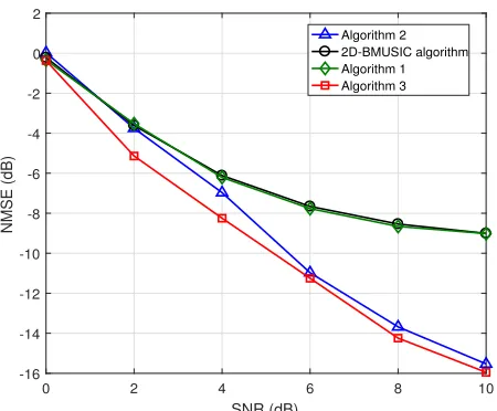
In Fig. 3, we present the performance of the proposed channel estimation methods in single path scenario. For the 2-D BMUSIC and the proposed subspace fitting methods,
1φ = 0.0055 and 1θ = 0.0047. For the low-complexity
[image:10.576.45.270.62.248.2]OMP and low-complexity subspace fitting methods,
FIGURE 4. Channel estimation performance of different algorithms in hybridly-connected structure versus the SNR in multiple paths scenario, i.e.,L=3.
1φ = 0.0022 and 1θ = 0.0019. As can be observed
from Fig. 3, the performance of the subspace fitting method is slightly better than that of the 2-D BMUSIC method. Moreover, both the low-complex OMP and subspace fitting methods outperform 2-D BMUSIC counterpart significantly. This is because these methods have a higher angular resolu-tion. According to the aforementioned discussions, the dif-ference in complexity among Algorithms 1, 2 and 3 due
mainly to the angle search process. Since Gθ = Gφ =
80, then the computational complexity of angle search in Algorithm 1 and 2 areO Mt2Mr2G2θandO 3LMt2Mr2Gθ, respectively. Note that, although the angular resolution of Algorithms 2 and 3 is 2.5 times that of Algorithm 1 and the 2-D BMUSIC algorithm, 7.5LGθ is still less thanG2θ. It is known from this result that the computational complexity of Algorithm 2 is lower than those of Algorithm 1 and the 2-D BMUSIC method. Meanwhile, it is observed that the performance of Algorithm 3 is slightly better than that of Algorithm 2. And whenL=1, one does not need to consider the correlation among paths, which means the computational complexity of Algorithm 3 is similar to that of Algorithm 2.
In Fig. 4, we compare the performance of the proposed methods with 2-D BMUSIC method in multiple paths sce-nario, i.e.,L = 3. From this figure, we observe that when
1φ = 0.0055 and1θ = 0.0047, the performance of the
FIGURE 5. Channel estimation performance of different algorithms in fully-connected structure versus the SNR in multiple paths scenario, i.e.,L=3.
FIGURE 6. Channel estimation performance of different algorithms in partially-connected structure versus the SNR in multiple paths scenario, i.e.,L=3.
In Fig. 5, the mmWave MIMO system with the
fully-connected structure is considered, where Nt ×Nr =
32×16. Moreover, the numbers of RF chains at the transmitter
and receiver are Mt = 8 and Mr = 4, respectively. The
pilot beam pattern is designed as shown in Section III-D. For the fully-connected structure, we compare the performances of the proposed algorithms with those of the 2-D BMUSIC method [18], OMP-based method (NtBeam=16,NrBeam =8,
andGOMP = 80) [12], beam training method (GBT = 96,
K =2) [8], and BCS method. Note that, due to the limitations of the algorithm, it is difficult to ensure that all the algorithms adopt the same angular resolution. For the proposed methods,
the OMP-based method and the 2-D BMUSIC method,1φ=
0.0055 and1θ = 0.0047. For the beam training method,
1φ = 0.0046 and 1θ = 0.0039. For the BCS method,
FIGURE 7. Performance of the low-complexity OMP algorithm with different angular resolutions in the multi-path scenario, i.e.,L=3.
the channel is based on the beamspace model with1φ =
0.0625 and1θ = 0.125. It is observed from Fig. 5 that the
proposed low-complexity OMP method (Gφ = Gθ = 80)
outperforms the OMP-based method when SNR > 2 dB.
Meanwhile, the low-complexity OMP method surpasses the beam training method. Note that, according to the discussions in Section III-F, the computational complexity of the pro-posed low-complexity OMP method is approximately equal to 7.70×10⁵, and for the beam training and OMP-based methods are approximately equal to 2.48×10⁶and 8.22×10⁵, respectively. It is apparent that the computational complex-ity of the proposed low-complexcomplex-ity OMP method is the smallest. In addition, the proposed subspace fitting method outperforms its 2-D BMUSIC and BSC counterparts, and the performance of the low-complexity subspace fitting method is very close to that of the subspace fitting method. The computational complexities of the proposed subspace fitting method, the BSC method, and the 2-D BMUSIC method are 6.58× 10⁶, 2.68× 10⁹ (0 = 20), and 6.58 ×10⁶, respectively, while the complexity of the low-complexity subspace fitting method falls between those of the BSC and subspace fitting methods. In summary, it is observed that the proposed methods have certain advantages in computational complexity and estimation accuracy.
In Fig. 6, the mmWave MIMO system with the partially-connected structure is considered, whereNt×Nr=
64 × 32. Furthermore, the number of sub-arrays at the
transmitter and receiver areMt=8 andMr=4, respectively.
As we can see from Fig .6, when1φ =0.0055 and1θ =
0.0047, the performance of the proposed low-complexity
OMP method and low-complexity subspace fitting method is close to the multi-dimension search methods, such as 2-D BMUSIC method and subspace fitting method. Moreover, the performance of subspace fitting method outperforms 2-D BMUSIC method.
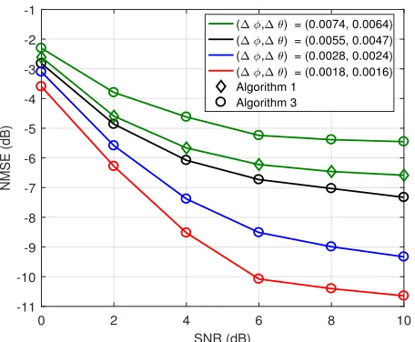
[image:11.576.46.270.304.488.2]FIGURE 8. Performance of the low-complexity subspace fitting algorithm with different angular resolutions in the multi-path scenario, i.e.,L=3.
and the system parameter configuration is the same as in Fig. 4. As we can see from Fig. 7, the estimation accu-racy of the channel is positively related to the scanning resolution. However, when the scanning resolution reaches a certain accuracy (i.e.,1φ = 0.0028 and 1θ = 0.0024), increasing the resolution has less effect on the performance. Meanwhile, we observe that the performance of the subspace fitting method with(1φ, 1θ) = (0.0074, 0.0064)
outper-forms the low-complexity OMP method with (1φ, 1θ) =
(0.0018, 0.0016). This is because the performance of the low-complexity OMP method is effected by the path corre-lation. Combined with the simulation results in single path scenario, we can know that this algorithm is more suitable for the scenario with single path or low path correlation.
In Fig. 8, the performance of the low-complexity sub-space fitting method with the different scanning resolution are evaluated, and the system parameter configuration is
the same as in Fig. 4. Fig. 8 indicates, when(1φ, 1θ) =
(0.0074, 0.0064), the performance of the low-complexity subspace fitting method is very close to subspace fitting algorithm. Moreover, increasing the angular resolution can effectively improve the channel estimation accuracy, which indicates that this method effectively makes up for the defect that the low-complexity OMP method is sensitive to the path correlation, and makes a trade-off between the computational complexity and performance.
[image:12.576.305.528.63.246.2]Fig. 9 compares the pilot beam pattern design and the DFT codebook for different algorithms. As can be observed from the figure, the performance of the proposed pilot beam pattern design for the proposed methods outperforms that of the DFT codebook. This is because the deviation between the DFT codebook and the beamforming sector will increase the probability that users at edges of the sector are not covered by the beam pattern. Then the SNR of the pilot signal received by edge users will deteriorate. It is well known that the accuracy of channel estimation is affected by the SNR of the pilot signals.
[image:12.576.304.528.294.476.2]FIGURE 9. Channel estimation performance of the hybridly-connected mmWave MIMO system with different algorithms and different pilot beam pattern designs, whereL=3.
FIGURE 10. Channel estimation performance of the hybridly-connected mmWave MIMO system with different algorithms in the multiuser scenario, whereU=4.
Next, we evaluate the channel estimation performance of the proposed algorithms under the fully-connected
struc-ture with Nt ×Nr = 16 ×32, and compare it with the
2D-BMUSIC method, the G-BOMP method (M¯ = 120),
and the OMP-based method (NtBeam =8,NrBeam =16, and
GOMP =80). In the simulation, we set the number of users
to beU =4, and consider the mmWave channel model with
L=3 for all users.
Fig. 10 shows the channel estimation performance for multiuser system. For the proposed, 2D-BMUSIC, and
OMP-based methods, 1φ = 0.0055 and1θ = 0.0047.
For the G-BOMP method, the virtual channel model is based
on DFT grid points with1φ = 0.0625 and1θ = 0.125.
are 3.08×10⁶, 3.91×10⁶, and 4.27×10⁶, respectively. Based upon the above discussions, it can be concluded that although the angular resolution of the G-BOMP method is lower, its complexity is higher. In addition, the subspace fitting and 2D-BMUSIC methods have the same computation complexity. However, the performance of the subspace fitting method surpasses that of the 2D-BMUSIC method, which is consistent with the conclusions obtained in the single user case.
V. CONCLUSIONS
In this paper, we consider channel estimation of the mmWave MIMO system with hybrid beamforming structure. For this system, the baseband processor cannot directly estimate the full CSI. Because of the spatial sparsity in the mmWave channel, the channel matrix can be reconstructed by the path directions and path gains. For this reasons, we first develop a channel estimation method based on subspace fit-ting, which can be divided into two stages. In the first stage, we estimate the path directions by using subspace fitting method. In the second stage, the path gains are estimated by using the LS method. It is clear that this algorithm requires a two-dimensional search in the angular domain, which is very complicated. In order to reduce the computational com-plexity, we propose a low-complexity OMP method. This method converts two-dimensional search problem into mul-tiple one-dimensional search problems, which significantly reduces the computational complexity. However, the perfor-mance of the OMP algorithm is greatly affected by the path correlation. To combat this defect, a low-complexity sub-space fitting method is developed. In this algorithm, we first roughly estimate the direction of the path via OMP method, and further determine the path directions in the adjacent areas. Next, it is determined whether the above-mentioned results are affected by the path correlation. If the correlation is affected, the multi-dimensional search method is used to fur-ther determine the path directions as shown in Algorithm 1. Furthermore, the pilot beam pattern is designed for different hybrid beamforming structure to improve the SNR of the pilot signal. In addition, the proposed channel estimation methods can also be used in the multi-user scenario.
Finally, numerical results on the performance of the pro-posed algorithms are presented. From these results, we know that the low-complexity OMP method more suitable for single-path or low path correlation scenarios. Meanwhile, it also shows that with similar regular resolutions, the sub-space fitting method surpasses the existing methods, and the low-complexity subspace fitting method makes a trade-off between computational complexity and channel estimation accuracy.
REFERENCES
[1] W. Xiang, K. Zheng, and X. Shen,5G Mobile Communications. New York, NY, USA: Springer, 2016.
[2] A. L. Swindlehurst, E. Ayanoglu, P. Heydari, and F. Capolino, ‘‘Millimeter-wave massive MIMO: The next wireless revolution?’’IEEE Commun. Mag., vol. 52, no. 9, pp. 56–62, Sep. 2014.
[3] W. Rohet al., ‘‘Millimeter-wave beamforming as an enabling technology for 5G cellular communications: Theoretical feasibility and prototype results,’’IEEE Commun. Mag., vol. 52, no. 2, pp. 106–113, Feb. 2014. [4] O. El Ayach, S. Rajagopal, S. Abu-Surra, Z. Pi, and R. W. Heath, Jr.,
‘‘Spatially sparse precoding in millimeter wave MIMO systems,’’IEEE Trans. Wireless Commun., vol. 13, no. 3, pp. 1499–1513, Mar. 2014. [5] X. Gao, L. Dai, S. Han, C.-L. I, and R. W. Heath, Jr., ‘‘Energy-efficient
hybrid analog and digital precoding for MmWave MIMO systems with large antenna arrays,’’IEEE J. Sel. Areas Commun., vol. 34, no. 4, pp. 998–1009, Apr. 2016.
[6] D. Zhang, Y. Wang, X. Li, and W. Xiang, ‘‘Hybridly connected structure for hybrid beamforming in mmWave massive MIMO systems,’’IEEE Trans. Commun., vol. 66, no. 2, pp. 662–674, Feb. 2018.
[7] M. Kokshoorn, H. Chen, P. Wang, Y. Li, and B. Vucetic, ‘‘Millimeter wave MIMO channel estimation using overlapped beam patterns and rate adaptation,’’IEEE Trans. Signal Process., vol. 65, no. 3, pp. 601–616, Feb. 2017.
[8] A. Alkhateeb, O. El Ayach, G. Leus, and R. W. Heath, Jr., ‘‘Channel estimation and hybrid precoding for millimeter wave cellular systems,’’
IEEE J. Sel. Topics Signal Process., vol. 8, no. 5, pp. 831–846, Oct. 2014. [9] Z. Xiao, P. Xia, and X.-G. Xia, ‘‘Channel estimation and hybrid precoding for millimeter-wave MIMO systems: A low-complexity overall solution,’’
IEEE Access, vol. 5, pp. 16100–16110, 2017.
[10] W. U. Bajwa, J. Haupt, A. M. Sayeed, and R. Nowak, ‘‘Compressed chan-nel sensing: A new approach to estimating sparse multipath chanchan-nels,’’
Proc. IEEE, vol. 98, no. 6, pp. 1058–1076, Jun. 2010.
[11] Z. Gao, L. Dai, W. Dai, B. Shim, and Z. Wang, ‘‘Structured compressive sensing-based spatio-temporal joint channel estimation for FDD massive MIMO,’’IEEE Trans. Commun., vol. 64, no. 2, pp. 601–617, Feb. 2016. [12] J. Lee, G.-T. Gil, and Y. H. Lee, ‘‘Channel estimation via orthogonal matching pursuit for hybrid MIMO systems in millimeter wave communi-cations,’’IEEE Trans. Commun., vol. 64, no. 6, pp. 2370–2386, Jun. 2016. [13] Z. Gao, C. Hu, L. Dai, and Z. Wang, ‘‘Channel estimation for millimeter-wave massive MIMO with hybrid precoding over frequency-selective fading channels,’’IEEE Commun. Lett., vol. 20, no. 6, pp. 1259–1262, Jun. 2016.
[14] Z. Gao, L. Dai, S. Han, C.-L. I, Z. Wang, and L. Hanzo, ‘‘Compressive sensing techniques for next-generation wireless communications,’’IEEE Wireless Commun., vol. 25, no. 3, pp. 144–153, Jun. 2018.
[15] Y. Wu, Y. Gu, and Z. Wang, ‘‘Channel estimation for mmWave MIMO with transmitter hardware impairments,’’IEEE Commun. Lett., vol. 22, no. 2, pp. 320–323, Feb. 2018.
[16] A. M. Sayeed, ‘‘Deconstructing multiantenna fading channels,’’IEEE Trans. Signal Process., vol. 50, no. 10, pp. 2563–2579, Oct. 2002. [17] A. Liao, Z. Gao, Y. Wu, H. Wang, and M.-S. Alouini, ‘‘2D
uni-tary ESPRIT based super-resolution channel estimation for millimeter-wave massive MIMO with hybrid precoding,’’IEEE Access, vol. 5, pp. 24747–24757, 2017.
[18] Z. Guo, X. Wang, and W. Heng, ‘‘Millimeter-wave channel estimation based on 2-D beamspace MUSIC method,’’IEEE Trans. Wireless Com-mun., vol. 16, no. 8, pp. 5384–5394, Aug. 2017.
[19] M. Viberg and B. Ottersten, ‘‘Sensor array processing based on subspace fitting,’’IEEE Trans. Signal Process., vol. 39, no. 5, pp. 1110–1121, May 1991.
[20] M. Viberg, B. Ottersten, and T. Kailath, ‘‘Detection and estimation in sen-sor arrays using weighted subspace fitting,’’IEEE Trans. Signal Process., vol. 39, no. 11, pp. 2436–2449, Nov. 1991.
[21] B. Yao, W. Zhang, and Q. Wu, ‘‘Weighted subspace fitting for two-dimension DOA estimation in massive MIMO systems,’’IEEE Access, vol. 5, pp. 14020–14027, 2017.
[22] D. Zhang, Y. Wang, and W. Xiang, ‘‘Leakage-based hybrid beamforming design for downlink multiuser mmWave MIMO systems,’’ inProc. IEEE PIMRC, Montreal, QC, Canada, Oct. 2017, pp. 1–5.
[23] M. R. Akdenizet al., ‘‘Millimeter wave channel modeling and cellu-lar capacity evaluation,’’IEEE J. Sel. Areas Commun., vol. 32, no. 6, pp. 1164–1179, Jun. 2014.
[24] T. S. Rappaport, F. Gutierrez, Jr., E. Ben-Dor, J. N. Murdock, Y. Qiao, and J. I. Tamir, ‘‘Broadband millimeter-wave propagation measurements and models using adaptive-beam antennas for outdoor urban cellular commu-nications,’’IEEE Trans. Antennas Propag., vol. 61, no. 4, pp. 1850–1859, Apr. 2013.