UNIVERSITI TEKNIKAL MALAYSIA MELAKA
OPTIMIZATION OF FIBER OPTIC SENSOR IN DETECTING THE
CONDITION OF PALM OIL FOR SME INDUSTRY USAGE BY USING
FACTORIAL DESIGN
This report is submitted in accordance with the requirement of the Universiti Teknikal Malaysia Melaka (UTeM) for the Bachelor of Electronics Engineering Technology
(Telecommunications) with Honours
by
MUNIRAHASMAA BINTI MUSTAPAI
B071410026
910423-03-5946
FACULTY OF ENGINEERING TECHNOLOGY
UNIVERSITI TEKNIKAL MALAYSIA MELAKA
BORANG PENGESAHAN STATUS LAPORAN PROJEK SARJANA MUDA
TAJUK: OPTIMIZATION OF FIBER OPTIC SENSOR IN DETECTING THE CONDITION OF
PALM OIL FOR SME INDUSTRY USAGE BY USING FACTORIAL DESIGN
SESI PENGAJIAN: 2017/18 Semester 1
Saya MUNIRAHASMAA BINTI MUSTAPAI
mengaku membenarkan Laporan PSM ini disimpan di Perpustakaan Universiti Teknikal Malaysia Melaka (UTeM) dengan syarat-syarat kegunaan seperti berikut:
1. Laporan PSM adalah hak milik Universiti Teknikal Malaysia Melaka dan penulis. 2. Perpustakaan Universiti Teknikal Malaysia Melaka dibenarkan membuat salinan untuk
tujuan pengajian sahaja dengan izin penulis.
3. Perpustakaan dibenarkan membuat salinan laporan PSM ini sebagai bahan pertukaran antara institusi pengajian tinggi.
4. **Sila tandakan ( )
SULIT
TERHAD
TIDAK TERHAD
(Mengandungi maklumat yang berdarjah keselamatan atau kepentingan Malaysia sebagaimana yang termaktub dalam AKTA RAHSIA RASMI 1972)
(Mengandungi maklumat TERHAD yang telah ditentukan oleh organisasi/badan di mana penyelidikan dijalankan)
Alamat Tetap:
Lot 548 Kampung Seterpa Renek, 16150 Kota Bharu,
Kelantan.
Tarikh: SEP 2017
Disahkan oleh:
Cop Rasmi:
Tarikh: SEP 2017
Tarikh: _______________________
DECLARATION
I hereby, declared this report entitled “Optimization of Fiber Optic Sensor in Detecting the Condition of Palm Oil for SME Industry Usage by Using Factorial Design” is the
results of my own research except as cited in references.
Signature : ……….
Author’s Name : MUNIRAHASMAA BINTI MUSTAPAI
APPROVAL
This report is submitted to the Faculty of Engineering Technology of UTeM as a partial fulfillment of the requirements for the degree of Bachelor of Electronics Engineering Technology (Telecommunications) with Honours. The member of the supervisory is as follow:
………
i
ABSTRAK
ii
ABSTRACT
iii
DEDICATION
iv
ACKNOWLEGMENT
v
TABLE OF CONTENT
Abstrak i
Abstract ii
Dedication iii
Acknowledgement iv
Table of Content v
List of Table viii
List of Figure ix
List Abbreviations, Symbols and Nomenclatures xi
CHAPTER 1: INTRODUCTION 1
1.1 Introduction 1
1.2 Problem Statement 2
1.3 Objective 2
1.4 Scope 3
CHAPTER 2: LITERATURE REVIEW 4
2.1 Literature Review 4
2.2 Factorial Design in Optimization 4
2.3 Fiber Optic Cable 6
2.4 Fiber Optic Sensor 7
2.5 SC Fiber Optic Connector 9
2.6 Fiber Optic Source 11
2.6.1 Light Emitting Diode (LED) 12
2.62 Laser Diode (LD) 13
2.7 Optical Fiber cable 15
vi
2.7.2 Multimode 17
2.7.2.1 Multimode Stepped Index 18 2.7.2.2 Multimode Graded Index 19
2.8 Transmission Window of Fiber optic 20
2.9 Palm Oil 22
2.9.1 Chemical Composition of Palm Oil 23
2.9.2 Composition of Palm Oil 23
2.9.3 Biodiesel 24
2.9.4 Density of Cooking Oil 24
CHAPTER 3: METHODOLOGY 25
3.1 Introduction 25
3.2 Flow Chart of Research 25
3.3 Parameter Identification 28
3.1.1 Light Source 28
3.1.2 Types of fiber 28
3.1.3 Dipping Time 28
3.4 Method Selection (Factorial Design) 29
3.5 Design of Experiment (DOE) 30
3.6 Setup and Assign Parameter 30
3.6.1 Equipment Used 31
3.6.2 Parameter Used 34
3.7 Cut and Splicing Process 34
3.7.1 Striping and Cleaving Process 35
3.7.2 Splicing Process 35
3.8 Develop Sensor 38
3.9 Data Collection 38
vii
CHAPTER 4: RESULT AND DATA ANALYSIS 44
4.1 Introduction 44
4.2 Experimental Result 45
4.2.1 Experimental Results for First Usage of Palm Oil 45 4.2.1.1 Analysis for First Usage of Palm Oil 46 4.2.2 Experimental Results for Second Usage of Palm Oil 55 4.2.2.1 Analysis for Second Usage of Palm Oil 56 4.2.3 Experimental Results for Third Usage of Palm Oil 66 4.2.3.1 Analysis for Third Usage of Palm Oil 67
4.3 Optimization Result 69
4.3.1 Optimization result for the first usage of palm oil 69 4.3.2 Optimization result for the second usage of palm oil 71
4.4 Discussion 74
CHAPTER 5: CONCLUSION AND RECOMMENDATION 77
5.1 Conclusion 77
5.2 Recommendation 79
REFERENCES 80
viii
LIST OF TABLES
2.1 Color Code of SC Connector 11
2.2 Characteristic of LED and Laser Diode 11
2.3 Fiber Optic Transmission Window 21
3.1 Parameter of the Experiment 29
3.2 Value and level for each parameter 39
3.3 Parameter level of 8 run 39
4.1 The experimental result of output powers of the first usage of palm oil
45
4.2 ANOVA of Output Power for first usage of palm oil 48 4.3 The experimental result of output powers of the second usage of
palm oil
55
4.4 ANOVA of Output Power for second usage of palm oil 58 4.5 The experimental result of output powers of the third usage of
palm oil
66
4.6 Optimization Criteria Setting for the first usage 69 4.7 Optimization Solutions (the first 5 over 100 solutions displayed)
for the first usage
70
4.8 Optimization Solution with Level of Properties 71
4.9 Optimization Criteria Setting for the second usage 71 4.10 Optimization Solutions (the first 5 over 100 solutions displayed)
for the second usage
72
ix
LIST OF FIGURES
2.1 Flow Chart Design of Experiment 5
2.2 Fiber Optic Cable Construction 6
2.3 Light pipe; Optical fiber transmits the beam of light down a thin sheet of plastic or glass by making them bounce repeatedly against the wall
7
2.4 Extrinsic and Intrinsic is a Type of Fiber Optic Sensor 8 2.5 The basic components of the sensor system Fiber Optics. 9
2.6 Drawing for SC Connector 10
2.7 The SC Connector for Fiber Optic Cable 10
2.8 Edge-Emitting Diodes ersus Surface-Emitting 12
2.9 LED Light Source Devices 13
2.10 Fourteen Pin Butterfly mount distributed feedback laser diode. 14
2.11 Type of Optical Fiber 16
2.12 Single Mode Propagation Diagram 16
2.13 Multimode Propagation 17
2.14 Multimode stepped Index Propagation Diagram 18
2.15 Multimode Stepped Index Propagation Diagram 19
2.16 The Light spectrum of Fiber Optic 21
2.17 Palm Oil 22
3.1 Step of The project Methodology 26
3.2 Flow Chart of the Project 27
3.3 Light Source devices 32
3.4 Optical fiber power meter 32
3.5 Palm oil (in three condition) 32
x
3.7 Single mode fiber optic cable with SC connector 33 3.8 Multimode fiber optic cable with SC connector 33
3.9 Seven holes fiber optic stripper 33
3.10 Fiber optic stripper 33
3.11 Fusion splicing machine 34
3.12 Fiber optic cleaver 34
3.13 Step of splicing Process 37
3.14 Basic component of an optical fiber sensor system 38 3.15 Selecting the Regular Two-Level Factorial Design 40 3.16 Specifying name, units and type of all the factor 41
3.17 Matrix Design 41
3.18 Analysis Section. 42
3.19 Optimization Section. 43
4.1 Half normal plot for first usage palm oil concentration 47 4.2 Normal plot for first usage of palm oil concentration 47
4.3 Normal Plot of Residuals for Output Power. 50
4.4 Residuals vs. Predicted for Output Power 50
4.5 One Factor Effect Plot for Output Power (Type Of Fiber) 52 4.6 One Factor Effect Plot for Output Power (Type Of Light Source) 52 4.7 Interaction of Output Power for the First Usage 54 4.8 Half normal plot for second usage palm oil concentration 57 4.9 Normal plot for first usage of palm oil concentration 57
4.10 Normal Plot of Residuals for Output Power. 60
4.11 Residuals vs. Predicted for Output Power 60
4.12 One Factor Effect Plot for Output Power (Type Of Fiber) 63 4.13 One Factor Effect Plot for Output Power (Type Of Light Source) 63
4.14 Interaction of Output Power for Second Usage 65
xi
LIST OF ABBREVIATIONS, SYMBOLS AND
NOMENCLATURE
ANOVA - Analysis of Variance
DOE - Design of Experiment
DWDM - Dense wavelength multiplexing division EMI - Electromagnetic interference
FFA - Free Fatty Acids
FOS - Fiber Optic Sensor
LAN - Local Area Network
LD - Laser Diodes
LED - Light Emitting Diodes
SME’s - Small and Medium Enterprises
TDM - Time Division Multiplex
TG - Triacylglycerol’s
WDM - Wavelength Division Multiplex
df - Degree of the Freedom
< - Less than
> - More than
µm - Micrometer
1
CHAPTER 1
INTRODUCTION
1.1 Introduction
2
analysis is proposed for technology in Small and Medium Enterprises (SME’s) industry. This study will be run the experiment by using fiber optic sensor to analyze the fiber optic sensor when it is used as a liquid sensor for detecting the condition of palm oil used in the application of mathematics to determine which level of the fiber optic can be used for optimum. Fiber optic is successfully to be palm oil liquid sensor and would be in high performance of light source and measuring concentration. Design of Experiment (DOE) will be main medium as a tool to investigate the best fiber optic sensor. As DOE can helps to locate the ideal process for top performance and discover the optimal product formulations and the vital factors in the process.
1.2 Problem Statement
This research proposed to analyze the concentration of palm oil in three condition used fiber optic as a tool for SME’s industry. The condition of oil is the one most important element in health because oil is one of the main ingredient to make a food. Normally, some SME’s industry are not concern about oil condition that can be effect much the human health. So this research will conducted to analyze the concentration of palm oil using the fiber optic sensor.
1.3 Objective
This paper is a study on “Optimization of Fiber Optic sensor in Detecting the Condition of Palm Oil for SME Industry Usage by Using Factorial Design”. The objective of this project are as follow;
3
ii. To investigate best combination of Fiber Optic Sensor (FOS) which optimize the output power.
iii. To establish the mathematical model for Fiber Optic Sensor as the palm oil condition detector.
1.4 Scope
4
CHAPTER 2
LITERATURE REVIEW
2.1 Literature Review
In this chapter two, literature review contains the current knowledge included substantive findings, as well as the theoretical contribution to a particular subject or topic. Purpose of this chapter is to identify and analyze all the intellectual information and necessity in the process of build fiber optic sensor by using factorial design.
2.2 Factorial Design in Optimization
5
DOE is a design method can be used for process development or process troubleshooting to improve the proses performance and get the optimum output. In this project, will applied the factorial design to improve the manufacturability of the product, improve the process in the industrial, enhanced field performance and reliability, lower product cost and shorter product development time. DOE (Design of Experiments) help you investigate the effect of input variables (factors) on the variable output (response) at the same time. Use DOE to identify the process conditions and product components that influence quality and then determine which factor settings to optimize results. (Zahraee et al. 2013)
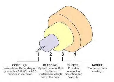
6 2.3 Fiber Optic Cable
Optical fiber cables are the medium of transmission for signals in optical communication systems. A fiber optic cable is made up of three main section. They are the core, cladding, and buffer coating. This is shown in Figure 2.2. The core is in the center of the cable and it consists of silica. It functions as a light emitting part of the fiber and acts as a boundary layer for cables, then the cladding. This cladding consists of pure silica and acts as a guide for light waves to move down the cable. This component is very important because light travels in waves and will shoot out and if these components are not present. This cladding will eventually reflect the core again. For buffers, it is in the center of these three layers and it is composed of acrylic polymers. This buffer shield protects the cladding and core against ultraviolet light and provides rigidity of the cable. This buffer coating is also useful for obtaining data from electromagnetic interference. (Jadhav & Shitole 2013)
[image:21.612.141.528.391.670.2]7
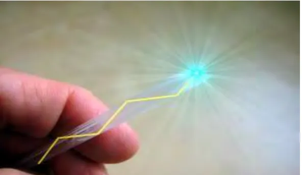
[image:22.612.180.476.260.432.2]Fiber optics is sending signals down hair-thin strands of class or plastic fiber. The light is “guided” down the center of the fiber called the “core”. The core is surrounded by an optical material called the “cladding” that traps the light in the core using an optical technique called “total internal reflection”. The core and cladding are usually made of ultra-pure glass. The fiber is coated with a protective plastic covering called the “primary buffer coating” that protects it from moisture and other damage. More protection is provided by the “cable” which has the fibers and strength members inside an outer covering called a “jacket”. (Amaku et al. 2014)
Figure 2.3: Light pipe; Optical fiber transmits the beam of light down a thin sheet of plastic or glass by making them bounce repeatedly against the wall
2.4 Fiber Optic Sensor
8
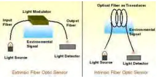
Figure 2.4: Extrinsic and Intrinsic is a Type of Fiber Optic Sensor
The advantages of fiber optic fibers from there. First, the harsh environmental ability against strong EMI (electromagnetic immunity interference), high temperature, chemical corrosion, high pressure and high voltage. Seconds very small size, passive and low power. Third, excellent performance such as high sensitivity and broad bandwidth. Fourth, long-range and final operations, multiple or distributed measurements, are widely used to compensate for their primary weaknesses with high costs and end user uncertainties. (Li et al. 2012)
9
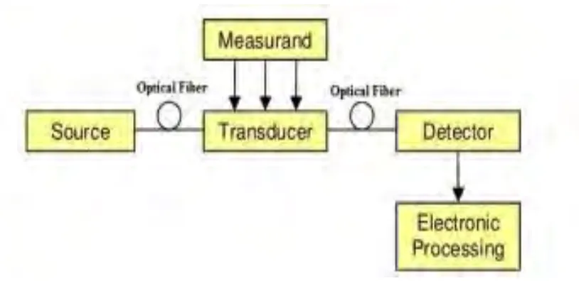
Figure 2.5: The basic components of the sensor system Fiber Optics.
There are advantages of fiber optic sensor including its ability to be light weight, very compact and small. Easy to mount light, low ISI, resistance to electromagnetic interference, high sensitivity, wide bandwidth and environmental resistance making it widely used in different fields. All the features mentioned this the best use of optical fiber as a sensor and a network of optical fiber is very advantageous in the industry for long-term investment. (Ghetia et al. 2013)
2.5 SC Fiber Optic Connector