Ames Laboratory Technical Reports
Ames Laboratory
6-1961
A small scale countercurrent liquid-liquid extractor
Harley A. Wilhelm
Iowa State University
Follow this and additional works at:
http://lib.dr.iastate.edu/ameslab_isreports
Part of the
Chemistry Commons
This Report is brought to you for free and open access by the Ames Laboratory at Iowa State University Digital Repository. It has been accepted for inclusion in Ames Laboratory Technical Reports by an authorized administrator of Iowa State University Digital Repository. For more information, please [email protected].
Recommended Citation
Abstract
Details of design and operation are given for a laboratory-size, 20-stage, multiple-contact, "unlimited-feed", countercurrent-flow, liquid-liquid extractor. The apparatus consists mainly of glass parts that are joined by polyethylene tubing and are mounted in a steel cradle that can rotate on its horizontal axis. The reservoirs for feed liquids are an integral part of the assembly, and proper· rotation of the assembly causes the flow of liquids to, through and from the extractor . Testing and developing of, and small scale production by, extraction systems are conveniently carried out in this extractor. Stagewise and product samples can be readily obtained for study of the extraction behavior of the components of a liquid-liquid system.
Disciplines Chemistry
A SMALL SCALE COUNTERCURRENT LIQUID-LIQUID EXTRACTOR
by
Chemistry (UC-4)
TID 4500, December 15, 1960
UNITED STATES ATOMIC ENERGY COMMISSION
Research and Development Report
A SMALL SCALE COUNTERCURRENT
LIQUID-LIQUID EXTRACTOR
by
Harley A. Wilhelm
June 1961
Ames Laboratory at
' Iowa State University of Science and Technology F. H. Spedding, Director
2 IS-309
This report is distributed according to the category Chemistry (UC-4) as listed in TID-4500, December 15, 1960.
Legal Notice
This x;eport was prepared as an account of Government sponsored work. Neither the United States, nor the Commission, nor any person acting on behalf of the Commission:
A. Makes any warranty of representation, express or implied, with respect to the accuracy, completeness, or usefulness of the information contained in this report, or that the use of any information, apparatus, method, or process disclosed in this report may not infringe privately owned rights; or
B. Assumes any liabilities with respect to the use of, or for damages resulting from the use of any information, apparatus, method, or process disclosed in this report.
As used in the above, "person acting on behalf of the Commission" includes any employee or contractor of the Commission, or employee of such contractor, to the extent that such employee or contractor of the Commission, or employee of such contractor prepares, dis-seminates, or provides access to, any information pursuant to his employment or contract with the Commission, or his employment with such contractor.
Printed in USA. Price
$
0. 75. Available from theCONTENTS Page
ABSTRACT . . . ·. . . 5
INTRODUCTION I I I I I I I I I 4 I I I I I I I I • I I I I ~ I • I • I I I
6
DESIGN AND OPERATION 7
MISCELLANEOUS DETAILS 20
FILLING, STARTING AND ADJUSTING THE EXTRACTOR . . . 25
4
il
A SMALL SCALE COUNTERCURRENT
LIQUID-LIQUID EXTRACTOR
Harley A. Wilhelm
ABSTRACT
Details of design and operation are given for a
laboratory-size, 20-stage, multiple-contact, "unlimited-feed",
countercurrent-flow, liquid-liquid extractor. The apparatus consists mainly of
glass parts that are joined by polyethylene tubing and are mounted
in a steel cradle that can rotate on its horizontal axis. The
reservoirs for feed liquids are an integral part of the assembly,
and proper· rotation of the assembly causes the flow of liquids to, through and from the extractor . . Testing and developing of, and
small scale production by, extraction systems are cbnveniently
carried out in this extractor. Stagewise and product samples
can be readily obtained for study of the extraction behavior of the
6 INTRODUCTION
Countercurrent liquid-liquid extraction is a well established
operation for separation and purification of compounds on laboratory,
pilot plant and large production scales of processing. Each new
extraction problem, however, requires a study to determine
work-able conditions for effecting the desired separation or purification.
Preliminary studies of single stage distribution behaviors of the
components of liquid-liquid systems can give data that are basic to
the development of extraction processes. Later stages in the
development of a practical liquid-liquid extraction process,
how-ever, generally require that tests on the variables in the conditions
of operation also be made with manipulations that simulate those of
the multi-stage equipment to be employed in processing. Proper
equipment for these tests may not only facilitate the derivation of
conditions for laboratory or large scale processing but may also make
it possible to readily obtain data that are basl.c to an understanding of
the extraction mechanism.· This article presents details on the
con-struction and operation of small scale,20-stage,
multiple--contact,counter-current-flow extractor in which such tests can be conveniently made.
Separation and purification of metals through liquid-liquid
extrac-tion of their compounds have received considerable attention and
extraction systems with water and an organic liquid as the relatively
immiscible solvents between which two or more metals as compounds
in a mixture may differentially distribute. A number of such metal
separation systems have been developed in this laboratory employing
equipment of the general type presented here. The extractor described
in detail in this article, however, has a number of improvements
over earlier designs. Although the work here on liquid-liquid extrac- .
tion has been essentially limited to studies of metal separation by
such aqueous -organic systems, it appears that applications to other
problems in the broader field of liquid-liquid, or solvent, extraction
are entirely within the possibilities of the apparatus described in this
report.
DESIGN AND OPERATION
The extractor presented here consists essentially of an orderly
assembly of feeder systems, mixer-settler chambers, interstage
transfer bulbs and connection tubes all made of glass with joints of
polyethylene or other practically inert flexible tubing. The connections
between the parts of this assembly may be so arranged as to give
countercurrent flow of the two liquid phases. This extractor assembly
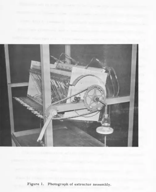
(see Fig. 1) is mounted in an open structure steel cradle consisting
essentially of two steel end plates connected by four lengths of angle
8
a steel framework. The feeding of liquids to the extractor, the
multi-stage extraction and the delivery of product solutions from
the extractor are performed through rotation of the cradle and its
extractor assembly on the horizontal axis. Since these operations
take place repeatedly as rotations of the cradle are continued, the
extractor may be referred to as of the "unlimited feed" type.
Reservoir tarlks containing the liquids to be fed to the extractor
at the desired stages are mounted along the axis of rotation of the
cradle and are parts of the assembly. The two end shafts of the
extractor cradle are hollow and they can, therefore, accommodate
coaxial glass tubes for delivery of product solutions from the
extrac-tor and through glass sleeve joints to stationary receivers. A
sprocket wheel fixed on one of these end shafts enables rotary motion
to be imparted to the cradle by means of a hand-crank operated chain
drive. Feeding of liquids to the extractor, mixing and settling and
countercurrent flow of the phases in the extractor and delivery of
the product solutions from the extractor are, then, effected through
proper manipulation of the hand crank.
The performance of this laboratory extractor si~ulates that
of a continuous countercurrent-flow vertical extraction column.
Extractors that have some physical resemblances to the one presented
10
by von Met:z:sch, ( 3) by Ver:z:ele and
A~derweireldt(
4)
and by Wilhelmand Foos. (S, 6) The apparatus developed by Craig and that developed
by Lathe and Ruthven were, however, designed to move only one of the liquid phases in a stagewise manner; so these extractors, referred to as "limited feed" type, operate on essentially single batches rather than on continued additions of feed. All of the extractors considered here have a common feature in that they depend for their operation on repetition of a sequence of mixing, settling and separate flow of the phases in each stage. Simultaneous operation of a number of stages through this sequence of events gives, through proper connections, effectively progressive stagewise flow.
an extraction process approaches steady-state operation, any such
changes in volumes of the portions of the phases in the various
stages will develop somewhat gradually. Should the volume change
for the more dense phase become such that the position of the inter-·
face is moved significantly, then the tube opening for carrying away
the less dense phase in extractors of the type being considered may
need repositioning. The extractor described in detail here has a
design that permits adjustment of the positions of these openings.
Consequently this extractor has broader adaptability in liquid-liquid
extraction studies and operations than those described by Craig, by
von Metzsch and by Verzele and Alderweireldt which do not provide
for such adjustments. Also the extractor of Lathe and Ruthven,
although quite different in design, lacks the broader adaptability.
Two main features of this extractor that differ from those of
one extractor presented earlier from this laboratory( 6 ) are:
1.) Data can readily be obtained.from all of the stages and not from
just the alternate stages. 2.) The feeders and their supply tanks
are conveniently mounted in the rotating assembly as an integral
part of the flow system of the extractor. This last feature appears
also to be a decided improvement over feeder systems used in any
of the previously reported laboratory extractors that operate on
12
The present design has a number of improvements over that of
a similar extractor reported earlier. ( 5 ) The extractor is, in the
main, an orderly side-by-side arrangement of 20 units; each unit
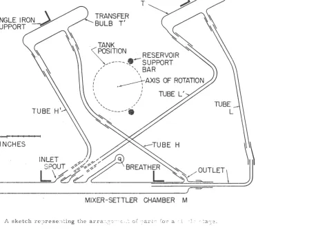
corresponding to a single stage such as that sketched in Fig. 2.
The operation of this extractor may be described by reference to
this sketch. Assume that portions of the two immiscible liquid
phases, differing in density, are in the mixer-settler chamber M.
The two liquids are mixed by causing them to flow rapidly from end
to end in this chamber. An oscillatory motion of this unit about
its axis of rotation, between about +20
°
and -20°
from the horizontalposition represented in Fig. 2, will generally give proper agitation.
After adequate mixing, chamber M is then held at a nearly horizontal
position to permit settling of the liquid phases. The unit is then
turned slowly clockwise through about 90° and as the mixer-settler
chamber goes to a vertical position the light liquid flows out through
tube L toward the inter stage transfer bulb T. It is to be noted here
that the position of the extension of tube L is adjustable within chamber
M so that the separation of the liquids at the liquid-liquid interface
can be properly accommodated. Further rotation of the unit in the
clockwise direction to the 180° position permits the heavier liquid
INLET
/'
/ ' /
---==-=...__~
e1"
e"'
L
w
~UTLET
\
r=='
:--·
MIXER-SETTLER
CHAMBER
M
[image:16.594.136.660.92.509.2]14
At this point, 180 ° clockwise from the starting position, the portions
of the two phases are separated and are in their respective
inter-stage transfer bulbs.
The dashed sections of tube H' and tube L' in Fig. 2 indicate
that in the complete ass'embly these tubes are not actually connected
to inlet spouts on the mixer-settler chamber shown but to spouts of
similar chambers on either side of this chamber. Further clockwise
rotation of the unit, then, allows the separated liquids to flow from
the transfer bulbs to mixer-settler chambers M+ 1 and M-1 that are
juxtaposed to chamber M in the total assembly. This completes one
cycle of operation for a single stage. For the entire assembly,
simi-lar patterns of flow are simultaneously effected for all of the stages.
On each successive cycle during continued operation, then, the
mixing-settling-flow sequences for all of the 20 stages take place
concurrently. The net result is countercurrent flow with the more
dense and less dense liquid phases being delivered from stages at
opposite ends of the extractor to stationary receivers.
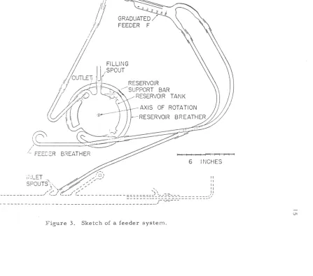
The feeding of liquids to the extractor is essentially automatic,
and an explanation of the feeder system may be facilitated by reference
to Fig. 3. Here a mixer-settler chamber is shown by dashed lines
in order to clarify the arrangement of the feeder unit with respect to
the extractor system. The axis of rotation, the reservoir support
~
·
~~~TTS'\;
~;;'--~)
::
~)~,;/,.--:./ ,', II
,..--- ____ .,/ t~_..,1
c __
~'( ____
~__________________
)
\. __
-:,='-- _ ) } [image:18.595.148.627.64.467.2]==~~)=~~::~---
,
-
---
---~~~~~~~~~f-=-=-~-==-=-===
== ::::::::::-/
Figure 3. Sketch of a feeder system.
16
indicated in Fig 2. Liquid from the cylindrical reservoir tank
of Fig. 3 flows into and floods the graduated feeder F at a point
near or shortly beyond the 180° of clockwise rotation in
the operation cycle described above. Continuation of this
clock-wise rotation causes excess liquid in the tubes connected to the
feeder to flow back to the reservoir. When this rotation is such
that the liquid level is within the upper enlarged tube section of
feeder F, a short quick rotary movement is imparted. to the
assembly to bring the graduated section of the feeder to a vertical
· position. This position is held until the excess liquid has flowed
from the graduated section of the feeder. By this manipulation a
measured volume of liquid is retained for delivery to the extractor
on completion of the cycle. It is to be noted that the position of
the return flow tube in the graduated feeder is adjustable; it is the
position of this tube that determines the volume of liquid delivered
by the feeder.
For this extractor which simulates a vertical extraction column
with countercurrent flow, three such feeder systems ar.e generally
adequate. One feeder may introduce organic solvent at one end of
the extractor, one may introduce aqueous scrub at the other end and
another may introduce feed solution at some intermediate stage. So
taken from three reservoirs and delivered simultaneously to the
extractor at the selected stages. The net result of the over-all
operation of repeated cycling is then continued output of product
liquids through countercurrent flow maintained by continued feed
from the reservoirs.
In order to insure proper flow of the liquid phases during the
cycle it is essential that adequate breathers, or air vents, be
provided in the equipment. The breather for the mixer-settler
chamber is shown in Fig. 2 as a bulb approximately 20
milli-meters in diameter with the breather hole in one side. The breather
for the graduated feeder is shown in Fig. 3 as merely a long curved
tube that is bent sharply at the open en .. The breather system for
the reservoir tank is a combination of four such tubes, each of which
almost completely encircles the tank. A constriction at about the
mid point of each of these fot\ breather tubes helps to restrict the
rate of flow of liquid in this breather system. Although the
connec-tions of these four circular breathers to the tank are positioned as
indicated in Fig. 3' at about 90
°
intervals around the cylindrical tankaxis, only one of these breathers is represented in this figure.
Figure 4 is a more detailed sketch of the reservoir with the tank,
breathers, filling spout and outlet shown in perspective.
In the operation of this extractor the flow pattern is such
SPOUT
BREATHERS
·• ' -\
Figure 4. Sketch showing, in perspective, some details of a feeder system reservoir.
[image:21.592.36.745.19.567.2]in essentially one direction by one stage only on each successive
cycle until it is discharged from an end stage. It is obvious that
since the two phases move countercurrently on each cycle of
operation there are portions of the light phase and heavy phase
that do not contact one another. Alternate portions of the light
phase will contact only alternate portions of the heavy phase.
However, each portion of either phase contacts a portion of the
other phase in each of the stages on its way to discharge. Ineffect
then, this extractor is equivalent to two extractors of a type
de-scribed earlier(b). working in parallel but offset by one stage. The
net result of a stagewise analysis then would correspond to an
analysis of a complete series of stages in a countercurrent-flow
liquid-liquid extraction column.
The capacities and dimensions of the parts of this extractor
were chosen for the particular laboratory scale of operation desired.
Each mixer-settler chamber will conveniently accommodate a volume
of about 60 milliliters of the combined liquid phases per cycle
through the mixing, settling and separation operations. The same
general design could readily be employed in construction of an
extra,c-tor of much greater capacity. Smaller scale equipment of this design
could be constructed; however, when the sizes of parts are so small
that the proper flow of liquids is restricted through surface tension
20
The main body of each of the mixer-settler chambers (refer to
Fig. 2) for the extractor being described is 18 inches in length and
was made from 25-millimeter diameter glass tubing. The transfer
bulbs are 6. 5 inches in length and were made from 30-millimeter
tubing. All spouts and connecting glass tubing indicated in Fig. 2
are 8 millimeter size except for a 13-millimeter spout and its
7-millimeter insert tube that are parts of the adjustable connection at
the delivery end of the mixer-settler chamber.
The reservoir tank in the feeder system of Fig. 3 is a cylinder
about 4. 5 inches in diameter and 9. 5 inches 'in length. It has an
operating capacity of about two liters of liquid. The filling spout and
the breathers to this tank were made from 10-millimeter tubing. The
main body of the graduated feeder (graduated in milliliters) was made
from 25-millimeter glass and is about 5.. 5 inches in length; all
\
spouts sealed to the body of this feeder are of 10-millimeter glass
tubing.
MISCELLANEOUS DETAILS
The cradle that supports the glass extractor assembly (see Fig. 1)
consists essentially of two 14-inch by 17-inch by one-quarter-inch thick
steel end plates connected by four 43-inch long sections of one-inch
angle iron welded in position. The relative posith,ns and tilts o.f these
in bolting the glass parts to the angle -iron supports; plastic separators
prevent contact of the glass and metal. Another section of one -inch angle iron that is bolted to the end plates is used to support the graduated
feeder.s as shown in Fig. 1. The two reservoir support bars indicated
in Fig. 3 are removable one-half-inch diameter steel rods that are parallel to the axis of rotation and are supported by the end plates. The tanks are strapped to these two bars. The hollow end shafts are one-half-inch inside diameter and were made from one-inch diameter steel rod. The end plates of the cradle have mounting hubs for the hollow end shafts that provide the means for support of the cradle in bearings
(pillow blocks) mounted on members of the over-all steel framework of the extractor.
This steel framework (see Fig. 5) is constructed of two-inch angle iron and is 53 inches long by 34 inches wide and, as mounted on four four-inch c'asters, stands 60 inches high. The extractor assembly is covered by a sheet of three-quarter-inch thick plywood that is
mounted on top of this framework. For convenience in charging the reservoir tanks, holes about one inch in diameter are drilled through this plywood at points above the filling spouts of the reservoir tanks. A stainless steel pan for catching liquids from washing or from any
leaks that may develop is supported in the f~amework attd below the
22
[image:25.591.23.534.61.715.2]A number of other miscellaneous details in the design and
construction of the particular extractor contribute to facilitating
its operation. The small sprocket to which the hand crank is
attached (see Fig. 1) is specially made with half as many sprockets
as the larger wheel that is secured to one end shaft of the cradle.
On repeated cycling during an extraction operation, mixing and
settling and flow of liquids recur then at certain positions of the
hand crank. The position of the small sprocket wheel axle can be
adjusted on the steel framework in order to properly tighten the
chain of the drive;
A circular plate that is secured stationary to the bearing
support and mounted back of the larger sprocket wheel has a number
of holes drilled on a circle near its circumference. Two pins that
are mounted on this sprocket wheel can be inserted into these
J:loles to lock the cradle in position. Since these two pins are separated
by a distance equal to that for nine and one-half holes on the circular
plate, the number of possible lock positions are double the number of
holes in the plate. Another small pin on the back side of the large
sprocket wheel and near its chain track activates the rotation, or
'
.,
cycle,counter that is secured to the framework.
In moving the extractor through its 360 ° cycle there are positions
of oscillation, hold, slow movement, intermediate movement and
24
the proper sequence; however, a two-inch-wide steel band that is
bolted to the end plate of the cradle near the chain drive is color
coded for proper manipulation. A pointer mounted on the
frame-work extends to this color coded band; this combination can help
keep the operator informed as to the particular manipulation being
approached.
If the two inlet spouts on each mixer-settler chamber were in
the same plane as indicated by the sketch in Fig. 2, a congestion
of tubes, connections and breathers would be experienced on each
mixer-settler nea,r these spouts. In actual construction of a
mixer-;
settler chamber, however, these spouts are attached so that they
are spread by about
zoo
with respect to the circular cross ...sections of this chamber. This arrangement not only avoids the
congestion but points these inlet spouts more nearly in the direction
of the tubes leaqing from their respective transfer bulbs {see Fig. 5).
Polyethylene tubing connections generally can be forced over
slightly larger glass tubing more readily if they are near the
tempera-ture of boiling water when installed. Certain connections, especially
those between two greatly different sizes of glass such as at the outlet
end of the mixer-settler chamber of Fig. 2, may require pre-shaping.
One method for forming such preshaped connectors is to select
polyethylene tubing of the proper size to fit the smaller of the two
sizes of glass, heat a short section at one end of this polyethylene
tubing in boiling water and then force it over a lubricated steel
form of about the same size as the larger glass. On cooling,
the polyethylene retains the size of the .steel form. Cutting the
polyet~ylene connector to the proper length, inserting in place
and reheating with a steam jet can give the proper fit. A small
amount of a lubricant such as a silicone grease may be needed
between the glass and polyethylene for the adjustable connections.
FILLING, STARTING AND ADJUSTING THE EXTRACTOR
Starting an ex;traction with this equipme:n.t, as well as with
arty other extractor, requires that some workable plan be followed.
One systematic procedure that may be used with the extractor
described here will be given in some detail. Assume that the plan
of the extraction is to employ an organic (less dense) liquid that
is to enter at on~ end of the extractor, an aqueous scrub that is to
be introduced at the stage at the opposite end of the extractor and
an aqueous feed, that is a solution of two :r:naterials to be separated,
is to be fed to the extractor at some intermediate stage.
Inter-stage connections are such that the aqueous phase and organic phase
move stagewise in a countercurrent fashion through the extractor.
The adjustable tubes in all of the mixer-settler chambers are
set so that their open ends (see Fig. 2) will be well above the estimated
26
vertical position where the separations of phases occur on the first
cycle. For this preliminary adjustment the open ends of these tubes
could be set to be above the calculated levels for the combined phases
in their respective stages but they must not be set so as to be below
the liquid-liquid interfaces.
The graduated feeders are next adjusted to deliver the desired
volumes of the three liquids to the extractor. Connections are made
between the three feeders and the selected stages. The three
reservoir tanks are then charged with their specified liquids. To
do this, the cradle is locked so as to hold the feeder units in a
position near that represented by Fig. 3. The extended stems of
three funnels are passed through the holes in the plywood cover of
the extractor and inserted into the filling spouts of the reservoir
tanks. The liquids are then introduced through funnels that are
above the plywood cover. No tank should be filled more than about
80 percent of its total volume, that is, to a level of not greater
than three-fourths on the vertical diameter of the tank cylinder.
Filling to much above this level could cause interference in the
tank breathing and liquid flow. The funnels are removed and the
filling spouts to the tanks are then plugged.
The extractor cradle assembly is next rotated clockwise about
45° where the position· of the mixer-settler chambers is still
,,
to the horizontal as viewed from the sprocket end. The cradle
is then locked with the chambers in this posit~on for the preliminary
charging.
The plugs of the spouts (see spoutS, Fig. 2) are removed and volumes of aqueous scrub equivalent to the total volume of aqueous phase to be treated in each of the stages per cycle of operation are placed in the respective chambers through their spouts. Those stages that will operate with both aqueous scrub and aqueous feed will receive at this time a volume of aqueous scrub equivalent to the volume of both aqueous liquids. Next a volume of organic, roughly equal to the planned volume to enter the extractor on each cycle, is introduced into each of the mixer-settler chambers. The plugs to the spouts are inserted and the cradle rotated counterclock-wise to the position corresponding to that of Fig. 2. Receiving flasks are then placed at both ends of the cradle, as indicated by
Fig. 5, for deliveries from the extractor. The extractor is now properly charged and ready for starting through the first cycle of operation.
The mixing of the portions of the two phases in all of the 20 stages is accomplished simultaneously by the oscillatory motion
described earlier. Twenty to thirty seconds of good mixing of the
28
equilibrium distribution conditions for many systems. At the end
of a mixing operation, any liquid that may be in the outlet tubes of
the mixer-settler chambers should be allowed to drain back; then
these chambers are moved slowly to near the horizontal position,
indicated in Fig. 2, for settling.
When the phase settling is essentially complete in all
stages, the cradle is rotated clockwise (very slowly at first to
minimize remixing) for about 90
°
to attain the position where themixer-settler chambers stand vertically. The adjustable outlet
tube in each of th~ 20 chambers is then positioned where its open
end stands about one-half-inch above the liquid-liquid interface
in the chamber. In the next 90 ° of clockwise rotation that continues
in this cycle, a considerable amount of the organic phase in each
stage is, then, ·allowed to flow with the aqueous phase. The filling
of the graduated. feeders takes place during the third 90
°
ofclock-wise rotation and the procedure as described above for this operation
is followed. Another 90"' of this rotation completes the first cycle.
At the proper point in subsequent cycles the position of the tube
opening of the adjustable outlet in each mixer-settler is inspected
and corrected if needed in order to insure that none of the heavier,
aqueous phase will flow with the organic phase to the next stage. As
of these outlets are moved nearer to, but always maintained above,
the liquid-liquid interfaces. This condition allows a small amount
of the organic phase in each stage to go with the aqueous phase to
the next stage. There, this amount of organic is combined with the
regular flow to that stage and on the next cycle returns to the stage
from which it came. In effect, then, a small amount of backmixing
of the organic takes place. The amount of this backmixing at each
stage is determined by the position of the adjustable outlet tube with
respect to the liquid-liquid interface at the separation position in the
cycle. As a final adjustment, a safe position for the open end of the
outlet tube in this extractor is about three millimeters above the
interface, The backmixing of the organic phase will then in general
be relatively small, but it is essential in order to insure that
back-mixing of the aqueous phase, which could apparently throw subsequent
stages out of adjustment, does not take place. It should be noted
that there is no bypassing of stages by either phase in the operation
of this extractor.
USE OF THE EXTRACTOR
After charging the extractor as described above, a number of
cycles of operation will be required before any detectable effect of
the feed material from the solution that enters at an intermediate
30
extractor. After this point is reached for a discharge liquid, how-ever, the amount of the product delivered per cycle at that end of
the extractor may increase rather abruptly. As the cycles are
continued the amounts of products as well as their purities will
tend to level off at values determined by the conditions of the
extrac-tion. Wheh the point of essentially no change in the products is
reached on repeated operation, the system may be considered as operating at steady state.
Since the reservoir tank in each feeder system for the particular
size of equipment described here will accommodate about two liters
of liquid, one or two chargings of these tanks can in general supply
liquids for enough cycles of operation to bring the extraction system
to essentially s~eady state for the condition selected. However, if
the major conditions of operation are shifted as the cycles progress,
as might be expected in the development phase of an extraction process,
then further charging of some tanks may be required before steady state is attained with the final conditions. Assuming equilibrium in
the mixing, the major conditions of operation are constitution of the
liquids, feeder-stage connections and relative flow rates, or flow ratios, of the liquids to the extractor. The behavior of the system in
the extractor and analytical data on the product solutions are generally
.:
small amounts of materials, however, are usually adequate in the
use of this extractor for testing and developing extraction conditions for a potential liquid-liquid system.
This small extractor is also convenient to use where the supply of material has limitation considerations or where only a small
amount of product is desired . . Continued operation, however, yields
more product; and extractors of this design but with larger capacity
parts can be used to produce rather significant amount of products. (6 )
The small extractor can usually supply adequate amounts of samples
for making, by ordinary analytical procedures, a number of
determina-tions on the constituents of interest in the liquids.
At the completion of an extraction test it is possible to get detailed stagewise data on the liquid-liquid system. Volumes of the phases and concentrations of the species in each phase in each of the stages constitute data that may be obtained and used in interpretation of the
behavior of the constituents in the over-all extraction process. If
stagewise data are to be obtained, it is essential that the stages be
sampled only after thorough mixing of the liquids that are in the
mixer-settler chambers at the end of the ~ast complete cycle of operation .
An extractor of the design described here allows an experiment
to be interrupted and then' resumed at the operator's convenience
32
periods of unattention by the operator are necessary during an
extraction experiment that may intermittently extend for a number
of days. Only in case the liquid-liquid system itself presents a
time dependent condition of instability may the convenience of
intermittent operation not be fully realized.
For experimental work with the extractor, hand operation has
been quite satisfactory; however, if such an extractor were to be
employed in somewhat routine productions, a programmed motorized
drive that would move the extractor assembly through the sequence
LITERATURE CITED
1. Craig, L. C., Anal. Chern. ~· 1346 (1950).
2. Lathe, G. H. and Ruthven, C. R. J., Biochem. J. 49, 540 (1951).
3. von Metzsch, Friedrick-August, Chern. Ing. Tech. ~· 262 (1959).
4. Verzele, M. and Alderweireldt, F., Nature 174, 702 (1954).
5. Wilhelm, H. A. and Foos, R. A., U. S. Atomic Energy Comm.
Rept. ISC-458 (Sept. 3, 1954).
6. Wilhelm, H. A. and Foos, R. A., Ind. &: Eng. Chern. 51, 633