International Journal of Innovative Technology and Exploring Engineering (IJITEE) ISSN: 2278-3075,Volume-8, Issue-10, August 2019
Abstract: This article deals with the various designs of a novel compact microstrip fed UWB antenna to investigate the corresponding return losses of different structures. The dimension of the designed antenna is 33 x 19 x 1.9 mm3 with FR4
substrate and it can be operated from 2.846 - 11.7458 GHz. The effects of varying the structure of antenna are to exhibit the investigation of corresponding return losses. Different structures of antenna are simulated in Ansoft HFSS simulator. The results of return losses and radiation patterns are explored with the ultra wide band (UWB) rectangular Stair slot antenna. The modified structure of antenna shows the minimized return loss with an enhanced bandwidth that satisfies good UWB characteristics. Antenna performance can also be explored from the radiation behavior of the antenna which is relatively omni-directional pattern for rectangular Stair slot antenna
Keywords: UWB, rectangular stair slot antenna, return loss, Bandwidth enhancement, radiation pattern, microwave imaging.
I. INTRODUCTION
In recent, UWB is a challenging technology in the field of RF communications. It is most popular in the wideband antenna system. The requirement of UWB antenna is mainly faster transmission in wireless medium, simple structure, good resolution, low profile, high security and low fabrication cost. This type of antenna can be obtained by modifying various shapes like square, circular, triangular, rectangular, pentagonal, elliptical, hexagonal etc. The designed antenna should be small size and stable to the overall frequency band. The UWB bandwidth enhancement is achieved by introducing several step cuts of the antenna. N. S. Hassaine et. al [1] have suggested an enhanced bandwidth for UWB Bowtie slot antenna. Importance of changing the structure of antenna on its working with advantages and bandwidth are explained. The return losses and radiation patterns are simulated from designed antenna are elaborated. Final antenna design satisfies UWB characteristics and has surpassed the necessity of bandwidth. Khodadad Halili et. al [2] have proposed a circular cylindrical microwave imaging system uses a UWB printed monopole antenna. The fractional bandwidth of 2.91–14.72 GHz is obtained with a square patch antenna of a modified ground plane. More impedance bandwidth can be achieved at the higher band by modifying the antenna structure along with the ground plane.
Revised Manuscript Received on August 20, 2019.
A. Amir Anton Jone, Department of ECE, Karunya Institute of Technology and Sciences, Coimbatore - 641114, India
T. Anita Jones Mary, Department of ECE, Karunya Institute of Technology and Sciences, Coimbatore - 641114, India
The designed microstrip patch produces improved field distribution in omni-direction. Magthoom Fouzia Y and K. M. Jeyanthi [3] a small Bowtie antenna with the rounded edge is selected for imaging techniques is presented. It is designed using FR4 substrate to operate in 5.8 GHz. It is able to maintain the better performance with the return loss of -29.62 dB at gain of 6.2 dB over an entire frequency ranges. Suresh Subramanian et. al. [4] has suggested the modified antenna 27 * 29 * 1.6 mm3 with FR4 substrate suitable for UWB applications. The obtained results are return loss < -10 dB and VSWR ≤ 2 with its operating frequency between 3 GHz and 15 GHz shows good performance of the antenna. A. K. Gautam et. al. [5] has presented the optimized hexagonal shaped antenna in terms of height and size. In order to save the space effectively, the ground plane is vertically extended towards the radiator. Over a bandwidth of 2.71 – 12.6 GHz the prototype antenna 25 * 23 * 1.6 mm3 attains the better impedance matching and the steady radiation pattern. Santanu Mondal, and Partha P. Sarkar [6] the planar hexagonal antenna fed by co-planar waveguide has been preferred for UWB applications. Enhancing the impedance bandwidth can be made possible by introducing semi- circular base to upper and lower side of radiator. By top loading the shorting strip to antenna the compactness can be achieved. Antenna radiates in bi-directional pattern in both azimuth and elevation plane.
W. Mazhar et. al. [7] designed antenna of 34 * 36 mm2 with FR4 substrate of front face has rectangular patch with narrow cut and a back end has a partial ground with slot. Antenna is fed by step impedance microstrip feedline of 50 ohms and SMA female connector. Analysis of antenna can be done in both frequency and time domain, satisfies ultra-wideband frequency. The simulated results show the various return losses and patterns of designed antenna.
Suresh Subramanian and K. R. Shankar Kumar [8] have designed portable antenna 27 * 29 * 1.6 mm3 with FR4 substrate is fed by step impedance microstrip line. The simulated antenna is fabricated and measured. The antenna impedance bandwidth (S11 < -10 dB) and VSWR ≤ 2 is operating from 3 – 15 GHz which is more suitable for UWB applications.
Aswathy Sam and Amir Anton Jone .A [9] has focused on UWB radar imaging technique. The designed wide slot antenna with an excellent performance is obtained in the band of 3–10.6 GHz. The working of wide slot antenna is more sufficient than other systems or patches. The wide slot antenna has an improved return loss of -34 dB by using fork
A Novel Compact Microstrip UWB Rectangular
Stair Slot Antenna for the Analysis of Return Losses
tuning stub and its bandwidth is also improved to 13%. The wide Slot antenna with compact, low profile and improved 67.6 % of efficiency is best suited for UWB applications [16].
N. Ojaroudi et. al. [10] has presented a novel multi-resonance antenna for medical imaging applications. The modified antenna has a design of square patch, a feed line and ground plane with L-Shaped narrow cuts that provide a wider bandwidth of 2.95–14.27 GHz. Extended resonance can be obtained by modifying a pair of L-Shaped narrow cuts and parasitic structures in ground plane. The designed antenna is symmetry with the frequency band of 10.3 GHz – 14.2 GHz. The final antenna produces acceptable gain and good omni-directional patterns. A. H. M. Z. Alam et. al. [11] the planar rectangular UWB antenna 40 * 40 * 1.6 mm3 is designed with unsymmetrical feed line which plays an vital role in enhancing the antenna bandwidth. It is then also modified as tuning fork shaped antenna to enhance the bandwidth of antenna. The simple configuration easily fabricated antenna satisfies -10 dB return loss from 3.8 GHz to more than 15 GHz. The result shows that antenna could be used for UWB applications.
II. ANTENNA DESIGN
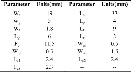
[image:2.595.68.271.432.603.2]The UWB antenna is the prominent component to provide high efficiency to detect the cancerous tissue. The antenna designed in this article is rectangular stair slot shape with 50 ohm impedance matching In order to improve impedance matching, offset feed from the center is used to feed the antennas with a micro strip feed line and the antenna is printed on FR4 substrate.
Fig. A Proposed rectangular stair slot antenna Table. 1 Antenna design parameters Parameter Units(mm) Parameter Units(mm)
Ws 19 Ls 33
Wp 3 Lp 4
Wf 1.8 Lf 9
Lg 6 Lr 2
Fd 11.5 Wu1 0.5
Wu2 0.5 Wu3 1.5
Lu1 2.4 Lu2 2.4
Lu3 2.3 -- --
The challenge is to design UWB antenna with compact size and good performance. The antenna is rectangular step slot that has sustained a variety of changes so as to beat limitations of narrow bandwidth and poor impedance matching. The US Federal communication commission suggested UWB bandwidth of 3.1 to 10.6 GHz. An increase of Stair between feed and antenna allows development of resonance and better adaptation. The length and width of Stair are L1 =L2=2.4, L3=2.3 and W1=W2=0.5, W3= 1.5. The designed wide band antenna has resonated at wider frequency that expands the bandwidth. The simulated return losses for the rectangular Stair slot antenna with the same ground plane is depicted in several Stair:
Step: 1 Introducing center feed (Fd =8.45 mm) for
rectangular monopole radiator to achieve UWB specifications but the matching conditions are poor.
Step:2 The feed (Fd=9.5 mm) is slightly shifted towards
right in order to improve matching conditions and it can be seen that bandwidth is altered in the range of 7.2GHz to 7.9 GHz but the impedance matching conditions are still not satisfied.
Step:3 Near offset feed (Fd =10.5 mm) is introduced to have
proper impedance matching even then the bandwidth is 5.690GHz to 11.800GHz, still it needs enhancing.
Step: 4 Poor impedance matching conditions are slightly
recovered by exact offset feed (Fd=11.5 mm) so that the bandwidth is increasing in the range of 3.321 to 6.000 GHz (offset feed).
Step: 5 Slots are introduced to improve the Bandwidth value
from 3.254 to11.6253 GHz (offset feed with 2 slots)
Step: 6 Initialize the step cutting in the frontline of
microstrip patch to obtain the bandwidth between 3.1729 GHz and 11.775 GHz.
Step: 7 Further one step cut is added to obtain BW from
2.9893 GHz - 11.6911 GHz to improve the impedance matching.
Step: 8 Again two step cuts are added to achieve the good
and maximum BW from 2.8460GHz - 11.7458GHz for the designed rectangular Stair slot shape UWB antenna is proposed.
[image:2.595.54.282.644.770.2]International Journal of Innovative Technology and Exploring Engineering (IJITEE) ISSN: 2278-3075,Volume-8, Issue-10, August 2019
[image:3.595.308.547.54.238.2]Fig. 1 First Antenna Structure without return loss
[image:3.595.58.281.204.381.2]Fig. 2 Second modified antenna structure with return loss of -34.5 dB, -19.99 dB
Fig. 3 Third modified antenna structure with return loss of -10 dB, -24.07 dB
Fig. 4 Fourth modified antenna structure with return loss of -9.99 dB, -27.17 dB
[image:3.595.307.547.238.434.2]Fig. 5 Fifth modified antenna structure with return loss of -10 dB, -9.99 dB
Fig. 6 Sixth modified antenna structure with return loss of -10 dB, -10 dB
[image:3.595.306.546.475.653.2] [image:3.595.54.288.581.756.2]Fig. 8 (Proposed) Eighth modified antenna structure with return loss of -10 dB, -10 dB
In this work, comparative analysis of return losses for rectangular step slot antenna is presented. There are totally eight modified antenna structures, with a slot and step cuts as shown in above figures.
IV. COMPARATIVE ANALYSIS
[image:4.595.53.288.50.227.2]A novel ultra wideband rectangular Stair slot antenna is designed and simulated with a frequency band of 2.846 - 11.7458.ghz. The performance metrics of the different structures of designed antenna can be known by the analysis of different return losses.
Table 2. Comparison of return loss (RL) and frequency band of different antenna structures
Design Stair (feedline)
Frequency
band Impedance Bandwidth (dB) RL
8.45mm (Figure. 1)
Nil Nil Nil
9.5mm (Figure. 2)
7.2-7.9 0.181 -34.15, -19.99 10.5mm
(Figure. 3)
5.692-11.8
0.378 -10.00, -24.07 11.5mm
(Figure. 4)
3.321-6 0.703 -9.99, -27.17 Offset feed +
slot (Figure. 5)
3.254-11.625
0.814 -10.00, -9.99 Offset feed +
slot + step cut (Figure. 6)
3.172- 11.775
0.831 -10.00, -10.00
Offset feed + slots + 2nd step cut (Figure. 7)
2.989-11.691
0.861 -10.00, -10.00
Offset feed + slot + 3rd step cut (Figure. 8)
2.846-11.745
1.131 -10.00, -10.00
The return loss is acceptable only when impedance bandwidth is determined. The range of frequencies where the antenna has good impedance matching that can be satisfied by the return loss of -10dB. An experimental result shows that the U.S FCC proposed UWB concept starts only from fifth antenna structure and provides better matching impedance at next Stair (sixth and seventh modified antenna
structure). Further to achieve the good and maximum bandwidth from 2.8460GHz - 11.7458GHz for the eighth antenna structure is designed (rectangular Stair slot shape UWB antenna).
4.1. Return loss
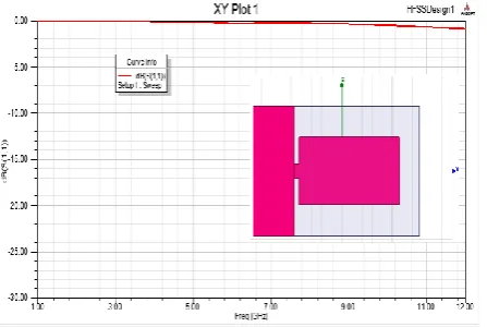
[image:4.595.309.529.207.357.2]S-parameter graph reveals the radiating nature of antenna. The antenna operating in UWB frequency range has its return loss < -10 db. It also offers good impedance matching. The S-parameter is also called as return loss. While cutting a slot on the patch the return loss has been slightly enhanced. The S-parameter bandwidth almost covers the 3.1 GHz to 10.6 GHz UWB frequency range.
Fig. 9 Return loss versus frequency of rectangular stair slot antenna
The return loss values with respect to frequency dip are -20 dB and -14 dB respectively. The simulated and measured return loss graphs are shown in Fig. 5 and it is explained in detail in Step: 1 to Step: 8.
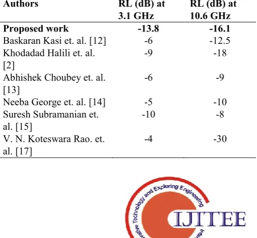
A novel ultra wideband rectangular stair slot (RSS) antenna is designed and simulated with a frequency band of (3.1 – 10.6) GHz. The performance metrics of the designed antenna can be known by the investigation of the antenna parameters like return loss. The proposed work has been compared with existing techniques from the year 2011 - 2017.
Table 3: Comparison of Return Loss (RL) parameter of proposed method with existing methods
Authors RL (dB) at
3.1 GHz
RL (dB) at 10.6 GHz
Proposed work -13.8 -16.1
Baskaran Kasi et. al. [12] -6 -12.5 Khodadad Halili et. al.
[2]
-9 -18
Abhishek Choubey et. al. [13]
-6 -9
Neeba George et. al. [14] -5 -10 Suresh Subramanian et.
al. [15]
-10 -8
V. N. Koteswara Rao. et. al. [17]
[image:4.595.52.286.441.705.2] [image:4.595.302.555.567.801.2]International Journal of Innovative Technology and Exploring Engineering (IJITEE) ISSN: 2278-3075,Volume-8, Issue-10, August 2019
The tabulated result shown in the table 3 that designed antenna has reduced return loss when compared with existing methods for the same band of frequencies.
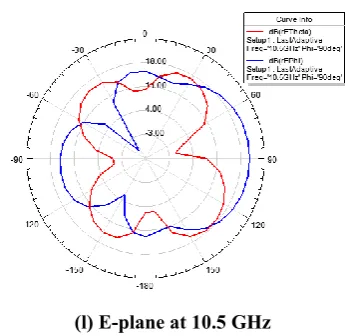
Radiation Pattern
The radiation pattern is one of the most pre-dominant parameter of antenna characteristics. It is the graphical representation of the radiation properties with E-field and H-field pattern. The patterns are usually presented in polar form with a dB strength scale. The pattern is plotted for the range of frequencies 3.5 GHz, 4GHz, 5GHz, 5.8GHz, 8GHz, and 10.5GHz.
(a) H-plane at 3.5 GHz
(b) E-plane at 3.5 GHz
(c) H-plane at 4.0 GHz
(d) E-plane at 4.0 GHz
(e) H-plane at 5.0 GHz
(f) E-plane at 5.0 GHz
(h) E-plane at 5.8 GHz
(i) H-plane at 8.0 GHz
(j) E-plane at 8.0 GHz
(k) H-plane at 10.5 GHz
[image:6.595.340.513.46.214.2](l) E-plane at 10.5 GHz
Fig. 10 2D- Radiation patterns of rectangular stair slot antenna
H-plane radiation pattern look like Omni-directional for rectangular step slot antenna of different frequencies. It is clear that radiation behavior of the antenna is relatively suitable for UWB applications.
V. CONCLUSION
In this paper, different modified structures of UWB antenna are designed to analyze and compare the return losses and radiation pattern. We demonstrate that several step cuts and offset feeds have created an outstanding influence on bandwidth and return loss of the modified antenna. The proposed rectangular Stair slot antenna has obtained wider bandwidth which covers and exceeds the UWB band of 3.1 to 10.6 GHz. The simulated radiation patterns of antenna exhibits an Omni-directional behavior. The modified antenna with reduced return loss is more desirable for UWB characteristics and microwave imaging systems.
REFERENCES
1. N. S. Hassaine, L. Mersad, S. M. Meriah, and F. T. Bendimerad,
“UWB bowtie slot antenna for breast cancer detection”, International Journal of Biomedical and Biological Engineering, vol. 6, No. 11, 2012.
2. K. Halili, M. Ojaroudi, and N. Ojaroudi, “Ultra-wide band monopole
antenna for use in a circular cylindrical microwave imaging system”, Microwave and Optical Technology Letter, vol. 54, pp. 2202-22.5, 2012.
3. Magthoom Fouzia Y and K. M. Jeyanthi, “Design of a novel microstrip
patch antenna for microwave imaging systems”, International Journal of Engineering and Technical research, 119-123, 2014.
4. Suresh Subramanian, B. Sundrambal, and D. Nirmal, “Investigation on
simulation based specific absorption rate in ultra-wide antenna for
breast cancer detection”, IEEE sensors, DOI:
10.1109/JSEN.2018.2875621.
5. Gautam A. K, Richa Chandel, and Binod Kr Kanaujia, “A CPW fed
hexagonal shape monopole-like UWB antenna”, Microwave and Optical Technology Letter, vol, 55, no. 11, 2013.
6. Santanu Mondal, and Partha P. Sarkar, “A novel design of compact
wide hexagonal antenna”, Indian Journal of pure and applied physics, vol. 52, pp. 1-4, 2014.
International Journal of Innovative Technology and Exploring Engineering (IJITEE) ISSN: 2278-3075,Volume-8, Issue-10, August 2019
8. Suresh Subramanian and K.R.Shankar Kumar.: 'Design of a Novel
compact printed Ultrawideband Monopole Microstrip Antenna for Breast Cancer Detection', Journal of medical Imaging and Health Informatics, Dec. 2016, 6, (8), pp 1918-1924.
9. Aswathy Sam, Mr.Amir Anton Jone.A.: 'A Survey on UWB Antennas
Used For Breast Cancer Detection', International Journal of Computer Trends and Technology (IJCTT), 2013 , pp 281-284.
10. Ojaroudi N., Ojaroudi M., and Y. Ebazadeh, “UWB/ Omni-directional
microstrip monopole antenna for microwave imaging applications”, Progress in Electromagnetics Research C, vol. 47, pp. 139-146, 2014. 11. Zahirul Alam, A. H. M. I. Md. Rafiqul, and S. Khan, “Tuning fork
UWB antenna with unsymmetrical feed line”, PIERS Proceedings, 1457-1460, 2012.
12. Baskaran Kasi, Lee Chia Ping, Chandan Kumar Chakrabarty.: 'A
Compact Microstrip Antenna for Ultra Wideband Applications', European Journal of Scientific Research, ISSN 1450-216X Vol.67 No.1 (2011), pp. 45-51.
13. Abhishek Choubey, Rachna Pal.: 'Hexagonal Shaped Ultra Wide Band
Patch Antenna with a Square Fractal in Ground Plane for Breast Cancer Detection', International Journal of Engineering Research & Technology (IJERT), 2012, pp 1-3.
14. Neeba George and B. Lethakumary.: 'A Compact Microstrip Antenna
For Uwb Applications', Microwave And Optical Technology Letters, C 2015 Wiley Periodicals, Inc, 2015.
15. Suresh Subramanian and K.R.Shankar Kumar.: 'Design of a Novel
compact printed Ultrawideband Monopole Microstrip Antenna for Breast Cancer Detection', Journal of medical Imaging and Health Informatics, Dec. 2016, 6, (8), pp 1918-1924.
16. T.Kalaimani, B.Pakiaraj, R.Mohanamurali, “A Compact Coplanar Feed Slotted Antenna for Wireless Applications”, International Innovative Research Journal of Engineering and Technology, v1, i2, 2015.
17. V. N. Koteswara Rao. Devana.: 'A Novel UWB Monopole Antenna