Int. J. Electrochem. Sci., 10 (2015) 5536 - 5547
International Journal of
ELECTROCHEMICAL
SCIENCE
www.electrochemsci.orgPrediction and Supplementation of Reducing Agent to Improve
the Coating Efficiency and Wear Behavior of Electroless Ni-P
Plating
R.Muraliraja, D.Sendilkumar, , DR.R.Elansezhian
Department of Mechanical Engineering, Pondicherry Engineering College, Pondicherry University, India – 604015.
*
E-mail: [email protected]
Received: 1 February 2015 / Accepted: 28 April 2015 / Published: 27 May 2015
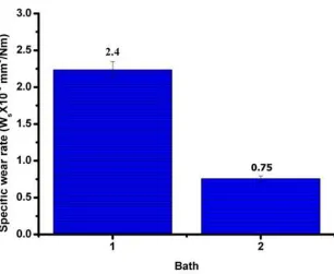
In this work, electroless coating was done on mild steel substrate. It was coated with nickel phosphorous alloy from the electrolyte containing sodium hypophosphite, as reducing agent. So far, the nickel recuperation from the electrolyte was just 25%. Remaining 75% of the nickel particles stay in the electrolyte as waste. To recover more nickel ions from the bath, the amount of reducing agent required during the reaction were predicted and added in the bath to improve the efficiency. The effect of adding excess amount of reducing agent on the coating efficiency, surface structure, phosphorous content in the deposit, wear, adhesion and corrosion behaviour were analysed. The results showed that the coating efficiency was improved to 30%. Since more amount of nickel ions are converted into nickel metal from the bath and deposited on the substrate. The X-Ray diffraction pattern showed that by adding excess reducing agent, a predominated crystalline structure has been obtained due to the presence of more nickel particles in the deposit. Wear resistance of the deposit was improved to 34% when compared to the substrate produced without excess reducing agent.
Keywords: Electroless plating, Reducing agent, Coating efficiency, Morphology, Adhesion, Wear, Corrosion.
1. INTRODUCTION
are widely used in chemical, aerospace, automobile and electronic industries etc. The function of substances used in coating process are a)nickel ions used as a source of nickel metal b)hypophosphite ions are used as reducing agent and it act as an electron donor during reaction c)accelerators activates the reducing agent and increases the deposition rate d)stabilizers are used to prevent breakdown and decomposition of the bath e)pH regulators are used for subsequent pH adjustment during coating process f)wetting agent are added into the electrolyte to increase the wettability of the substrate surface to be coated [2].
In previous publication, efficiency and coating thickness of the coating were optimized by taguchi techniques are studied [3]. Based on the percentage of phosphorus content in the deposit, electroless coating is classified into low, medium and high phosphorous deposit. Phosphorous content in the deposit can be altered by changing the pH in the electrolyte. During coating process, when the pH is maintained at acidic condition (<7), then the deposit contains high phosphorous percentage, at neutral pH (=7) the phosphorus content is medium and at alkaline pH (>7), the phosphorus content in the deposit is low. The deposition rate also mainly relies on the pH in the bath. Various work have been tried to improve the nickel recovery and coating efficiency of the electroless process. Elansezhian et al. reported the influence of two different types of surfactant at various concentrations to improve the efficiency and other properties of the deposit produced by electroless Ni-P plating [4]. Venkatakrishnan et al also tried to improve the properties by secondary reducing agent at the initial stage of the process and his work successfully improved the deposition rate and structures
Table 1. Chemical composition of substrate used.
C wt.%
Mn wt.%
Si wt.%
P wt.%
S wt.%
Fe wt.% 0.20 0.5 0.34 0.045 0.05 Bal.
predicted excess amount of reducing agent was added in the bath at every 10 minute interval to enhance the coating efficiency.
This work, aims to predict the consumption of amount of reducing agent required during the coating process in the bath and supplying it to improve the coating efficiency and properties. So far, researchers have tried only anionic and cationic wetting agents to improve the efficiency and properties of Ni-P coating. In this study, zwitterionic surfactant was introduced as a wetting agent to improve the wear resistance between the deposit and the substrate. The coated substrates were characterized using scanning electron microscope (SEM) and X-ray diffraction (XRD) to study the surface structure of the deposit. Wear resistance of the deposits were analyzed using pin on disc method. Wear tracks on the substrate were also presented and studied using SEM. Adhesion and corrosion characteristics of the coated substrates were also studied.
2. EXPERIMENTAL PROCEDURE AND DETAILS
[image:3.596.106.488.584.701.2]Low carbon steel was used as a substrate material and its chemical composition are represented in Table 1. Substrate material was machined for the required dimensions (9 mm diameter and 30 mm height). Substrates were heat treated at 800°C for 2 hours to relieve the internal stress and then furnace cooled to refine the grain structure. The substrates were surface finished by grinding followed by disc polishing. The substrates were polished with SiC papers 600, 800, 1000 and 2000 grit. Before the coating process, substrates should be cleaned to remove the impurities like oil, grease etc. So, pretreatment has been done on the substrates. The pretreatment procedures are cleaning with acetone, dipping in ethanol for 2 minutes, acid pickling in 10 vol. % of sulfuric acid for 1 minute and finally immersed in prepared electroless bath every step was followed by rinsing with distilled water. The composition of plating bath is presented in Table 2. Temperature of the electrolyte was maintained at 85°C (2°C) and the plating time was restricted to 2 hours. pH of the electrolyte was maintained at 8(alkaline) by adding liquid ammonia solution.
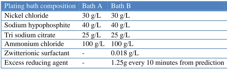
Table 2. Bath parameters
Plating bath composition Bath A Bath B Nickel chloride 30 g/L 30 g/L Sodium hypophosphite 40 g/L 40 g/L Tri sodium citrate 25 g/L 25 g/L Ammonium chloride 100 g/L 100 g/L Zwitterionic surfactant - 0.018 g/L
Excess reducing agent - 1.25g every 10 minutes from prediction
100 %) ( m s c Ni Ni
Ni (1)
Where, Nis is the nickel deposited on the substrate in grams and Nim is the nickel recovered from (beaker + electrolyte + Nis) in grams [7]. Wear behavior of the coated substrates was tested using ducom machine model TR-201 friction and wear monitor with a computer interfaced data acquisition system (Pin on Disc method). Specific wear rate (w) can be determined using the formula below [15].
d L V w
(2)
Where, Δ is the volume loss in mm3, is the load in Newton, and is the sliding distance in meter. The coefficient of friction was calculated using the following formula: Co-efficient of friction (COF)
d Appliedloa
force Frictional
COF (3)
The surface morphology and wear tracks of the electroless nickel coatings were observed by using scanning electron microscope (SEM) with voltage of 15 KV (Hitachi, Model: S-3400N) and elements in the deposits was identified using an EDX attachment. Interfacial adhesion of coated layers to solid surfaces were tested as per VDI 3198 standard, the substrates were analyzed using Rockwell hardness tester with an applied load of 150 kg. Potentiodynamic polarization was executed on an electrochemical analyzer (Princeton Applied Research). The electrolyte used for corrosion analysis was 3.5% sodium chloride and the substrate surface of 1cm2 area was exposed to the electrolyte. Substrates were degreased with acetone, rinsed in deionised water and dried before the corrosion test. The counter electrode used was graphite and saturated calomel electrode (SCE) was used as reference electrode. During the experiment, the open-circuit potential (OCP) was stabilized and the sweep rate was maintained at 1mV/s by immersing the substrate in the electrolyte for a duration of 30min. Current and potential readings were recorded all the while and Tafel plot were produced using the information. The corrosion current density (icorr) was dictated by extrapolating the straight-line segment of the Tafel lines. The corrosion rate (CR) can be determined using the following equation.
d wt Eq I mpy
CR( )0.13 corr . . (4)
where, Eq. wt. is the equivalent weight and d is the density of the nickel metal in g/cm3. Similar method has been followed and reported in the literature [16]. Zwitterionic surfactant [3-(n,n-dimethyl myristyl ammonio) propane sulphonate] was procured for Sigma Aldrich with the purity of ≥99%.
3. RESULT AND DISCUSSION
3.1 Estimation of consumed reducing agent
shown in equation 5 and cathodic reactions that utilize the electron generated in anodic reaction are shown in equation 6, 7 & 8.
V E e H PO H O H PO
H2 2 2 2 32 2 , 00.50 (5) V
E Ni e
Ni22 0, 0 0.25 (6) V
E H e
H 2 , 0.000
2 2 0
(7) V E O H P e H PO
H2 2 2 2 2 , 0 0.50 (8)
The electrons needed to reduce the nickel ions were generated in anodic reaction [17]. The electrons are utilized to convert nickel ion to metallic nickel during reduction reaction. Once the maximum amount of electrons are utilized the reaction speed deceases which leads to reduction of the deposition rate and leave the rest of the nickel ions unutilized in the bath. Finally the unrecovered nickel ions are treated as waste solution. To resolve this issue, the amount of excess reducing agent required to compensate the utilized electrons were calculated from Buttler-Volmer equations (9) and (10). The electroless Ni-P bath is a multi component solution. It consists of nickel source, reducing agent, active surface (substrate), stabilizers and complex agents. The model parameters were developed through robustness co efficient v<1, which make the model (9) & (10) less sensitive to the uncertainties in the equilibrium potentials. The exchange current densities i0n depends on the bath temperature. [18]
) exp(
)
[exp( 1 1 1 1 1 1
1 01
1 i v pk v pk
i a c (9)
) exp(
)
[exp( 2 2 2 2 2 2
2 02
2 i v p k v p k
i a c (10)
Where,
in - Current density (n = 1, ..., 4), A/cm2, i01 - Exchange current density, 17 mA/cm2, i02 - Exchange current density, 2 mA/cm2, ηn - Over potential, ηn = φ - un, V,
φ - Mixed potential, V,
un - Thermodynamic equilibrium potential, V, µn - dimensionless concentration of species, v - Robustness coefficient, 0.1,
k - Temperature voltage, k = F/RT, 1/V, T - Temperature, K,
R - Universal gas constant, 8.3145J/(molK), F - Faraday's constant, 96487 C/mol,
pn - number of exchanged electrons, p2 = 1, p1 = p3 = p4 = 2, αa1 - anodic apparent transfer coefficient, 0.46,
αa2 - anodic apparent transfer coefficient, 0.5,
αcn - cathodic apparent transfer coefficients, (n = 1-4), αan = (1 -αcn).
dW dt
c Q F
i i A
dc 2 1 1f 1f 1
1 ]
2 2
[
(11)
Where,
c1 - hypophosphite concentration c1f - feeding solution concentration
Q1f - hypophosphite dilution rate defined as the ratio between feeding rate and bath volume, 1/s
A - Bath loading defined as the total metal area of plates immersed in the solution per bath volume, cm2/dm3
t - Elapsed time, s
σ1 - hypophosphite model inaccuracy.
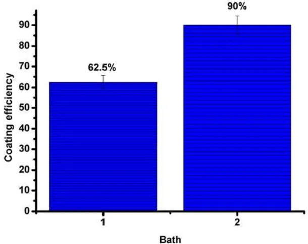
[image:6.596.138.443.332.573.2]3.2 Effect on Coating efficiency:
Figure 1. Coating efficiency of electroless Ni-P coating (1) Bath A (2) Bath B.
current density produced by electrons which resulted in increased coating efficiency of 90% (31% improvement). Once the nickel ions are converted into metallic nickel, attractive force from the catalytic substrate surface absorbs all the nickel metal and it gets coated over the substrate. The recovered nickel particles are utilized properly to improve the coating efficiency of the deposit. The added surfactant provides additional attractive force towards the substrate and leads to increase in the coating efficiency. In previous work, the effects of adding zwitterionic surfactant in the electroless bath were studied. It was reported that the property such as wear, adhesion and coating thickness were improved at the critical micelle concentration of added surfactant [22].
3.3 Effect on structure of the deposits
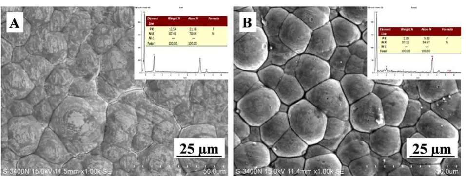
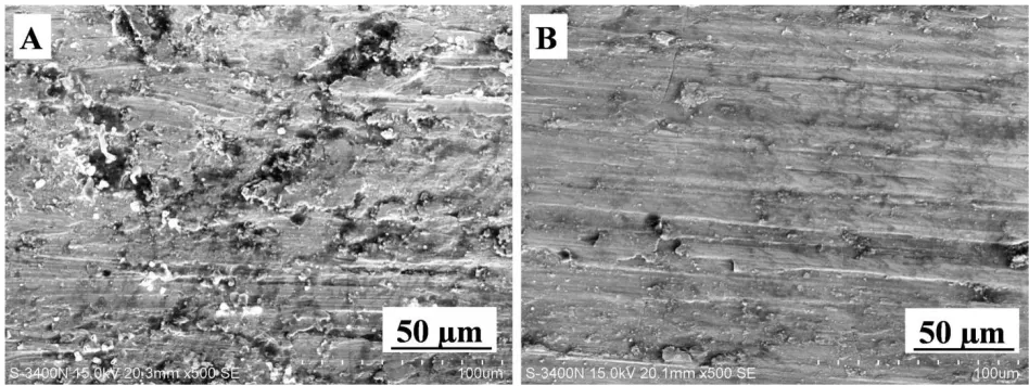
[image:7.596.62.540.256.437.2]Figure 2. SEM micrograph of electroless Ni-P coated substrates (A) Bath A (B) Bath B.
Figure 3. XRD pattern of the coated substrates (A) Bath A (B) Bath B.
[image:7.596.78.507.490.650.2]
boundaries of the nickel particles are filled with the phosphorous. Hence, it gives the smooth surface in SEM micrograph and the smoothness starts decreasing with increase in nickel content in the deposit [23]. But Figure 2(b) reveals the presence of nickel particles which appeared as hemispherical clusters on the substrate surface. EDX analysis of substrates produced by bath B shows less phosphorous content (3%) in the deposit. Reducing agent is responsible for converting Ni ions into Ni particle in the bath. The consumed electrons were constantly replaced by excess RA. Hence, it deposits more Ni particles on the substrate by converting all the available Ni ions in the bath. The pH of the solution is also an important factor affecting both the amount of phosphorous and nickel in the deposit and the rate of hydrogen evolution [24]. The major phases in the coatings of both the bath A&B are identified by X-ray diffraction analysis using Cu Kα radiation. Figure 3 shows the XRD pattern of the coated substrates. The substrate produced from bath A i.e. without excess RA shows the amorphous structure. The reason could be the presence of high phosphorous content in the deposit. Earlier research work reported that the structure of low phosphorous (<7 wt.%P) deposits was crystalline and high phosphorous deposits (>7 wt.%P) showed an amorphous structure with a ‘liquid-like’ disorder of the atoms with a random distribution of phosphorous throughout the coating [7]. Similarly, in this work the structure of deposit with low phosphorus content was found to be crystalline [25].
3.4 Effect on wear, adhesion and corrosion behavior of the coated substrates:
Figure 4. Specific wear rate of electroless Ni-P coated substrates (1) Bath A (2) Bath B.
[image:8.596.136.442.419.670.2]
attractive force from the substrate is not enough to absorb the entire nickel particle to improve the adhesion between the substrate and Ni particle and hence a special type of surfactant is introduced into the electrolyte. The mechanism of wear of the deposit depends on the attractive force that operates between nickel and phosphorous in the deposit and the disk material. Hardened high carbon-high chromium steel was used as disc in wear testing machine. Adhesive wear is portrayed by the exchange of material from one surface to the next, which might later be uprooted as wear debris. It can be enhanced by several factors such as hardness, and the good adhesion property between the deposit and surface of the substrate. Elansezhian et al. explored that the wear rate of the ENi-P coatings created with surfactant is lower when contrasted with the one covered without surfactant [26] . To comprehend the component of wear in the coatings, the wear tracks were examined using SEM. The images are depicted in Figure 5.
Figure 5. SEM micrograph of wear tracks of the substrates (A) Bath A (B) Bath B.
As expected, severe harm happened to the substrates produced without surfactant and reducing agent to the EN bath. The possible reason could be because of their characteristic properties such as ductility, hardness and poor adhesion. SEM images of the deposit prepared without surfactant shows adhesive wear behavior. It reveals that the hardness of the deposit is low, which is the characteristic of the coating produced without surfactant, it increases the development of trash adding to an increment in the contact zone between the tribological pair. Patchy removal of material from the coating and wear debris are noticed in SEM micrograph Figure 5(a). On the other hand, with the addition of surfactant and reducing agent into the bath, it was noticed that the wear tracks get to be smoother on the ragged surface and there was no indication of delamination on the coated surface as evident from Figure 5(b).
[image:9.596.62.536.283.461.2][image:10.596.68.536.172.374.2]
towards the substrate and improved the adhesion of the deposits and the number of radial cracks are very less as shown in Figure 6 (B). Similar results were reported in previous research, surfactant such as SDS and CTAB incorporation in the electroless bath improves the adhesion property of the deposits. Also, it prevents the deposit from getting peeled off and reduces the number of radial cracks after indentation test [27].
Figure 6. SEM image of indentation for adhesion behaviour (A) Bath A (B) Bath B.
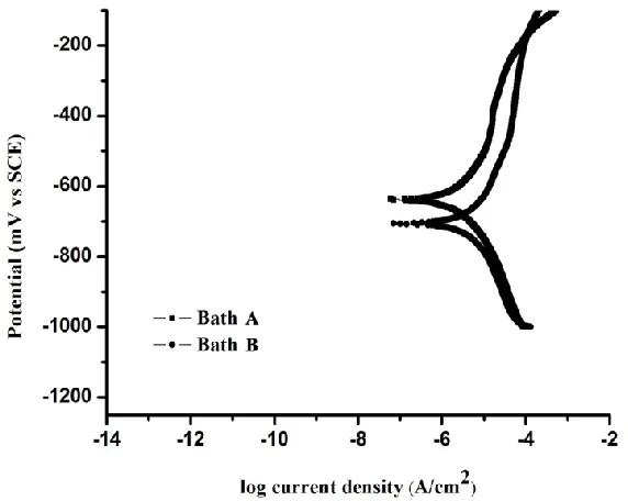
Figure 7. Polarization curves of electroless plated substrates in 3.5 wt. % NaCl aqueous solution.
[image:10.596.142.428.423.651.2]
Table 3. Corrosion analysis of electroless coated substrate in 3.5% sodium chloride solution by potentiodynamic polarization technique
Type of coating Ecorr (mV) Icorr (A/cm2) Corrosion rate (mpy)
Bath A (Ni-P) -639.1 1.207x10⁻⁶ 0.00517
Bath B (Ni-P-Excess reducing agent) -702.9 3.28x10⁻⁶ 0.01454
1.207x10⁻⁶ A/cm2. Element phosphorus present in the deposit was about 13 wt. %, whereas, the deposit produced with excess reducing agent contained only 3 wt. % of phosphorus. The decreased phosphorus content in the deposits reduces the corrosion resistance of the substrates. Phosphorus increases the corrosion potential and the corrosion current decreases, thereby promoting the anodic and cathodic reactions responses amid the consumption process and expands the anodic disintegration of nickel provides prerequisites for concentrating P and thereby for the formation of Ni3P and NixPy stable intermediate compounds on the surface, which goes about as obstruction latent film [28]. This layer thus will hinder the supply of water to the cathode surface, keeps the hydration of nickel, and this is thought to be the first venture to structure solvent Ni ions [29]. Hence, good corrosion resistance resulted for electroless Ni–P than the substrates coated with excess reducing agent. The corrosion rate obtained for bath A, B are 0.00517, 0.01454 mpy respectively.
4. CONCLUSIONS
The ENi-P coating produced with excess reducing agent and zwitterionic surfactant were studied and the following conclusions have been drawn:
The coating efficiency without excess reducing agent was found to be only 62.5%. With the constant addition of the predicted amount of RA, all the Ni ions were converted into Ni particles and coated over the substrate; thereby the coating efficiency was improved to 90%.
The more amount of nickel particle was clearly visible in the substrate coated with excess reducing agent in the SEM micrograph. The structure of ENi-P coated deposit appeared as cauliflower shape. EDX also revealed the presence of more nickel particles (97%) in the deposit. XRD pattern showed the predominant crystalline structure of the deposit coated with excess reducing agent.
The wear resistance of the substrate was significantly increased with addition of surfactant. The wear track becomes smooth on the tested substrate surface and there were no signs of delamination and patchy removal of deposit on the substrate.
ACKNOWLEDGEMENT
Authors would like to thank the central information facility for providing the SEM and XRD facility. Also authors are grateful to Department of Chemistry, Indian Institute of Technology Madras, for providing the corrosion analysis facility.
References
1. G. Mallory and J. Hajdu, American Electroplaters and Surface Finishers Society, (1990) 1. 2. W.Riedel, Finishing publications, (1991) 9.
3. R. Muraliraja, R. Elansezhian, and K. Patterson, Procedia Materials Science 5 (2014) 2478
4. R. Elansezhian, B. Ramamoorthy, and P. Kesavan Nair, Surface and Coatings Technology, 203 (2008) 709.
5. P.G. Venkatakrishnan, European Journal of Scientific Research, 82 (2012) 506.
6. I. Baskaran, T. Narayanan, and A. Stephen, Materials Chemistry and Physics, 99(1) (2006) 117. 7. J. Jappes, B. Ramamoorthy, and P.K. Nair, Journal of Materials Processing Technology, 169(2)
(2005) 308.
8. M. Palaniappa, and S. Seshadri, Wear, 265(5) (2008) 735.
9. J. Balaraju, T.S. Narayanan, and S. Seshadri, Journal of applied electrochemistry,33(9) (2003) 807. 10. R. Idhayachander, and K. Palanivelu, Journal of Chemistry, 7(4) (2010) 1412.
11. L. Zhong, X.-f. Xu, and J.g. Liu, Materials Science and Technology, 2 (2007) 31. 12. W. Lin, X. Xi, and C. Yu, Synthetic Metals, 159(7) (2009) 619.
13. S. Shibli, B. Jabeera, and R. Anupama, Applied Surface Science, 253(3) (2006) 1644. 14. K. Gerasopoulos, Chemical Communications, 46(39) (2010) 7349.
15. T. Bhat, ISRN Tribology, (2013) 256..
16. S. Ranganatha, T. V. Venkatesha, and K. Vathsala, Applied Surface Science 256.24 (2010): 7377.
17. S. Roy, and P. Sahoo, Journal of Coatings, 2013.
18. J. Newman, and W. Tiedemann, AIChE Journal, 21(1) (1975) 25.
19. R. Tenno, K. Kantola, and A. Tenno, Journal of electronic materials, 35(10) (2006) 1825. 20. S.Y.M. Vaghefi, and S.M.M. Vaghefi, Neural Computing and Applications, 20(7) (2011) 1055. 21. J. Van Den Meerakker, Journal of Applied Electrochemistry, 11(3) (1981) 395.
22. R. Muraliraja, and R. Elansezhian, Surface Engineering 30.10 (2014) 752.
23. Y. Huang, and F. Cui, Surface and Coatings Technology, 201(9) (2007) 5416. 24. N. Dirjal, K. Holbrook, and P. Wells, Plating and surface finishing, 85(4) (1998) 74. 25. S.K. Das, and P. Sahoo, Advances in Mechanical Engineering, 2012.
26. R. Elansezhian, B. Ramamoorthy, and P.K. Nair, International Journal of Surface Science and Engineering, 4(3) (2010) 258.
27. R. Elansezhian, B. Ramamoorthy, and P. Kesavan Nair, International Journal of Microstructure and Materials Properties 7.1 (2012) 77.
28. B.W. Zhang, W.Y. Hu, X.Y. Qu, Q.L. Zhang, H. Zhang, Z. Tan, Trans. Inst.Met. Finish. 74 (2) (1996) 69.
29. J. Balaraju, Electrochimica acta 52.3 (2006) 1064.