compound cavity surface emitting semiconductor lasers
.
White Rose Research Online URL for this paper:
http://eprints.whiterose.ac.uk/120568/
Version: Published Version
Article:
Albugami, Naser and Avrutin, Eugene orcid.org/0000-0001-5488-3222 (2017) Dynamic
modelling of electrooptically modulated vertical compound cavity surface emitting
semiconductor lasers. Optical and quantum electronics. 307. pp. 1-19. ISSN 0306-8919
https://doi.org/10.1007/s11082-017-1115-3
[email protected] https://eprints.whiterose.ac.uk/ Reuse
This article is distributed under the terms of the Creative Commons Attribution (CC BY) licence. This licence allows you to distribute, remix, tweak, and build upon the work, even commercially, as long as you credit the authors for the original work. More information and the full terms of the licence here:
https://creativecommons.org/licenses/
Takedown
If you consider content in White Rose Research Online to be in breach of UK law, please notify us by
Dynamic modelling of electrooptically modulated vertical
compound cavity surface emitting semiconductor lasers
N. F. Albugami1 •E. A. Avrutin1
Received: 20 February 2017 / Accepted: 20 July 2017
The Author(s) 2017. This article is an open access publication
Abstract A generalized rate equation model is used to simulate the interrelated amplitude and frequency modulation properties of Electrooptically Modulated Vertical Compound Cavity Surface Emitting Semiconductor Lasers in both large and small signal modulation regimes. It is shown that the photon lifetime in the modulator subcavity provides the ultimate limit for the 3 dB modulation cutoff frequency. It is shown that there is an optimum design (number of periods) of both the intermediate and top multistack reflectors to maximise the large-signal modulation quality.
Keywords Surface-emitting semiconductor lasersElectrooptic modulatorHigh-speed modulationModulation bandwidthCompound cavitySmall-signal
responseLarge-signal response
1 Introduction
Vertical-cavity surface-emitting laser (VCSEL) constructions capable of direct modulation at bit rates in excess of 40 GBit/s have attracted considerable attention for future high speed long- and medium-haul networks. There are two main approaches to realizing this goal. The first one is the improvement in the direct modulation laser performance (Blokhin et al.2009), (Karachinsky et al.2013). For example, it was possible to have an error- free transmission up to 39 and 40 Gbit/bit/s direct modulation working in a temperature up to 100C using oxide-confined 850 nm VCSELs with InGaAlAs based active regions. Another method of improving direct (current) modulation is to modulate two active cav-ities simultaneously and out of phase (Chen et al.2010). Reducing the photon lifetime by
& E. A. Avrutin
shallow surface etching of the top mirror reflectivity can also improve the direct modu-lation (Westbergh et al 2010,2011). The second, fundamentally different, approach to increasing the modulation speed is by using the modulation of thephoton lifetimein the cavity as an alternative to current modulation; see e.g. (Avrutin et al.1993; Germann TD 2012; Panajotov et al.2010; Paraskevopoulos et al.2006; Shchukin et al. 2014; Stanley et al. 1994). Advanced semiconductor lasers involving direct modulation of the photon lifetime promise better dynamic properties than lasers with current modulation because their operating speed is less strongly limited by the electron-photon resonance. Several laser designs to implement this principle have been proposed, and initial measurements are all promising. For example, Germann and co-authors have experimentally demonstrated a modulation bandwidth of 30 Gbit/s with 100 mV and 27 dB electrooptic (EO) modulation changes in the voltage and the optical amplitude for small signal modulation, respectively (Germann TD2012). Large-signal Non-return-to-zero (NRZ) modulation at 40?GBit/s has been confidently and repeatedly demonstrated in (Shchukin et al. 2014). By using a non-absorbing EO modulator in the first known compound VCSEL (Paraskevopoulos et al. 2006), the electrical bandwidth up to 60 GHz and optical bandwidth more than 35 GHz, restricted by the photodetector response, have been achieved. Strain-compensated multiple quantum wells were used in the active gain region in the VCSEL cavity with 960 nm reference frequency and 3–4 nm blue shift in the modulator region. A more recent experimental achievement for photon lifetime modulation was conducted by utilizing the influence of the aperture size on the performance of 850 nm InGaAlAs oxide-confined VCSELs (Bobrov et al.2015). When the aperture size is decreased to an optimum value of 4–6lm and the photon lifetime is reduced from 4 to 1 ps, there is a saturation in the the maximum 3 dB modulation bandwidth at 21 GHz.
subcavity is found to be the ultimate limitation of the modulation speed. A summary of the findings concludes the paper in Sect.4.
2 The design considered and the operating principle
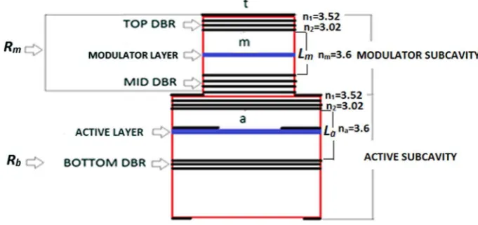
Figure1shows the schematic of a representative Compound Cavity Laser which we used in our analysis. The laser is formed by two subcavities; the top, modulator, subcavity is a passive Fabry–Perot resonator whose reflectivity Rm(t) is modulated via electrooptically
varying the optical properties of a modulator layer contained within the subcavity by applying time-varying reverse bias voltage. In a typical design, the intermediate Dis-tributed Bragg reflector (DBR) has 25–35 periods of two layers of alternating composition, the top DBR consists of 15–25 periods; the resonator thus can be substantially asymmetric. It should be noted that the relatively low Q-factor modulator helps achieving efficient light coupling and low chirp (Paraskevopoulos et al.2006). Throughout the analysis, we con-sider only refractive index modulation (no absorption modulation). Indeed, according to (Shchukin et al.2008), the electrorefraction effect (Miller et al.1985) plays a dominant role in modulatingRm(t) as compared to electroabsorption.
The bottom subcavity is the active one, containing the electrically pumped active layer and terminated by the bottom DBR whose reflectivity is assumed to be very large (about 0.999). Three electric contacts are used in our device to have a good control when changing the current in the active subcavity and the reverse bias voltage for the modulator subcavity as shown in Fig.1.
In a realistic design (see e.g. (Shchukin et al. 2008)), the mesas containing the two subcavities have different lateral diameters; however, as in the previous analysis, we use a purely one-dimensional approach, which is justified because the diameter of the active part of the laser is determined by the current aperture and is thus smaller than the mesa diameter. In this design, we assumed the length confinement factor of 0.0209 and the enhancement factor due to the standing wave pattern of 1.83. As a result, the overall confinement factor in the active subcavity is assumed to be 0.020991.83=0.0382, as in
[image:4.439.47.388.440.600.2]EO modulation is the modulation of the photon lifetime in the active subcavity, determined by the reflectanceRmof modulator subcavity, which is calculated as:
Rm¼rmrm;rm¼ramþ
hamhmarmte j2KmLm
1 rmarmte j2KmLm ð
1Þ
Hererklandhklare complex (and strictly speaking wavelength dependent, though the
dependence is relatively weak) amplitude reflectances and transmittances of multistack DBRs, with the light incidence direction from layer k towards layer l. The layers are denotedk, l=a, m, t, whereais defined as inside the active subcavity,m as inside the modulator subcavity, andtas outside the top layer (see Fig.1). The values are calculated at the wavelengthk. Furthermore, in Eq. (1):
Km¼
2pnm k ¼
nmx
c
is the spatially averaged wave vector in the passive (EO modulator) subcavity,nmbeing the
average refractive index in this subcavity,k=2pc/xthe wavelength in vacuum (xbeing
the optical angular frequency) andcis the speed of light in vacuum. Then, EO variation of the average refractive index (nm) of the modulator subcavity leads to a corresponding
variation in the wave vector K which makes a change to Rmaccording to Eq. (1); this
changes the photon lifetime and the mirror transparency, both of which lead to the mod-ulation of the output light.
Figure2shows the calculated reflectivity versus incident light wavelength for the EO modulator subcavity for a specific case of the GaAs/Al0.2Ga0.8As 80A QW laser operating_ at k=0.9685lm. She reflectivity Rm is very close to one for a broad range of the
wavelengthkbetween 0.9lm and 1.1lm but has a narrow notch, in the case simulated at k&0.9666lm. The inset of Fig.2illustrates how the position of the notch, and thus the
Fig. 2 Calculated Reflectivity versus incident light wavelength for the EO modulator subcavity.Inset: Spectral shape of the reflectance notch with nm=3.620 (solid curve) andnm=3.621 (dashed curve)
reflectance in the relatively narrow range of wavelengths within it, can be modulated by changing the reflective index. It can be seen that the notch can be shifted by 1 nm when the average refractive index is modulated by*10-3. Figure2illustrates the fact that a
sub-stantial variation of the reflectance is possible with the average refractive index varied by about *10-3, but also highlight the narrow wavelength range in which this variation
occurs.
3 The modified rate equation model
3.1 The model
In designing the model, we follow the approach used previously for Distributed Feedback (DFB) lasers (see e.g. Wenzel et al.1996) and for multimode compound cavity lasers (see e.g. Avrutin et al.1999). Namely, the laser cavity is treated as a complex resonator, and a complex eigenfrequency of this resonator is found, which is then used to describe the laser dynamics. She electrooptically modulated VCSEL is very naturally suited for such an approach, because the complex resonator in this case can be defined by considering the active subcavity as a quasi-Fabry–Perot resonator terminated, on one side, by the bottom reflector with a (complex, generally speaking) amplitude reflectance rb and on the other
side, by the EO modulator subcavity treated as a passive, frequency-dependent reflector with a complex reflectance rm(x), where xis the complex eigenfrequency sought. The
value ofrm(x) is calculated from Eq.1with the average wave vector in the form of:
Kmð Þ ¼x
nmþCmDnEO
ð Þx
c ð2Þ
Here DnEO describes the time-dependent correction to the refractive index of the
modulator layer caused by EO modulation.Cmdm
Lm(assuming the modulator layer is thick
enough that the standing wave factor is near one) is the confinement factor of the mod-ulator layer,dm-being the modulator layer thickness andLm, the total physical thickness of the modulator subcavity, including any spacer layers between the modulator layer and the DBRs but not including the penetration into mirrors. The complex eigenfrequency is then found by solving the usual threshold/resonant condition of a Fabry–Perot type cavity (due to the short cavity length, the equation has only one solution):
rmð Þx rbðxÞexp 2 j
naþDna
ð Þx
c þCa g
2
La
¼1 ð3Þ
It is convenient to write this solution in terms of a frequency correctionDx¼x xref,
where the (real) reference frequencyxref is arbitrary but can be conveniently taken, for example, as the position of the reflectance spectrum notch (Fig.2) in either on or off-state. Then, the complex instantaneous frequency correctionDxis defined from a transcendental equation:
Dx¼vg
j
2 Cag 1
La
ln 1
rm xrefþDx
rb
!
Dnaxref
c þ qp
La
naxref
c
" #
Herevgis the group velocity,Lais the geometrical thickness of the active subcavity,Ca
is the confinement factor for the active area, g is the time-dependent gain, na is the
refractive index of the active layer subcavity, averaged over the length in the same way as
nmis averaged over the modulator subcavity. The refractive index varies in time primarily
due to self-phase modulation in the active layer; its time-dependent part can be quantified as:
Dna
c
2xrefCaaHðg gthÞ ð5Þ
whereaHis the Henry linewidth enhancement factor in the active layer andgthis the gain
at threshold which we used as a reference value.
The choice of reference frequency near the modal frequency to ensure that |Dxj xref
means that we can introduce a parameterq which is the number of half-wavelengths of light in material fitting (roughly) in the distance La. It depends on the VCSEL design,
mainly the thicknessLa, and it is an integer number chosen in such a way that:
q2naLa k
1
2pargðrmrbÞ ð6Þ
wherek=2pc=xref is the operating wavelength, andrmcan be estimated in the on- or
off-state.
The frequencyx (or frequency correction Dx) has a real part, which determines the time-dependent spectral position of the lasing mode and thus the chirp of laser emission, and an imaginary part, which reflects the balance of gain and loss (the latter including the outcoupling loss, which is frequency dependent through rm(x)). The imaginary part
determines the dynamics of photon density (in the active subcavity)Np, giving a modified
rate equation in the form:
dNp
dt ¼ 2ImðDxð ÞtÞNpð Þ þt
bspN
sspð ÞN ð7Þ
wherebspis the spontaneous emission factor. The dynamics of the carrier densityNis
determined by a standard rate equation:
dN dt ¼
giI eV
1
sspð ÞN þ
1
snrð ÞN
N vg
g Nð Þ
1þeNp
Np ð8Þ
in whichNandNpare the the electron and photon densities, respectively,giis the internal
quantum efficiency,Iis the injected current,e is electron charge,Vis the volume of the active region; ssp¼½B1N2=ð1þb1NÞ
1
and snr¼ðA1þC1N3Þ 1
are the spontaneous and nonradiative recombination times of carriers, respectively,g(N) is the optical gain in the active layer,eis gain compression factor (see Table1).
dE~t
dt ¼
1 2scm
j Dx0ðtÞ Dxn0þCm DnEOðtÞ
ng xref
~
Etþ
ffiffiffiffiffiffiffiffiffiffiffi 2TiTt p
4
vg
Leff;m
Ea ð9Þ
scm¼ Leff;m
vg 1
ffiffiffiffiffiffiffiffiffi
RiRt p
2Leff;m
vgðTiþTtÞ ð
10Þ
HereE~t¼EtexpðjutÞdescribes the complex amplitude of the output field emitted from
the modulator subcavity (the top mirror),Ea¼
ffiffiffiffiffiffi
Np
p
is the field amplitude inside the active subcavity. Note that in the equation written in the form above,Ea is arealvalue, which
means that the complex amplitude of the output light is actuallyE~c
t ¼E~texp jrDx0dt
, whereDx0=Re(Dx) is the instantaneous frequency correction in the active subcavity. Furthermore, Dxn0=xn0-xref is the position of the notch in the modulator subcavity
transmission in the absence of modulation (DnEO=0),scmis he effective photon lifetime
in the modulator subcavity (which was neglected in the simple model since it was assumed to be very fast),Ri¼jrmaj2andRt¼j jrmt2are the intensity reflectances of the intermediate
and top reflectors (the two reflectors forming the modulator subcavity) respectively,
Ti¼1 Ri,Tt¼1 Rt are the transparencies of the intermediate and top DBR stacks,
[image:8.439.47.394.70.367.2]and
Table 1 Compound VCSEL parameters
Parameter Symbol Value Unit
Transparency value of electron density Ntr 2.691018 cm
-3
Linearity parameter Ns 1.191018 cm
-3
Gain constant in three-parameter approximation go 3000 –
Group velocity vg 391010/3.6 cm/s
Internal quantum efficiency g 0.8 –
Gain compression factor e 1.5910-17
cm3
Non radiative recombination coefficient A1 0.29108 cm/s
Bimolecular recombination coefficient B1 0.8910
-10
cm3/s Bimolecular recombination correction constant b1 1910
-19
cm3
Auger recombination coefficient C1 3.5910
-30
cm6/s The geometrical thickness of the active subcavity La 1.04910
-4
cm The effective thickness of the modulator Leff,m 1.04910
-4
cm
Length of modulator subcavity Lm 1.0910
-4
cm
Confinement coefficient in active area Ca 0.0382 –
Confinement coefficient in modulator area Cm 0.3 –
volume of active subcavity V 2.4910-12
cm3
Enhancement factor due to standing wave pattern f 1.83 –
Internal loss ai 20 cm
-1
Spontaneous emission bsp 1.210
-5
–
Reflectivity of the bottom DBR rb 0.999 –
Reflective index of the active layer na 3.6 –
Leff;m¼Lmþ
vg
2
o
oxargðrmaÞ þ o
oxargð Þrmt
xref
ð11Þ
is the effective thickness of the modulator section. The effective thickness is typically a fraction of a micron greater than the physical one, as it considers the penetration of the field into the mirrors. The power emitted from the laser can be calculated as:
PvghxAxEt2 ð12Þ
whereAxis the cross-section of the aperture. The instantaneous frequency determining the
chirp of the output laser emission is:
Dxt¼
d dtarg
~
Ect
¼Dx0ð Þ þt d
dtut ð13Þ
It is worth noting that an alternative formalism for describing the laser dynamics with phase included would consist of writing out an equation similar to Eq. (9) for theactive
subcavity, with an injection term representing light reflected from the modulator subcavity, rather than solving a transcendental Eq. (4) for the instantaneous frequency. A model of that type treats the laser as a system of two subcavities, one active, one passive but modulated, treated on the same footing. The results should be very similar to those of the current formalism so long as the dynamics of light inside the active subcavity remain slower than the modulator subcavity round-trip (which is the case for most realistic designs). We chose the formalism presented above as it represents an easy logical step from the simple rate equation model used previously by ourselves and other authors. Indeed, in the absence of the explicit expression for the frequency dependence of rm,
interrelated with the laser chirp as described by Eq. (4), the detuningDxbecomes constant and Eq. (7) then gives the standard rate equation for photon density.
dNp
dt RE model¼
bspN ssp þ
C G Nð Þ
1þeNp s 1
ph inþs
1
ph out
Np ð14Þ
s 1
ph in¼vgaintandsph out1 ð Þ ¼t vg
2Leff;aln
1
RbRmð Þt being the photon decay rates (inverse photon
lifetimes) due to internal (aint) and outcoupling losses. Assuming in addition an infinitely
fast photon lifetime of the modulator subcavity as is normal in standard rate equations, we get an instantaneous relation between the photon density and output power (P) as:
PRE model¼hmphVoptsph out1 ð Þt Npð Þt ð15Þ
wherehmph=hc/kis the photon energy (hbeing Planck’s constant), andVoptis the modal
volume. Then, the modified rate equation model is reduced to the standard rate equation model used in our initial studies (Albugami2015) and consisting of Eqs. (8,14,15).
(spectral width of the notch in Fig.2); as will be shown later, this eliminates unphysical abrupt fronts in the eye diagram (Fig.7). Most of the results obtained below are thus obtained with the full, modified rate equations model, but some results using the reduced, standard model are shown for comparison. The main parameters used in the simulations, together with their values where appropriate, are summarized in Table1.
3.2 Small signal analysis
To analyse the small signal response, dynamic variables are separated into steady state values (denoted below by the subscript 0) and small harmonic variations denoted by the signd. The origin of modulation in this case is the electrooptically modulated refractive index:
DnEO¼DnEO0þdnEOexpðjXtÞ þc:c;
This leads to small-signal modulation of the electron density
N¼N0þdNexpðjXtÞ þc:c: ð16Þ
and the field amplitudes in the active subcavity and outside the laser:
Ea¼Ea0þdEaexpðjXtÞ þc:c:;Et¼Et0þdEtexpðjXtÞ þc:c
which can be recalculated into photon density modulation variation, e.g.dEa¼ dNp
2pffiffiffiffiNp
These are connected to the small-signal modulation of the lasing frequencyDxand the phase shift ut between the fields inside and outside the cavity Dx¼Dx0þdxexpðjXtÞ þc:c:;Dut¼ut0þdutexpðjXtÞ þc:c:
(the latter only required if small-signal chirp is analysed).
The steady state values of the carrier and photon densities N0 andNp0as well as the
operating frequency Dx0; have to be found from the steady state solutions of the rate equation system, including the transcendental Eq. (4), and so cannot be written in a closed form. The linear differential Eq. (9), on the other hand, can be easily solved in steady state, giving the transmission properties of the modulator subcavity:
Et0¼ ffiffiffiffiffiffiffiffiffiffiffi 2TiTt p
TiþTt
cosut0Ea0 ð17Þ
where
tanut0¼ 2scmDxi
and
Dxi¼Dx0þCm DnEO0
nm xref
Et0
Ea0 2
¼ 2TiTt
TiþTt ð Þ2
1
1þð2scmDxiÞ2 ð18Þ
(which stems from the assumptionDxxrefand is a very good approximation for the actual form presented in Fig.2 and Eq. (1); note that the result differs from the trans-mittance of the modulator section by a factor of two, as only half of the internal intensity is travelling in the output direction).
Linearising the differential Eq. (9), we can relate the small-signal modulations of light amplitude outside and inside the laser as:
dEt¼
1
jXþ 1 2scm
2
þDx2
i
1
2scm jXþ
1 2scm
Dx2i
ffiffiffiffiffiffiffiffiffiffiffi
2TiTt p
TiþTt
ð Þcosut0dEaþDxiEt0 dxþ Cmxref
nm dnEO
ð19Þ
Linearisation of the transcendental Eq. (4) gives a small-signal complex frequency variation in the form:
dx¼ jvg
Cað1 jaHÞdgþ21LaCm orm
onmdnEO
1þjvg
2La
orb
oxþ orm
ox
xref
ð20Þ
Here variation of gain at the modulation frequency is determined in the same way in standard rate equations, namely
dg¼ og=oN
1þeNp
dN eg
1þeNp
2dNp ð21Þ
With these notations, the expressions for photon (and electron) density variations can be obtained in a closed form (see the Appendix, which also shows the small signal formulas for the standard rate equation case).
The figure shows that the transfer function for the properly designed compound cavity laser is capable of providing 3 dB cutoff frequency as high as hundreds of GHz in a broad
0.01 0.1 1 10 100 1000
-10 0 10 20
I=10Ith
I=3.5Ith
I=2Ith
modulation transfer function, dB
modulation frequency, GHz
Fig. 3 Small-signal response of electrooptic laser modulation calculated in thestandard rate equation model at three different values of bias current
0.10 1.00 10.00 100.00
-40 -30 -20 -10 0 10 20
modulation transfer function, dB
modulation frequency, GHz
I=2Ith
I=5Ith
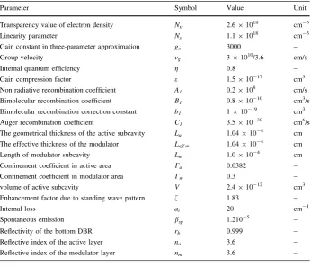
I=10Ith Fig. 4 Small-signal response of
electrooptic laser modulation calculated in themodifiedrate equation model at three different values of bias current (for 35 periods in the intermediate reflector and 17 periods in the top reflector)
0.10 1.00 10.00 100.00
-70 -60 -50 -40 -30 -20 -10 0 10 20
27
23 17 number of periods in the top reflector 13
modulation transfer function, dB
modulation frequency, GHz
[image:12.439.108.335.54.220.2] [image:12.439.220.393.265.572.2] [image:12.439.222.394.266.405.2]This can be expected since the roloff of the modulation curve at high frequencies, and hence the 3 dB cutoff frequency, are mainly determined by the lifetime of the photons in the modulator subcavity which does not depend on current in the active subcavity. With the optimised laser design (a large Riensuring the external-modulator-type operation of the
modulator section, and a more modest Rt ensuring the value of scm of the order of picoseconds), this limit is indeed of the order of hundreds of gigahertz, and thus not a concern for any realistic modulation scheme. The situation can be different however with a design of the modulator section less optimised for high speed operation. Figure5 shows that with a large (but perfectly technologically achievable) number of periods in the top reflector (henceRt), when the notch in the reflectance of the modulator section (the peak in
the transmittance) becomes narrow meaning a large photon lifetime in the modulator subcavity, the 3 dB frequency drops as low as*10 GHz. At the same time, theamplitude
of output power modulation, given the same (small) refractive index modulation, increases with an increased number of top reflector periods, though this is not shown in Fig.5 in which the transfer function is normalised to 0 dB at low frequencies. As will be discussed later, these effects of the reflector design manifest themselves also in the results oflarge
signal modulation simulations (see Fig.9).
3.3 Large signal analysis
For the large signal analysis, the rate equations, either modified or standard for comparison, are solved directly numerically for NRZ digital pseudorandom modulation. The results are used to construct an eye diagram as seen by an ideal receiver. In addition, since the modified RE model gives both the amplitude and phase/frequency of the output field, we can analyse the optical spectrum of the laser emission.
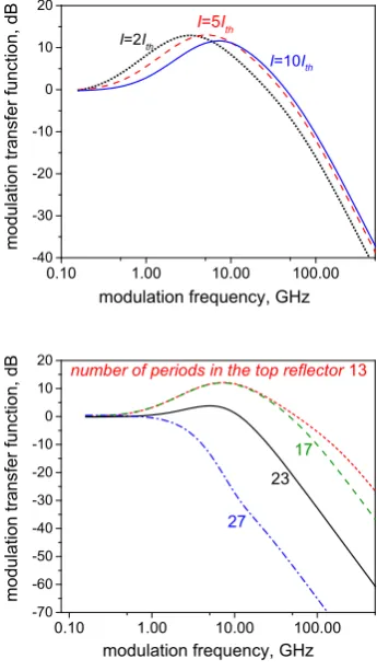
Figure6 shows a typical calculated output spectrum at 40 GBit/s, with the spectrum near the main peak, with a smoothed line for easier evaluation of the spectral width. The smoothing is performed by adjacent averaging of points, as in, say, (Ryvkin et al.2009). While the spectrum is somewhat asymmetric, implying that there is a bit of chirp in the output, the width at half maximum is 20 GHz, and ate-2close to 40 GHz, or the bit rate, or the Nyquist limit for NRZ modulation, which implies that the chirp is low.
Figure7 shows the eye diagrams calculated using the standard and modified rate equation models, respectively, for the same amplitude of refractive index modulation. As
40 60 80 100 120 140 160 180 200 0
20 40 60 80
Spectral density of output intensity, a.u.
Frequency correction ν−ν ref (GHz)
[image:13.439.200.393.453.609.2]can be expected, the modified RE model is free from unphysical abrupt changes from OFF to ON states; instead, it shows gradual transients with elements of oscillatory behaviour in the off state (which is associated with the frequency detuning between the light frequency and the resonator).
To quantify the quality of modulation represented by eye diagrams, we calculated the modulation quality factor:
Q¼Pð Þ1 Pð Þ0
rð Þ1 þrð Þ0 ð 22Þ
wherePð Þ1,Pð Þ0 are the mean values of the power corresponding to the logical one and zero states, respectively; rð Þ1, rð Þ0 are the corresponding standard deviations. In all the fig-ures below, the quality factor Q was calculated using the modified rate equation model.
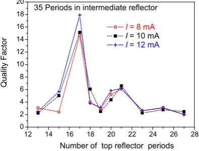
Figure8shows Q as function of the number of layer pairs (periods) in thetopreflector DBR stack. As seen in the figure, there is an optimum number, in this case around 17. When we increase the number of periods beyond that number, the photon lifetime in the modulator subcavity is increased, leading to longer transients and closing the eye diagram, hence bad quality factor. This is illustrated in Fig.9. When the number of top reflector period becomes too low, on the other hand, the modulation of power (P1-P0) becomes lower, hence lower quality factor. We observe that the optimum number of periods is not a
-30.00 -20.00 -10.00 0.00 10.00 20.00 30.00 0.00
0.50 1.00 1.50 2.00 2.50 3.00
optical power (arbitrary units)
time (arbitrary units)
-30.00 -20.00 -10.00 0.00 10.00 20.00 30.00 0.00
0.50 1.00 1.50 2.00 2.50 3.00
optical power (arbitrary units)
time (arbitrary units)
Fig. 7 Amplitude spectrum of output field at 40 GBit/s
12 14 16 18 20 22 24 26 28
0 2 4 6 8 10 12 14 16 18 20
I = 8 mA
I = 10 mA
I = 12 mA
Quality Factor
35 Periods in intermediate reflector
[image:14.439.53.389.54.189.2] [image:14.439.195.393.463.612.2]strong function of the current, so once optimised, a laser should be able to provide good modulation quality at all currents.
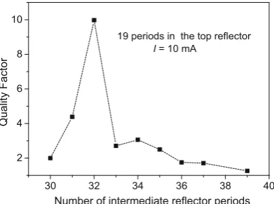
Figure10shows the modulation quality as a function of the number of periods in the
intermediatereflector. Again, there is an optimum number of periods, in this case around 32. When the number of periods is increased beyond that value, there is less output power hence somewhat lower quality factor. When the number of periods is decreased below the optimum level, the width of the transmission notch increases, leading to less efficient modulation; as a result, the eye diagram deteriorates, hence the lower quality factor. This is illustrated by Fig.11 which shows eye diagrams for I=10 mA, 19 periods in the top reflector, 33 and 31 periods in the intermediate reflector, respectively.
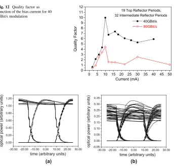
We study next the dependence of the modulation quality on current. Figure12 shows the modulation quality factor as a function of current for bit rates of 40 and 80 GBit/s. At very low current values, the modulation quality decreases simply due to lower power, given a similar distribution of the on-state. There is an optimum (rather modest) current value, though at higher currents, the modulation quality is not far below optimum. Similar qualitative tendencies are observed for 40 and 80 GBit/s; quantitatively, the quality factor is smaller than at the lower modulation rate, but still acceptable for digital communica-tions, particularly with the optimised current and design. Figures13 and14 show eye
-30.00 -20.00 -10.00 0.00 10.00 20.00 30.00 0.00
0.20 0.40 0.60 0.80
optical power (arbitrary units)
time (arbitrary units)
-30.00 -20.00 -10.00 0.00 10.00 20.00 30.00 0.00
1.00 2.00 3.00 4.00 5.00 6.00
optical power (arbitrary units)
time (arbitrary units)
(a) (b)
Fig. 9 Eye diagrams for I=10 mA, 40 GBit/s, 35 periods in the intermediate reflector, 17 (a) and 23 (b) periods in the top reflector
30 32 34 36 38 40
2 4 6 8 10
I = 10 mA
Quality Factor
Number of intermediate reflector periods
[image:15.439.52.391.56.202.2]19 periods in the top reflector Fig. 10 Modulation quality
[image:15.439.196.392.464.609.2]-30.00 -20.00 -10.00 0.00 10.00 20.00 30.00 0.00
0.50 1.00 1.50 2.00 2.50 3.00
optical power (arbitrary units)
time (arbitrary units)
-30.00 -20.00 -10.00 0.00 10.00 20.00 30.00 -0.50
0.00 0.50 1.00 1.50 2.00 2.50 3.00 3.50
optical power (arbitrary units)
time (arbitrary units)
[image:16.439.53.391.55.204.2](a) (b)
Fig. 11 Eye diagrams for I=10 mA, 40 GBit/s, 19 periods in the top reflector, 33 (a)and 31 (b)periods in the top reflector
0 5 10 15 20 25 30 35 40 45 50
0 1 2 3 4 5 6 7 8 9 10 11 12
40GBit/s
80GBit/s
19 Top Reflector Periods, 32 Intermediate Reflector Periods
Quality Factor
[image:16.439.52.397.247.580.2]Current (mA)
Fig. 12 Quality factor as function of the bias current for 40 GBit/s modulation
-30.00 -20.00 -10.00 0.00 10.00 20.00 30.00 0.00
0.20 0.40 0.60 0.80 1.00 1.20
optical power (arbitrary units)
time (arbitrary units)
-30.00 -20.00 -10.00 0.00 10.00 20.00 30.00 -0.05
0.00 0.05 0.10 0.15 0.20 0.25 0.30 0.35
optical power (arbitrary units)
time (arbitrary units)
(a) (b)
diagrams for a given structure and bit rates, for currents of 10 and 2 mA, illustrating the origin of the lower modulation quality at low currents seen in Fig.12, which appears to be due to the spread of the ‘‘one’’ level being more important when compared to the overall small difference between the ‘‘zero’’ and ‘‘one’’.
4 Discussion and conclusions
To conclude, we considered, for the first time to our knowledge, both amplitude and frequency (phase) dynamics of laser emission in an electrooptically modulated compound cavity VCSEL. As the standard rate equation model has limitations in describing high-frequency modulation, we introduced the modified rate equation model taking into account the spectrally selective nature of the laser cavity and the finite photon lifetime in the modulator. We found that the ultimate modulation frequency limit is determined by the photon lifetime of the modulator subcavity. Large signal simulations have shown that the quality of modulation depends non-monotonically on the numbers of dielectric grating periods in the top and intermediate mirrors, so that there is an optimum cavity design usable in a broad range of currents. High quality factors at modulation bit rates of up to 80 Gbit/s were predicted.
Note that in this paper, we concentrated on the electromagnetic/carrier kinetic model only, not considering the electrical circuit limitations. Indeed, Zujewski and co-authors have proved that the modulation speed limitation due to associated electrical circuit, as studied in (Zujewski et al.2011), of coupled-cavity vertical-cavity surface-emitting laser (CC-VCSEL) can be avoided using a traveling wave electrode design (Zujewski et al. 2012). They were also able to make up for the low 50Ximpedance of the modulator which allow the electrical cutoff frequency to go up to 330 GHz (Zujewski et al.2012).
Comparison with other advanced modulation schemes in VCSELs is reserved for future work.
Open Access This article is distributed under the terms of the Creative Commons Attribution 4.0 Inter-national License (http://creativecommons.org/licenses/by/4.0/), which permits unrestricted use, distribution, and reproduction in any medium, provided you give appropriate credit to the original author(s) and the source, provide a link to the Creative Commons license, and indicate if changes were made.
-30.00 -20.00 -10.00 0.00 10.00 20.00 30.00 -0.20
0.00 0.20 0.40 0.60 0.80 1.00 1.20 1.40 1.60
optical power (arbitrary units)
time (arbitrary units)
-30.00 -20.00 -10.00 0.00 10.00 20.00 30.00 -0.05
0.00 0.05 0.10 0.15 0.20 0.25 0.30 0.35
optical power (arbitrary units)
time (arbitrary units)
[image:17.439.52.390.59.204.2](a) (b)
Appendix: small signal modulation formulas
1. In thestandardrate equation model, we consider small harmonic modulation of the the reflectanceRmof the modulator subcavity at the modulation frequency X¼2p F:
Rm¼Rm0þdRmexpðjXtÞ þc:c:,
which results in small-signal modulation of the carrier density (Eq.16) and also the photon density and output power:Np¼Np0þdNpexpðjXtÞ þc:c:,P¼P0þdPexpðjXtÞ þc:c:
In the small signal approximation,dNp¼ oP oRmdRm,
The small signal analysis gives for the derivative
oP
oRm¼ hmphVoptNp0
vg
2La X2
þj crel s 1
ph out
XþX2
rel sph out1 sd1þsst1
X2þjcrelXþX2rel
ðA1Þ
wheremphis the reference frequency,Vopt¼V=Cis the optical mode volume, andXreland crel, as usual in small-signal analysis, are the relaxation oscillation frequency and decay decrement:
X2
rel
1
sstsph; ðA2Þ
sst¼ Npo og oN
1
being the stimulated carrier lifetime, and
crel¼s 1
d þs
1
st þ bspN
Npssp CNp0 og
oNp ðA3Þ
wheresd¼ o oN
N sspð ÞN þ
N snrð ÞN
h i 1
is the dynamical carrier lifetime.
Equation (A1) is different from the analysis shown by Avrutin et al. (1993) in that it takes into account modulation of both the photon density and the outcoupling loss which is related to it; it thus shows the modulation, not of the photon density inside the laser, but of the output power.
2. In thefull modifiedrate equation model, the dynamical variables include in addition to carrier and photon density also field phases and frequency as explained in the main text. The internal photon density and carrier density are then given by expressions:
dNp¼
AC jðX HÞNp0dnEO
X2þðH DÞjX ðDHþEFÞ ðA4Þ
dN ¼ NpACdnEOFjxm NpACdnEOHF
jX3 ð Dþ2HÞjX2þ½H Hð DÞ ðDHþEFÞjX H DHð þEFÞ ðA5Þ
whereA¼ vg
Leff;m La
2
þ2vgLa
orm
ox
B¼Leff;m
La
CþaH
vg
2La orm ox;C¼
Cm
L2
a
Leff;m orm onmþ
vg
2
oargð Þrm onm
orm ox
D¼ NpABeg
1þeNp0
2;E¼
NpABa0 1þeNp0þ
b scm
;
F¼ vgNpeg
1þeNp0
2 vgg;H¼
vgNp0a0 1þeNp0þ
1
scm
These variations can be recalculated into the variation of the output powerdPusing the small-signal expressions (19–21) in the main text.
References
Albugami, N., A, E.: Electrooptically modulated coupled-cavity VCSELs: the anomalous small-signal response and the large-signal modulation properties. Paper presented at the Proc, Semiconductor and Integrated Optoelectronics (SIOE) (2015)
Avrutin, E.A., Gorfinkel, V.B., Luryi, S., Shore, K.A.: Control of surface-emitting laser diodes by modu-lating the distributed Bragg mirror reflectivity: small-signal analysis. Appl. Phys. Lett. 63(18), 2460–2462 (1993)
Avrutin, E.A., Marsh, J.H., Arnold, J.M., Krauss, T.F., Pottinger, H., De La Rue, R.M.: Analysis of harmonic (sub)THz passive mode-locking in monolithic compound cavity Fabry-Perot and ring laser diodes. IEE Proc. Optoelectron.146(1), 55–61 (1999)
Blokhin, S.A., Lott, J.A., Mutig, A., Fiol, G., Ledentsov, N.N., Maximov, M.V., Bimberg, D.: Oxide-confined 850 nm VCSELs operating at bit rates up to 40 Gbit/s. Electron. Lett.45(10), 501–502 (2009) Bobrov, M.A., Blokhin, S.A., Maleev, N.A., Kuzmenkov, A.G., Blokhin, A.A., Yu, M.Z., Ustinov, V.M.: Ultimate modulation bandwidth of 850 nm oxide-confined vertical-cavity surface-emitting lasers. J. Phys: Conf. Ser.643(1), 012044 (2015)
Chen, C., Johnson, K.L., Hibbs-Brenner, M., Choquette, K.D.: Push-Pull Modulation of a Composite-Resonator Vertical-Cavity Laser. Quantum Electronics, IEEE Journal of46(4), 438–446 (2010) Coldren, L.A.: Diode lasers and photonic integrated circuits. Wiley, New York, Chichester (1995) Germann, T.D., Nadtochiy, A.M., Schulze, J.H., Mutig, A., Strittmatter, A., Bimberg, D.: Electro-optical
resonance modulation of vertical-cavity surface-emitting lasers. Opt. Express20(5), 5099–5107 (2012) Karachinsky, L.Y., Blokhin, S.A., Novikov, I.I., Maleev, N.A., Kuzmenkov, A.G., Bobrov, M.A., Bimberg, D.: Reliability performance of 25 Gbit s-1 850 nm vertical-cavity surface-emitting lasers. Semicond. Sci. Technol.28(6), 065010 (2013)
Miller, D.A.B., Chemla, D.S., Damen, T.C., Gossard, A.C., Wiegmann, W., Wood, T.H., Burrus, C.A.: Electric field dependence of optical absorption near the band gap of quantum-well structures. Physical Review B32(2), 1043–1060 (1985)
Panajotov, K., Zujewski, M., Thienpont, H.: Coupled-cavity surface-emitting lasers: spectral and polar-ization threshold characteristics and electrooptic switching. Opt. Express18(26), 27525–27533 (2010) Paraskevopoulos, A., Hensel, H.-J., Molzow, W.-D., Klein, H., Grote, N., Ledentsov, N., Kuyt, G. (2006, 2006/03/05). Ultra-high-bandwidth (>35 GHz) electrooptically-modulated VCSEL. Paper pre-sented at the optical fiber communication conference and exposition and the national fiber optic engineers conference, Anaheim, California
Rahman, L., Winful, H.G.: Nonlinear dynamics of semiconductor laser arrays: a mean field model. IEEE J. Quantum Electron.30(6), 1405–1416 (1994)
Ryvkin, B., Avrutin, E.A., Kostamovaara, J.T.: Asymmetric-Waveguide Laser Diode for High-Power Optical Pulse Generation by Gain Switching. J. Lightwave Technol.27(12), 2125–2131 (2009) Shchukin, V.A., Ledentsov, N.N., Lott, J.A., Quast, H., Hopfer, F., Karachinsky, L.Y., Bimberg, D.: Ultra
high-speed electro-optically modulated VCSELs: modeling and experimental results. Proc. SPIE 6889(1), 68890H (2008)
Stanley, R.P., Houdre´, R., Oesterle, U., Ilegems, M., Weisbuch, C.: Coupled semiconductor microcavities. Appl. Phys. Lett.65(16), 2093–2095 (1994)
Wenzel, H., Bandelow, U., Wunsche, H.J., Rehberg, J.: Mechanisms of fast self pulsations in two-section DFB lasers. IEEE J. Quantum Electron.32(1), 69–78 (1996)
Westbergh, P., Gustavsson, J.S., Kogel, B., Haglund, A., Larsson, A., Joel, A.: Speed enhancement of VCSELs by photon lifetime reduction. Electron. Lett.46(13), 938–940 (2010)
Westbergh, P., Gustavsson, J.S., Ko¨gel, B.K., Larsson, A.: Impact of photon lifetime on high-speed VCSEL performance. IEEE J. Sel. Top. Quantum Electron.17(6), 1603–1613 (2011)
Zujewski, M., Thienpont, H., Panajotov, K.: Electrical design of high-speed electro-optically modulated coupled-cavity VCSELs. J. Lightwave Technol.29(19), 2992–2998 (2011)