UNIVERSITI TEKNIKAL MALAYSIA MELAKA
DEVELOPMENT OF SMART FLAMMABLE GAS
DETECTOR
This report is submitted in accordance with requirement of Universiti Teknikal Malaysia Melaka (UTeM) for the Bachelor’s Degree of Electronic Engineering
Technology (Computer System) with Honours by
FIRDAUS BIN MARZUKI B071310643
940418015809
FACULTY OF ENGINEERING TECHNOLOGY 2016
UNIVERSITI TEKNIKAL MALAYSIA MELAKA
BORANG PENGESAHAN STATUS LAPORAN PROJEK SARJANA MUDA
TAJUK: Development of Smart Flammable Gas Detector
SESI PENGAJIAN: 2016/17 Semester 1
Saya FIRDAUS BIN MARZUKI
mengaku membenarkan Laporan PSM ini disimpan di Perpustakaan Universiti Teknikal Malaysia Melaka (UTeM) dengan syarat-syarat kegunaan seperti berikut:
1. Laporan PSM adalah hak milik Universiti Teknikal Malaysia Melaka dan penulis. 2. Perpustakaan Universiti Teknikal Malaysia Melaka dibenarkan membuat salinan
untuk tujuan pengajian sahaja dengan izin penulis.
3. Perpustakaan dibenarkan membuat salinan laporan PSM ini sebagai bahan pertukaran antara institusi pengajian tinggi.
4. **Sila tandakan ( )
Disahkan oleh:
** Jika Laporan PSM ini SULIT atau TERHAD, sila lampirkan surat daripada pihak berkuasa/organisasi berkenaan dengan menyatakan sekali sebab dan tempoh laporan PSM ini perlu dikelaskan sebagai SULIT atau TERHAD.
(Mengandungi maklumat yang berdarjah keselamatan atau kepentingan Malaysia sebagaimana yang termaktub dalam AKTA RAHSIA RASMI 1972)
(Mengandungi maklumat TERHAD yang telah ditentukan oleh organisasi/badan di mana penyelidikan dijalankan) SULIT TERHAD TIDAK TERHAD ________________________ Alamat Tetap: No. 6,
Kampung Air Merah,
86800 Mersing, Johor
Tarikh: ________________________
__________________________
Cop Rasmi:
DECLARATION
I hereby, declare that this thesis entitled “Development of smart Flammable Gas Detector” is the result of my own research except as cited in references.
Signature : ………
Name : ………
APPROVAL
This report is submitted to the Faculty of Engineering Technology of UTeM as a partial fulfillment of the requirements for the degree of Bachelor’s Degree of Electronic Engineering Technology (Computer System) with Honours. The member of the supervisory is as follow:
v
ABSTRACT
vi
ABSTRAK
vii
DEDICATIONS
To my beloved parents,
Marzuki bin M.Nor and Hamidah Binti Abdullah for raising me become who I
viii
ACKNOWLEDGEMENT
First and foremost, I would like to express my deepest gratitude to Mdm. Nurliyana binti Abd. Mutalib for giving me an opportunity working under her supervision throughout this project Encik Ahmad Sayuthi bin Mohamad Shokri for taking up her place when she’s not available during her leaves. The project would not be completed under the time frame without their supervision.
Not forgetting the staffs of Faculty of Engineering Technology; my academic advisor, Mdm. Siti Haryanti Binti Hj Hairol Anuar for her professional advices in this project, and also the other staffs who had been helping me indirectly.
ix
TABLE OF CONTENTS
UNIVERSITI TEKNIKAL MALAYSIA MELAKA ... i
DECLARATION ... iii
ABSTRAK ... vi
DEDICATIONS ... vii
ACKNOWLEDGEMENT ... viii
LIST OF TABLES... xi
LIST OF FIGURES ... xii
LIST OF ABBREVATIONS, SYMBOLS AND NOMENCLATURES... xv
CHAPTER 1 ... 1
1.0 Introduction ... 1
1.1Background ... 1
1.2Problem Statement ... 2
1.3Objectives ... 2
1.4Project Scope and Limitations ... 2
1.5Contribution Of Research ... 3
1.7Summary ... 3
CHAPTER 2 ... 4
2.0 Introduction ... 4
2.2Arduino Uno ... 8
2.3 Gas Sensor ... 10
2.4 Past Related Research ... 16
CHAPTER 3 ... 22
3.0 Introduction ... 22
x
3.2Flowchart of Project ... 23
CHAPTER 4 ... 28
4.0 Introduction ... 28
4.1 Hardware Analysis ... 28
4.2 Program Analysis (Coding) ... 36
4.3 Project Analysis ... 41
4.4 Discussion ... 43
CHAPTER 5 ... 45
CONCLUSION AND FUTURE WORK ... 45
5.0 Introduction ... 45
5.1 Conclusion ... 45
5.2Recommendations ... 46
5.3Future Work ... 46
REFERENCES ... 47
xi
LIST OF TABLES
Table 2.1: GSM Evolution Timeline ...20
Table 2.2: Characteristic of MQ-2 gas sensor... 30
Table 2.3: Component used in Gas Detector... 32
Table 4.1.1: Specification of Arduino Uno Board... 44
Table 4.1.2: Characteristic of I2C LCD Display... 45
Table 4.1.3: DC Fan Characteristic... 46
Table 4.1.4: Specification of LED...47
Table 4.1.5: Characteristic of Buzzer SFM-27 DC3~24V...48
Table 4.1.6: Specifications of GSM SIM900A...49
Table 4.1.7: Specifications of MQ-2 Gas Sensor...50
xii
LIST OF FIGURES
Figure 1.1: Block Diagram of Flammable Gas Detector...2
Figure 2.1: Official Logo of GSM...4
Figure 2.1.2: Illustration of SMS operation...7
Figure 2.2.1: Arduino Uno Board...9
Figure 2.2.2: Square wave for LED to dim...10
Figure 2.3: MQ-2 Gas Sensor...11
Figure 2.3.1.1: MC119 Catalytic Flammable Gas Sensor...12
Figure 2.3.1.2: Electrochemical Gas Sensor ME3-C2H4...12
Figure 2.3.1.3: MH711A NDIR CO2 Sensor...13
Figure 2.3.1.4: MQ-5 Semiconductor Sensor...14
Figure 2.3.2: MQ-2 Test Circuit...14
Figure 2.4.1.2:Schematic Diagram of Gas Detector Using GH-312 Sensor...16
Figure 2.4.1.4: Output When The Device Sensing No Gas...18
xiii
Figure 2.4.2.1: Output When The Device Sense No Gas...19
Figure 2.4.2.2: MQ-3 Gas Sensor...20
Figure 2.4.2.3: Schematic Diagram...20
Figure 3.1: The Flow chart of Completing project...23
Figure 3.2: Flow chart of the Development of Smart Flammable Gas Detector...24
Figure 3.3: Block Diagram of Development of Smart Flammable Gas Detector...25
Figure 4.1: Hardware setup...28
Figure 4.1.1: Arduino Uno...29
Figure 4.1.2: I2C LCD Display...30
Figure 4.1.3: DC Fan...31
Figure 4.1.4: Light Emitting Diode (LED)...32
Figure 4.1.5: Buzzer SFM-27 DC3~24V...33
Figure 4.1.6: GSM SIM900A...34
Figure 4.1.7: MQ-2 Gas Sensor...35
Figure 4.2.1: Calibration of MQ-2 gas sensor...36
Figure 4.2.2: MQ-2 Resistance calculation...37
xiv
Figure 4.2.4: Coding to send SMS...39
Figure 4.2.5: Coding for other Component...40
Figure 4.3.1: Project design...41
Figure 4.3.2: Design Inside the project...41
Figure 4.3.3: Calibration of MQ-2 gas sensor...42
Figure 4.3.4: Project Operation...42
xv
LIST OF ABBREVATIONS, SYMBOLS AND
NOMENCLATURES
LED - Light Emitting Diode
GSM - Global System for Mobile communication
CEPT - European Conference of Postal and Telecommunications TDMA - Time Division Multiple Access
ETSI - European Telecommunication Standard Institute GPRS - General Packet Radio Service
MSC - Mobile Switching Centre
SMSC - Short Messaging Service Centre
PWM - Pulse-width modulation
GND - Ground
IDE - Integrated Development Environment
LEL - Lower Explosive Limit
PPM - Parts per million
LCD - Liquid crystal display
DC - Direct current
1
CHAPTER 1
INTRODUCTION
1.0 Introduction
This chapter introduces the project with its background, problem statement, objectives, scope and project significance, to provide a sense of purpose and reasons to proceed with this project.
1.1Background
2 1.2Problem Statement
The problem faced in detecting the type of flammable gas (Greg, A. 1997), is the current device that used in the market now can detect gases but mostly the specified gases only. So this device can detect multiple type of flammable gases. Most of the device in the market used battery. Once the battery runs out, it need to be changed. But not with this device, the battery is rechargeable. Moreover, this device used GSM module which allow the user to be alerted by the notification from the device compared to others.
1.3Objectives
The main objectives of this project are based on aspect as listed below: i. To detect flammable gases in certain area.
ii. To develop a program based on arduino mobile. iii. To design a prototype of flammable gas detector.
1.4Project Scope and Limitations
[image:17.595.124.513.661.704.2]Once the sensor detect the flammable gases, the sensor will calculate the gas volume and send it to the LEDs. The green LED shows that the amount of the gas is low, yellow LED shows the amount of the gas is in the middle range and red LEDs shows the volume of the gas in the place is in higher volume that are very dangerous almost 100% LEL (Bruce, H. 2004). The device then send the notification through the GSM modul and the user would be alerted. The levels of the gases is reduced when the gases is reduced.
3 1.5Contribution Of Research
By doing this project, it has contributed to a new knowledge about type of flammable gas and detector that widely used in industries. Detector accuration is depends on the type of gas it sense in order to avoid injury in some places. Gas like butane and propane are some of the example that can lead to a fire. Moreover, sensor also play a main role as it has various type and different accuration range. It must be choosen carefully or injury will occured due to robustness of the sensor. Through this project, analysis is known as part of the important thing in daily life. Without analysis of project, this project can be the same as other devices out there with no speciality.
1.7Summary
4
CHAPTER 2
LITERATURE REVIEW
2.0 Introduction
This chapter provides understandings of theories and previous researches that are related to this final year project. This includes an overview of GSM, the specifications of sensors, similar products from all kind of sources, and more.
2.1Global System for Mobile Communications
Global system for mobile communication also known as GSM uses digital radio transmission services in order to provide voice, data, and multimedia communication services and it is a wide area wireless communications system. Cellular technology is a telecommunication applications that growing rapidly nowadays. This is because GSM system coordinates the communication between a mobile telephones which is mobile stations, base stations, and interconnecting switching systems. Each GSM radio channel is divided into frames that hold 8 time slots. It has 200 kHz wide channels for each (Lawrence Harte, 2008).
[image:19.595.238.402.598.692.2]5 Figure 2.1 illustrate the official logo of GSM. GSM has been the most successful communication system and widely used in the world today. It has over four billion subscriber to communicate with anyone from every country because GSM was founded to provide specifications that define the function and interface of different technologies (Saily, et al., 2011). GSM is used to minimize the limitation in technological design but in a meantime it maintain the wide range of application (TelecomSpace, 2010).
2.1.1History of GSM
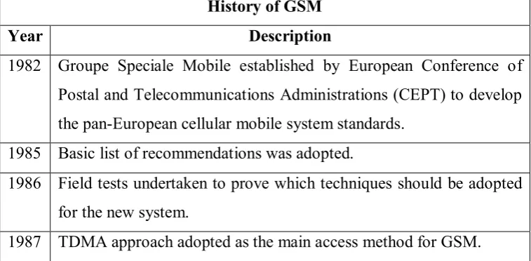
[image:20.595.149.528.560.746.2]Cellular telecommunication is a fastest growing telecommunication application(Stuckmann, P., 2003). In order to get where it is now, GSM took many years in the result of both technical development and international cooperation. In the year 1982, European Conference of Postal and Telecommunications Administration (CEPT) established Groupe Speciale Mobile in order to develop the pan-European cellular mobile system standard. Then basic list of recommendations was adopted in 1985. This first step has made GSM known to the world with technologies that help people. Through my project, the use of GSM is needed to create Flammable Gas Detector which is different in the market today. Through table 2.1, we can see the timeline of GSM revolution since year of 1982.
Table 2.1: GSM Evolution Timeline History of GSM
Year Description
1982 Groupe Speciale Mobile established by European Conference of Postal and Telecommunications Administrations (CEPT) to develop the pan-European cellular mobile system standards.
1985 Basic list of recommendations was adopted.
1986 Field tests undertaken to prove which techniques should be adopted for the new system.
6 Europe produced the first GSM Technical Specification.
Initial Memorandum of Understanding was signed by telecommunication operators from 12 member countries.
1988 GSM system validation undertaken
1989 ETSI takes on responsibility for managing the GSM standards. 1990 GSM specifications released (phase 1).
1991 Commercial launch of the GSM service.
The first SMS was sent, GSM standard was expanded to 1800 MHz frequency band.
1993 Coverage of main roads GSM services start outside Europe. Telecom Australia became the first network operator. 1995 GSM specifications released (phase 2).
New technologies services were launched commercially (fax, data, and SMS messaging)
1996 Prepaid GSM SIM cards were launched. Subscribers exceeded 10 million.
2000 GPRS services were launched commercially. GSM subscribers exceeded 500 million in this year. 2002 Multimedia Messaging Service (MMS) were introduced. 2004 Announcement made at 3GSM in Cannes.
2005 75% of the worldwide cellular network uses GSM network. GSM subscriptions exceeded 1.5 billion.
7 2.1.2 Short Message Services by GSM
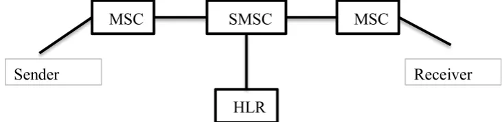
[image:22.595.152.518.350.439.2]GSM provides a lot of technologies such as voice transmission and fax transmission, but with this project, Short Message Services (SMS) will be focussed on because Flammable Gas Detector need it as a further step in evolution of gas detector. Basically, the sender of an SMS sends the SMS via a signalling channel to a Mobile Switching Centre (MSC). Once, the MSC receives an SMS from the sender, it transparently forwards the SMS to the Short Messaging Service Centre (SMSC). If the message from the mobile device contains the address of the subscriber’s SMSC, the SMS can be forwarded from the foreign MSC to the home SMSC without the need for an international SMSC database (Sauter, 2011). The illustration of this system can be seen as Figure 2.1.2 below.
Figure 2.1.2: Illustration of SMS operation
Home Location Register (HLR) is a database from a mobile network. This is the place which information of mobile subscriber is stored. The transmission of this short messages use a connectionless and protected packet switching protocol (Eberspacher, et al., 2001).SMS has the capability to receive or send short messages at the mobile station, known as TS21 and TS22. TS21 is a point-to-point version of SMS. It allows a single station to send a message up to 160 characters. But for TS22, it is the optional implementation of the capability to send the short messages from a mobile station.
MSC SMSC MSC
HLR
8 2.2Arduino Uno
Arduino is an open-source prototyping platform (Banzi, 2011). This system is based on hardware and software that is easy to use. By using this Arduino boards, it has the ability to read inputs such as a finger on a button, light on a sensor, or even read messages from social network and turn it into an output like activating a motor, turning on LEDs and can also publishing something online. This can be done by sending a set of instructions to the microcontroller on the board. But, in order to do the things, Arduino programming language based on Wiring, and the Arduino Software (IDE) based on Processing must be used.
Arduino was born at the Ivrea Interaction Design Institute and it is an easier tool for fast prototyping and has been used to create thousands of projects. Arduino is known in a wider community by providing new needs and challenges. It differentiates its offer from simple 8-bit boards to products for Information and Communications Technology (ICT) applications, wearable, 3D printing, and embedded environments from everyday objects to a more complex instruments. All Arduino boards are completely open-source that give users to do or build projects independently by giving their particular needs.
2.2.1Arduino Board
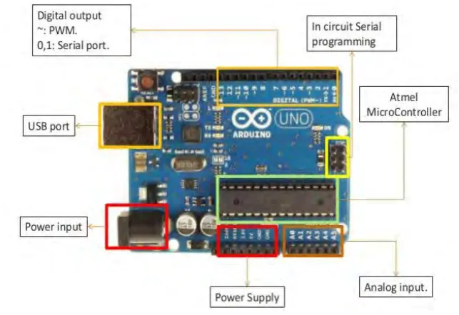
9 Figure 2.2.1: Arduino Uno Board
Based on figure 2.2.1, there are 14 digital Input/Output pins that has number from 0 to 13. These are the most important pins on Arduino because it can be used as either input or output. Through this board, it is a very helpful in the form of the core of many projects. For Digital output, it can make the signal of these pins to write or read as on or off.