University of Southern Queensland
Faculty of Engineering and Surveying
Development of a Drivetrain System
for a Formula SAE-A Race car
A dissertation submitted by
Mr Matthew Harber
In fulfilment of the requirements of
ENG4111 and 4112 Research Project
towards the degree of
Bachelor of Engineering (Mechanical)
Abstract
This project encapsulates one of many areas that make up the USQ Motorsport vehicle for entry into its second Formula SAE-A competition. The aim of this project was to undertake the design and development of the drivetrain system, including brakes and wheels, which would optimise performance and reliability in the competition.
To begin the project many different drivetrain systems and components were
researched to gain the knowledge and understanding required to select an appropriate system. Investigation into the drivetrain in the 2004 vehicle was also conducted along with the review of the competition rules and regulations. The development of the vehicle is a team project and therefore required good communication and cooperation among team members to design a successfully competitive racecar.
University of Southern Queensland
Faculty of Engineering and Surveying
ENG4111 & ENG4112
Research Project
Limitations of Use
The Council of the University of Southern Queensland, its Faculty of Engineering and Surveying, and the staff of the University of Southern Queensland, do not accept any responsibility for the truth, accuracy or completeness of material contained within or associated with this dissertation.
Persons using all or any part of this material do so at their own risk, and not at the risk of the Council of the University of Southern Queensland, its Faculty of
Engineering and Surveying or the staff of the University of Southern Queensland.
This dissertation reports an educational exercise and has no purpose or validity beyond this exercise. The sole purpose of the course pair entitled "Research Project" is to contribute to the overall education within the student’s chosen degree
programme. This document, the associated hardware, software, drawings, and other material set out in the associated appendices should not be used for any other purpose: if they are so used, it is entirely at the risk of the user.
Prof G Baker Dean
Certification
I certify that the ideas, designs and experimental work, results, analyses and conclusions set out in this dissertation are entirely my own effort, except where otherwise indicated and acknowledged.
I further certify that the work is original and has not been previously submitted for assessment in any other course or institution, except where specifically stated.
Matthew Harber
Student Number: Q12222212
Acknowledgements
I would like to acknowledge and thank my supervisor Chris Snook and also Derek Mulder for all their guidance and assistance throughout the course of my project.
As a member of the USQ Motorsport team I would like to thank all my fellow team members involved in this years challenge:- Ray Malpress, Selvan Pather, Melinda Plank, Tony O’Neill, Cristina Poppa, Rueben Molloy, Scott Coombes, Bruce Llewellyn, Kevin Gilham, Scott Corsan, Dos, and anyone else who has helped the team to compete in this years Formula SAE-A competition.
I would like to thank the USQ workshop staff Chris Galligan and Brian Aston for their patience and assistance in manufacturing the car.
Finally I appreciate any support given by the team sponsors who helped make this project possible.
Matthew Harber
Contents
ABSTRACT ... I
ACKNOWLEDGEMENTS... IV
CHAPTER 1 ...1
INTRODUCTION...1
1.1 Introduction ...1
1.2 Project Aim...2
1.3 Project Objectives ...2
1.4 Overview of Dissertation...3
1.5 Conclusion...3
CHAPTER 2 ...4
BACKGROUND...4
2.1 SAE Competition ...4
2.2 Drivetrain ...6
2.2.1 SAE Constraints ...6
2.2.2 Transmission ...6
2.2.3 Power Transfer Systems...8
2.2.3.1 Chain Drive ...8
2.2.3.2 Belt Drive ...9
2.2.4 Reduction box...9
2.2.5 Differentials...10
2.2.6 Drive shaft joints ...13
2.2.6.1 Universal joint ...14
2.3 Wheels and Tyres...16
2.3.1 SAE Constraints ...16
2.3.2 Wheel and Tyre Selection ...17
2.4 Braking System ...20
2.4.1 SAE Constraints ...20
2.4.2 Types of Braking Systems...20
2.4.3 Brake Component Descriptions...22
CHAPTER 3 ...23
DRIVETRAIN SELECTION AND DEVELOPMENT...23
3.1 Introduction ...23
3.2 Design criteria...23
3.3 Design Selection ...25
3.4 Drivetrain Development ...28
3.5 Final Gearing ...30
3.6 Axle loading...31
3.6.1 Engine Performance ...32
3.6.2 Tyre Friction...32
3.6.3 Vehicle Performance ...33
3.7 Conclusion...36
CHAPTER 4 ...38
CENTRE SHAFT DESIGN AND ANALYSIS...38
4.1 Introduction ...38
4.2 Centre Shaft Design...38
4.2.1 Positioning...38
4.2.2 Flanges...39
4.2.3 Splines ...40
4.2.4 Material selection ...41
4.2.5 Manufacture...42
4.3 Centre Shaft Analysis ...43
4.3.2 Stress analysis...46
4.4 Fatigue life ...52
4.5 Conclusions ...60
CHAPTER 5 ...61
DIFFERENTIAL DESIGNS...61
5.1 Introduction ...61
5.2 Differentials...61
5.3 Torsen Design...63
5.3.1 University Special Torsen ...63
5.3.2 Torsen II ...64
5.3.3 Performance characteristics...65
5.3.4 Development into drivetrain...66
5.3.5 Cost Analysis...68
5.4 Modified Limited Slip Differential ...69
5.4.1 Performance characteristics...70
5.4.2 How to develop into drivetrain...72
5.5 Conclusion...73
CHAPTER 6 ...74
ASSOCIATED DRIVETRAIN COMPONENTS...74
6.1 Introduction ...74
6.2 CV joint assembly...74
6.2.1 CV shaft modification ...76
6.3 Rear hub flanges...77
6.4 Gear Reduction Box ...79
6.5 Chain and Sprocket Drive ...81
6.6 Bearings...83
6.6.1 Mounting of bearings ...84
6.6.2 Bearing loads...84
6.6.3 Bearing life ...85
CHAPTER 7 ...87
WHEELS, TYRES AND THE BRAKING SYSTEM...87
7.1 Introduction ...87
7.2 Wheels Selection...87
7.3 Tyre Selection ...88
7.4 Brake System Design ...89
7.4.1 Front and Rear Selection ...89
7.4.2 Conceptual Brake Design...90
7.4.3 Braking Force Analysis ...91
7.5 Conclusion...95
CHAPTER 8 ...96
CONCLUSIONS AND FURTHER WORK...96
8.1 Introduction ...96
8.2 Project Summary ...96
8.3 Further Work...97
8.4 Conclusion...98
REFERENCES ...100
APPENDIX A ...102
PROJECT SPECIFICATION...102
APPENDIX B...105
RELEVANT FORMULA SAE-A REGULATIONS...105
B.1 Drivetrain ...106
B.2 Wheels and Tyres...107
B.3 The Braking System ...108
B.4 Cost Report...109
APPENDIX C ...115
COST REPORT...115
C.1 Cost Report...116
APPENDIX D ...119
PERFORMANCE TABLES...119
D.1 Cornering Traction Force ...120
D.1.1 Centripetal Acceleration...120
D1.2 Resultant Normal Force...120
D.2 Gear Tables ...123
APPENDIX E...124
DETAILED DRAWINGS & SOLID MODEL...124
E.1 Torsen Differential Drawings ...125
E.2 Centre Shaft Drawing...127
E.3 CV Shaft Modification ...128
Chapter 1
Introduction
1.1 Introduction
Last year a team of engineering students from University of Southern Queensland (USQ) entered a competition organised by the Society of Automotive Engineers (SAE) for the first time. This year a new team of students are continuing the challenge and hoping to improve on the efforts of their fellow. This competition allows a team of young engineers to design and manufacture a formula-style racing car and to compete against other universities in a number of events. As a member of the 2005 USQ Motorsport team it is my responsibility to develop the drivetrain system, with the addition of wheels, tyres and the braking system.
To begin this project investigation into the Formula SAE-A competition rules and regulations was required. The competition has strict guidelines on the safety features of the cars and other limitations to restrict the power and cost in order to challenge the imagination and ingenuity of competitors. Following this a great deal of research was done into the many different systems available to be incorporated into the drivetrain of this style of racecar. This research will not only lead to my design decisions for this years car, but should also become a foundation for future students involved in developing a race car for USQ Motorsport in future competitions.
The task of designing and manufacturing a competitive vehicle requires a team of students each responsible for specific areas of the car. As a result of this the project requires great teamwork and communication to be completed successfully,
sponsorship efforts in order to gain enough finances to allow the purchase of all necessary components.
1.2 Project Aim
My project aim is to undertake the design and development of a drivetrain system for a Formula SAE racing car that will optimise performance and reliability whilst minimising cost and weight. Wheels, tyres and the braking system have also been included with the drivetrain. The design must meet all Formula SAE-A rules and regulations including all safety features.
1.3 Project Objectives
The objectives of this project are to review the Formula SAE-A competition rules and scope of the Formula SAE-A competition. Then research literature relating to differentials and related drivetrain systems to gain solid knowledge and
understanding of the concepts. This includes comparing and evaluating the information concerning differential performances and specifications. Select an appropriate system for use in the 2005 USQ FSAE-A challenge. Design an appropriate drive system to carry the power of the engine to the differential
1.4 Overview of Dissertation
This dissertation is structured as follows:
Chapter 2 Provides some foundation knowledge to understand drivetrain systems, braking systems and wheels and tyres.
Chapter 3 Describes the selection and development process of the drivetrain for the Formula SAE car.
Chapter 4 Details the centre shaft design and analysis.
Chapter5 Covers the differential designs considered and recommendations for future implementation.
Chapter 6 The selection and analysis of the associated drivetrain components.
Chapter 7 Details the selection of the wheels, tyres and braking system along with the analysis of a braking system for possible future use.
Chapter 8 Concludes the dissertation and suggests further work.
Appendices All of the relevant SAE regulations, detailed drawings and solid model of drivetrain components, gearing tables, cost report and project specification.
1.5 Conclusion
As a member of the USQ Motorsport team entry in the 2005 Formula SAE-A competition, I am responsible for the design and development of all drivetrain components, the braking system, wheels and tyres. The aim is to develop an
Chapter 2
Background
2
.1 SAE Competition
To develop a drivetrain system for a formula SAE racecar one must first understand what formula SAE racing is and what the formula SAE-A competition is all about. To begin with the formula SAE competition was created so students could
experience an interesting and exciting engineering project before completing their studies and entering the world as a qualified engineer. The cars are built with a team effort over a period of about one year and are taken to a host institution for judging and comparison with other competitors. The Society of Automotive Engineers developed this idea in the USA and has more recently spread to Australia, Japan and Europe.
For the purpose of the competition, the scenario given to the teams was that a manufacturing firm has engaged them to produce a prototype car intended for the non-professional weekend autocross racer. Therefore it is very important the car has high performance in terms of its acceleration, braking, and handling qualities. The car must be low in cost, easy to maintain, and reliable. In addition, the car's marketability is enhanced by other factors such as aesthetics, comfort and use of common parts. The challenge to the design team is to design and fabricate a prototype car that best meets these goals and intents. Each design will be compared and judged with other competing designs to determine the best overall car.
performance trials and high performance track endurance. The maximum available score in each event is listed below.
Static Events Points
Presentation 75 Engineering Design 150 Cost Analysis 100
Dynamic Events
Acceleration 75 Skid-Pad Event 50 Autocross Event 150 Fuel Economy Event 50 Endurance Track Event 350
Total Points 1000
The first of the static events is the cost and manufacturing analysis, which is an assessment of the cost considerations used to produce the car. Evaluation of a team's ability to present their prototype car to a manufacturing company will be evaluated in the presentation event. Finally the design event evaluates the engineering skills, innovation and effort to meet the requirements of the competition as well as rationale behind their design.
separately on a tight course. This is called the autocross event and will combine acceleration, braking and cornering into one event. The final test will be the endurance and fuel economy event where the vehicles reliability and fuel economy are tested to evaluate the overall performance of the car.
2.2 Drivetrain
To develop a drivetrain system for a Formula SAE racecar one must also understand what components make up this system. The drivetrain includes a gearbox, a power transmission or transfer system i.e. chain and sprocket or drive shaft, a differential, axles, CV joints, wheels and tyres and finally the braking system. Each of these components will be briefly described for later evaluation in the selection and design of the drivetrain. The Formula SAE rules outline specific safety restrictions that must be incorporated into the design of the drivetrain.
2.2.1 SAE Constraints
The following Formula SAE rules are those relevant or directly related to the drivetrain system. The drivetrain must have:
• Four wheels not in a straight line
• Any transmission and drivetrain can be implemented
• All exposed high speed components must be guarded by scatter shields • Only tyres touching the ground
2.2.2 Transmission
speeds. The three configurations of transmissions available are manual, automatic and variable.
A manual transmission allows the operator to manually select the desired gear ratio by moving a shift lever. This directly connects the engine to the differential through a set of gears. For the selected gear to engage through dogteeth the spinning shaft and collar must be rotating at the same speed as the gear. This is achieved through the use of synchronisers. Synchronisers, also known as a synchromesh unit, act as a brake or clutch by making contact before the teeth to synchronise their speed through a frictional surface. This enables the teeth to be meshed easily and without noise or damage. Without synchronisers the operator would have to vary the engine revs between gear changes to allow the teeth to engage. This is known as double clutching. An important feature required for a manual transmission is a clutch.
A clutch is used in a manual transmission to engage and disengage the engines output shaft to the transmission. The purpose for this is that an engine must be started and running at speed before a load can be applied. A clutch also allows for low or reverse gear to be selected when the vehicle is stationary and the load to be applied to the engine gradually. The clutch gradually transfers the engines torque to the drivetrain by increasing the friction between surfaces until they spin at the same speed.
the centrifugal motion of the fluid. Whilst it does not require any manual operation, the fluid coupling is not as efficient as the manual clutch because the automatic transmission can never reach the engine speed.
Continuously Variable Transmissions (CVT’s) are a transmission with an infinite number of gear ratios. The CVT does not actually use any gears but rather achieves this by changing the radius of the drive and driven pulleys. Variable-diameter pulleys must always come in pairs to ensure the belt remains tight. The pulleys are
effectively two cones facing each other with the ability to move in and away from each other. A V-belt rides in the groove between the two cones and as the cones move in or out, the belt rides higher or lower in the groove effectively varying the diameter and as a result the drive ratio. The advantages to this design are that the engine will remain in the optimum power range regardless of speed and acceleration, thereby optimizing efficiency and acceleration. There is also no need for a clutch because the belt is loose at idle. Only recently are CVT’s beginning to be accepted for use in motor vehicles. This is because of the advancement in durability and the amount of torque they can handle, combined with the reduction in cost.
2.2.3 Power Transfer Systems
A power transfer system must be capable of transferring the engines torque from the output of the transmission to the input of a differential. In the majority of motor vehicles this is done with a rotating drive shaft, connected to the transmission and differential by universal joints. However there are a number of different methods that can be used to effectively transfer this power. Other methods include a chain and sprocket, belt drive and gear meshing.
2.2.3.1 Chain Drive
common use pushbikes, motorcycles and engine timing. The main advantage of a chain drive is not being limited by the distance between the drive and driven shafts. However some limitations include only being capable of transmitting power in one plane and alignment is critical for its proper operation. Also this system requires regular maintenance and inspection for chain and sprocket wear. The difference in the diameter and number of teeth on the sprockets are what determines the gearing ratio. A chain tensioner or idler sprocket is used to accommodate and adjust for small changes in chain tension due to a change of sprocket size or elongation of the chain due to wear.
2.2.3.2 Belt Drive
A belt drive system connects the two shafts through a tensioned belt wrapped around two pulleys. This has similar limitations to the chain drive where the pulleys must be aligned in the same plane and requires an adjustable belt tensioner. This is important because the belt tension creates the required friction between the belt and the pulleys; consequently slippage can be another disadvantage to this system. There are wide ranges of different belts available including a toothed belt that is similar to the chain drive and has eliminated the problem of slippage.
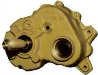
2.2.4 Reduction box
Figure 2.1: Gear reduction box
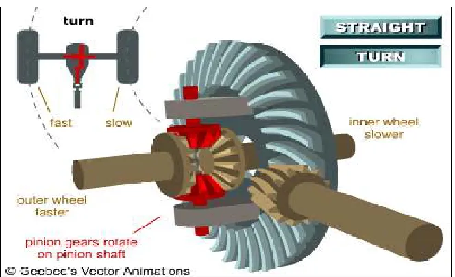
2.2.5 Differentials
The function of a differential is to transfer torque to both rear drive axles whilst also allowing them to spin at different speeds. The name came from its ability to allow both wheels to rotate at different speeds or to differentiate. The need for this differential action is because as a car turns a corner, the outside wheel must travel along a larger radius than the inside wheel over the same period of time. Velocity is given by distance / time therefore around every corner the outside wheel must travel faster than the inside wheel. This affect on wheel differentiation increases as the radius of turn decreases.
If the rear wheels were unable to differentiate as in the case of a solid rear axle or locked differential, than the outside wheel would force the inside wheel to rotate faster. This additional force to the inside wheel can have two negative affects. Either the tyre will break traction and slip or the tyre will hold traction and act against the turning motion of the car creating understeer. There are two kinds of differential available, an open and limited-slip designs, which will be described in more detail.
the torque equally between the axles regardless of rotational speed. The major disadvantage with this diff is that because it offers no resistance to differentiation, the drive force is limited to the tyre with the least amount of traction. This limitation led to the designs of limited slip differentials.
Figure 2.2: Open Differential
A limited slip differential (LSD) is designed to transfer more torque to the wheel with the most traction. There are a variety of LSD’s available that will allow normal differential operation when cornering but when slippage occurs more torque is transferred to the non-slip wheel. A few different types of LSD are the clutch-type, the torsen, a viscous coupling and a locking differential.
torque if the other wheel has no traction whatsoever. Furthermore by altering the friction can set the amount of force required to overpower the clutch.
Figure 2.3: Clutch-Type Limited Slip
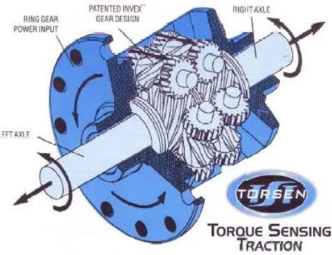
[image:22.612.246.402.148.296.2]A Torsen meaning ‘Torque Sensing’ LSD is a less common type usually found in small four-wheel drive cars. As seen in the figure below the drive axles are joined by a helical gearing arrangement. This gear design creates a torque bias ratio between the drive axles that allows the wheel with the most traction to be supplied with the majority of torque. For example a torque bias ratio of 4:1 means that the torsen can deliver to the tyre with the most traction, 4 times the torque that can be supported by the lower traction tyre. Therefore the torsen can provide much more traction force under such conditions than the open differential.
[image:22.612.214.453.514.698.2]A viscous coupling is again not very common but can be found in some all-wheel vehicles to transfer torque between the front and rear set of wheels. This LSD contains two sets of plates inside a sealed housing that is filled with a thick or viscous fluid. One set of plates is connected to each output shaft, and under normal conditions both the plates and fluid will all rotate together at the same speed. However when there is a difference in velocity between shafts i.e. when one set of wheels is losing traction, than the set of plates corresponding to those wheels will also rotate faster. This causes the viscous fluid between the plates to speed up which then in turn force the other set of plates to rotate faster. This effectively transfers torque from the slipping wheels to the non-slip wheels. The disadvantage with this differential is that it cannot transfer torque until the wheels are slipping to produce a large enough difference in rotation between shafts.
A locking differential, also known as a spool, acts as though the drive shafts are connected together and does not allow any wheel differentiation. However, this locking action can be manually activated so that the operator can choose when this is to be engaged. Disengaged the differential will simply act as an open differential. Activating mechanisms can include electric, hydraulic or pneumatic systems to lock the side gears together.
2.2.6 Drive shaft joints
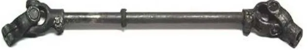
2.2.6.1 Universal joint
The most common universal to be used in a vehicle is the cross-and-yoke joint, or Hooke’s join t. It consists of two yokes and a cross, with needle roller bearings carried in cups between the surfaces of the yoke and cross. A yoke is attached to both the driving and driven shafts, and connected by the cross that allows the shafts to operate at different angles. When a change in angle occurs between the shafts, the joint will impart rotation at a varying velocity, due to geometry of the joint. The rotation of the driven shaft momentarily accelerates and decelerates as the universal joint rotates. The greater the angle of drive, the greater this effect will occur. However a solution to this problem is to incorporate two universal joints into the drive system, connected by an intermediate shaft. The second joint will cause
[image:24.612.165.482.372.424.2]fluctuations in the rotational speed opposing that of the first joint, thus cancelling this effect out.
Figure 2.5: Universal Joints
2.2.6.2 Constant Velocity (CV) joint
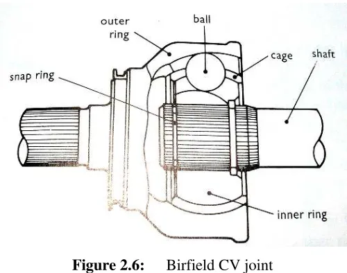
There are three kinds of CV joint available. The first is the Birfield joint, typically used as the outer joint on the drive shaft, next is the Double-offset joint and the Tripod joint, both typically used as the inner joint.
Figure 2.6: Birfield CV joint
A double-offset joint is very similar to the Birfield joint, except that the housing or outer ring is longer. This gives longer grooves for the balls and allows more axial movement to compensate for changes in shaft length. This is important because the larger the angle in the shaft, the greater the distance becomes between the joints.
Figure 2.7: Double-offset CV joint
[image:25.612.182.474.404.604.2]Figure 2.8: Tripod CV joint
2.3 Wheels and Tyres
Tyre selection is arguably the most important decision concerning the performance of a vehicle. The contact patches of the tyres are the single interface connecting the racing car to the surface of the track. Therefore all acceleration, braking and cornering forces performed by the car must be transferred through the tyres. Providing your engine has sufficient power then the traction between the tyres and the racetrack will become the limiting factor on potential performance.
2.3.1 SAE Constraints
The following Formula SAE rules are those relevant or directly related to the wheels and tyres. They include:
• Wheels must be 203.2mm (8.0 inches) or more in diameter • Single retaining wheels nuts must have a device to retain nut • Tyres are only to be cut or treaded by the manufacturer • Dry tyres may be slicks or treaded
2.3.2 Wheel and Tyre Selection
Before selecting a tyre one must understand how a tyre behaves and the effect of different variables such as the diameter, width, aspect ratio, stiffness, compound, tread and also tyre pressures.
Tyres perform better when a larger area of rubber is in contact with the road. One way to increase this area is to use a tyre with less void area. The void area is all the area not in contact with the ground, such as the tread cut into all road tyres. This is why most forms of motorsport use a slick tyre. Using a smooth flat tyre with no tread means no void area and optimises the contact area with the road, enhancing traction in dry conditions. However these grooves are required for traction in the wet. The grooves allow for water to disperse out from underneath the tyre maintaining the contact of rubber with the road. Without the treaded grooves the tyre would ‘aquaplane’ over water lying on the road, meaning a film of water would rem ain between the tyre and the road surface, diminishing contact with the road surface and losing traction and control over the vehicle. Therefore for safety and performance in wet conditions a treaded tyre with some void area for dispersing water is required.
Tyre Pressures are also extremely important when considering tyre performance. Lower tyre pressures will increase the contact area with the road but decreases the tyre’s sidewall strength. Sidewall strength is extremely important for cornering to avoid the tyre deforming. When a sidewall deforms, the tread shifts out from under the wheel and the tyre begins to roll onto its side, not just losing grip but also the reaction time of steering inputs. At lower tyre pressures there is less reinforcement to stretch and support the sidewall. Therefore it is more important to maintain sidewall strength than it is to decrease the tyre pressures for a little extra contact area.
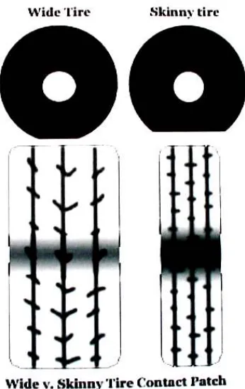
It is often argued that wider tyres are better because they increase the area of rubber contacting the track surface. Whilst wider tyres are better, it is not because of the increased width and area of the contact patch, but rather the change in shape of the contact patch.
Figure 2.9: Contact patch shapes
is also advantageous to the vehicles performance because it is the front and back edges of the contact patch that allows the tyres tread to deform and create slip angle.
Rotational inertia is another important consideration in high performance wheels and tyres. The greater the rotational inertia from the wheels and tyres than a greater amount of torque is required to slow or accelerate, making the car less responsive or sluggish. The further the mass of the wheels and tyres are from the axle, than the greater the rotational inertia. By using a larger diameter wheel, not only is the mass further from the axle, but also the wheel and tyre require more material for the larger surface area thereby increasing weight. Therefore by increasing or decreasing the diameter of the wheel, the rotational inertia is changing exponentially. To minimise a racing cars rotational inertia and optimise the vehicles acceleration and braking responsiveness, use lighter and smaller diameter wheels and low profile tyres. Reducing the width of the wheels will also decrease the rotational inertia however not as drastically and has adverse affects to the cornering performance as seen above.
Understeer is the term used for when the vehicles front wheels do not follow the turning circle and continues in a straight path tangent to the curve of the corner. This is also known as ‘push’ in racing because the car pushes the front wheels straight ahead and doesn’t allow them to maintain traction and turn. Conversely oversteer is a term used when the vehicles rear end does not follow the curved path of the corner and slides out, usually spinning the car. This is also known as ‘loose’ in racing terms because when the rear end loses traction it slides out away from the corner and does not tightly follow the corner.
2.4 Braking System
Braking or decelerating a car is just as important to overall performance as acceleration. Not to mention the safety aspects of using appropriate and reliable brakes, but also a car with a better braking system can be just as fast around a racetrack as a car with more torque and acceleration. It is very important that the design of the braking system be more than adequate for its given situation.
2.4.1 SAE Constraints
The following Formula SAE rules are those relevant or directly related to the braking system. The braking system must:
• Act on all 4 wheels and be operated by a single control
• Have 2 independent hydraulic circuits, each with its own fluid reserve • Brake-by-wire systems are prohibited
• Be protected by scatter shields
• Have brake pedal over-travel switch to stop ignition and fuel pump if brake fails
2.4.2 Types of Braking Systems
Primarily there are two main types of braking systems used in cars. These are a disc brake system and a drum brake system. Drum brakes consist of a pair of stationary shoes that are forced radially outward against the inner surface of the rotating drum that is fixed to the wheel. The friction surface is the outer surface of the shoes that contact the inside of the drum and therefore slows the rotation of the wheel.
Figure 2.10: Drum brake assembly
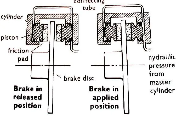
The disc brake system is a far more common arrangement and can be found in use in the majority of modern vehicles. A rotating disc connected to the wheel of the vehicle is clamped by a calliper that forces a pair of brake pads against either side of the disc. This system is also powered by means of hydraulic pressure. The brake pads have a friction surface and when clamped against the disc, slow the rotation of the wheel. The advantages of this system are that the disc allows for better heat dissipation and therefore more frictional force can be applied. Also the disc brake system is a more simplistic design, and allows the brake pads to be inspected and replaced with ease.
[image:31.612.173.478.488.692.2]2.4.3 Brake Component Descriptions
Master cylinder:- is the cylinder operated by the driver in a hydraulic brake system. It contains a piston that displaces fluid to create pressure.
Calliper:- is the component that straddles the brake disc and clamps it when pressure is applied to the system. It consists of pistons that push brake pads toward either side of the rotor, which slows the rotation.
Brake pad:- has a metal back with friction material used to force against rotating components in a brake system to slow them down.
Rotor:- the brake disc in a disc brake assembly. When brake is
operated the brake pads are clamped against this disc, which is attached to the wheel.
Chapter 3
Drivetrain Selection and Development
3.1 Introduction
The most significant part of this project was the selection and design of the
drivetrain. To begin the process of selecting the best system for our Formula SAE-A racing car I focused on the design criteria and then produced some conceptual designs to choose from for development. Engine performance and the shafts gearing and loading information are used to perform a detailed analysis on all of the
components in the drivetrain. The final decisions regarding the design and
development of each drivetrain design has been summarised to show the reasoning behind the final selection for the drivetrain.
3.2 Design criteria
The design criteria for the drivetrain system consisted of the limitations and objectives set by both the Formula SAE-A competition and the USQ Motorsport team’s goals. These included the Formula SAE rules and regulations, the
competition’s judging criter ia including cost, engineering design and performance, and the team’s aims including weight, reliability and budget.
regulations most relevant to my area have been included in Appendix B. The development of the race car is a team project and I had to liase with the other members of the team to insure the design of the drivetrain coordinated well with the rest of the car. The most significant areas of the car that the drivetrain had to adapt to were the chassis, engine and suspension. The engine determines the maximum amount of power and torque the drivetrain will have to transmit, the chassis must support all components of the car and the suspension is a critical factor in the cars performance. The rear suspension also connects and supports some drivetrain components therefore the development of both these systems required close interaction and communication.
The team’s aim for this year’s car was to improve the performance of the car
primarily by decreasing the weight of each component where possible to improve the power to weight ratio of the vehicle. By saving a little weight in each area this will add up to make a significant difference however this had to be achieved without sacrificing reliability. This was determined to be the most cost effective way to improve the performance characteristics of the car in acceleration, braking and cornering. The cost of each design is another very important criteria that must be considered when selecting an appropriate design. Not only is cost a significant area judged at the competition but also the design must be able to be developed in accordance with the team’s specific budget for the entire car.
In summary there were many important criteria to consider during the design and selection of the drivetrain system. These criteria were mainly governed by the competitions judging events and the USQ Motorsport team’s goals of developing a competitive car by reducing the weight to increase performance at minimal cost.
3.3 Design Selection
The drivetrain design can be any system capable of transmitting the power from the engine through to the tyres contacting the road. The drivetrain was to be designed for a rear-wheel drive independent suspension vehicle. Thus the design options included a combination of a chain and sprocket or belt and pulley drive, a differential or solid axle and CV joints or universal joints. All of these components are described in the drivetrain background.
The first design option was the chain and sprocket drive with a solid rear axle. An example of this system can be found on racing karts. The benefits to this design are: -
• No losses through slippage • Cheap
• Light weight • Reliable
• Ease of maintenance and replacement • Simple design
• Long operating life
However the disadvantages of this design are: -
• Cornering performance affected • Tyres required to slip whilst cornering • Chain requires tensioning
The second design option was a toothed-belt drive with a solid rear axle. Examples of this system are generally not found in the drivetrain of vehicles but rather used on the engine to drive the camshaft from the crankshaft. The benefits to this design are: -
• Long operating life • Quiet operating • Simple design • Lightweight
• Ease of maintenance and replacement
However the disadvantages of this design are: -
• Tensioning required
• Width of belt required to transfer torque • Tyres required to slip whilst cornering • High cost of both belt and toothed pulleys
The third design option involves a gear reduction box to drive a solid rear axle. This design could have also been incorporated into a system with a chain drive and a differential. The benefits of this design include: -
• Reduces size of rear sprocket • Allows optimum final drive ratio
• Allows the rear axle to moved closer to the engine, shortening wheelbase and increasing the weight distribution to the rear wheels
• Additional weight
• Difficulty designing housing for oil bath • Maintenance required
• Cost of gearing
The fourth design option was a chain drive system to a Torsen differential. This limited slip differential is a popular option used in the Formula SAE competitions and a University Special Torsen differential is available to Formula SAE teams for a special discount price. Other Torsen designs are available out of a Rav4 and an Audi Quattro. The benefits to this design are: -
• Small, lightweight differential
• Increased performance characteristics • No forced tyre slippage
• Reliability
• Long operating life
However the disadvantages to this design include: -
• Difficulty of designing housing for oil bath • Cost
• Maintenance required • Chain tensioning required
• Performance characteristics • Design points
• No forced tyre slippage
However the disadvantages to this design are: -
• Complex to design and manufacture • Heavy
• Unknown cost and reliability • Chain tensioning required • Requires actuating control
After considering the advantages and disadvantages of each system according to the design criteria, a chain drive to a solid rear axle was chosen. This was primarily based on simplicity, reliability and low cost. Although the Torsen differential appears to be the optimum option to implement into the car for increased performance, it was decided to leave this design for incorporation into cars in future years when time and financial resources are available. Whilst a solid rear axle system compromises cornering performance, the team’s aim was to further develop the 2004 car for improvement and this is possible through redesign and weight reduction of the 2004 solid rear axle drivetrain system.
3.4 Drivetrain Development
joint was readily available the more appealing option would have been to source and analyse a universal joint of appropriate size. However a much smaller CV assembly was sourced from a 1983 model Suzuki SS80V. This assembly only required shortening of the CV shaft to accommodate the drivetrain design. The hub flanges from the Suzuki were also utilised, as no modification was required to fit both the CV assembly and wheel stud pattern.
Once these components were sourced the centre axle design was finalised and manufactured. Details on the design and manufacture of the shaft are summarised in the following chapter. The preferred final drive ratio was then calculated and the necessary sprockets purchased. The positioning of the rear wheels is determined by the suspension, therefore having the distance of the rear axle behind the engine limited by this, additional analysis was required to confirm the sprocket sizes would allow for the required amount of chain wrap around the drive sprocket. This found that the rear sprocket intended for use only just allowed for sufficient chain wrap, so a slightly smaller rear sprocket was ordered as a precaution.
The rear axle then needed to be mounted to the chassis by its support bearings. Not only did housings have to be manufactured to hold the bearings, but also the bracket the bearing housings would be mounted to had to allow for horizontal displacement to tension the chain. It was decided to allow the entire rear axle to slide horizontally to tension the chain and remove the need for a chain tensioner. Whilst a chain tensioner would increase the amount of chain wrap on the drive sprocket, it also increases the frictional losses of the drivetrain and adds unnecessary componentry and weight to the car. Another disadvantage of a chain tensioner discovered from the 2004 car was the significant increase in operating noise during engine braking.
When the rear axle was fixed in position inside the chassis, the rear disc brake calliper had to be mounted to the chassis also allowing for the horizontal
last to make certain the length will be accurate. Once all of the components have been sourced and manufactured, the drivetrain will be assembled and tested.
3.5 Final Gearing
The final gearing of the drivetrain is required to calculate the loading of the shafts and the performance characteristics of the vehicle. Torque, acceleration and top speed are all major performance parameters affected by the final gear ratio. A higher gear ratio lowers a vehicles top speed but increases its torque and acceleration. Therefore the ideal gear ratio would be the highest ratio possible to allow the vehicle to reach the required top speed, thus maximising the torque and acceleration. The 2004 car featured a 15 tooth front sprocket driving a 60 tooth rear sprocket resulting in a final drive ratio of 4. This reveals a top speed capability of 151 km/hr. From researching previous entrants of the Formula SAE-A competition and a technical specification given from the Society of Automotive Engineers, the maximum speed obtainable in the competition is around 120 km/hr. However due to the tight course the average speeds are kept to around 40 – 50 km/hr increasing the benefits of better acceleration and lowering the importance of top speed.
Another factor was that last year the car primarily stayed in second gear for the majority of the course, signifying the car may have been geared a little low and wasn’t maximising the cars potential performance. For these reasons it was decided to increase the final drive ratio of the drivetrain for this year. The 60-tooth driven sprocket at the rear cannot be increased in size due to availability of space; therefore the 15 tooth front sprocket is to be replaced by a smaller drive sprocket. The smallest size available from Yamaha was a 13-tooth sprocket. This would increase the final gearing from 4 to 4.615.
The top speeds in each gear at the maximum design rpm (11 000rpm) were
Primary Reduction Ratio = 82/48 (1.708)
Secondary Reduction Ratios: 1st = 37/13 (2.846) 2nd = 37/19 (1.947) 3rd = 31/20 (1.550)
4th = 28/21 (1.333)
5th = 31/26 (1.192) 6th = 30/27 (1.111)
Appendix D displays the change in speeds and torque due to this ratio change.
The selection of the final gear ratio is a result of the right compromise between acceleration, torque and top speed. The optimum drive ratio will differ between each track layout and can be fine tuned by selecting different sized sprockets.
3.6 Axle loading
The loading of the axle must be determined to design the components of the drivetrain. After assuming the masses of each component are negligible the forces acting on the axle simplified to just the torque being transmitted by the chain through the rear sprocket. This torque also results in a force pulling the axle forward toward the engine. To determine the maximum torque applied to the rear axle a combination of three different approaches was taken. First was the study into the potential
3.6.1 Engine Performance
To begin with the maximum torque transmitted to the rear axle was estimated using engine performance. The engine being used in USQs Formula SAE racing car is a 1994 model Yamaha YZF600 motorcycle engine, which has unrestricted power and torque figures of approximately 60 kW and 61Nm respectively measured from the crankshaft. To be able to estimate the true torque available at the rear axle as
accurately as possible, there are a number of factors that need to be considered. First the Formula SAE rules require that the air intake be restricted to a narrow 20mm opening. Second the engine is not new therefore the internals of the engine have been worn and will no longer produce the same power and torque ratings. Finally the frictional losses from the transfer of torque through the gearbox and chain drive must also be considered. Assuming 15% of torque is lost through frictional forces, and at least another 5 % lost through the intake restrictor, the maximum torque will be:
Nm
T
=
(
0
.
15
+
0
.
05
)
×
61
=
48
.
8
Therefore multiplying this by the primary and secondary gear ratios and again by the final drive ratio will give an estimate of the expected torque from the engine. First gear is used because it has the highest ratio and will deliver the most torque.
Nm
T
7
.
1094
615
.
4
846
.
2
708
.
1
8
.
48
max=
×
×
×
=
3.6.2 Tyre Friction
The coefficient of friction will vary according to tyre compounds from different manufacturers, tyre temperature and wear, the cleanliness and roughness of the tracks surface and many other conditions. Therefore after researching many internet sites
! "$#%&'()+*,- .$/&01#2(3*547698:(<;6>=6-?A@.$#B@$C7"D7/&
average value for the coefficient of friction was taken as 1.
mg
F
=
where: F = Force (N) m = Mass (kg)
g = acceleration due to gravity (m/s²)
The normal force on the rear tyres is:
N
mg
F
N9
.
81
2403
.
5
100
70
350
×
=
=
=
The frictional force with a coefficient of friction of 1:
N
F
F
R=
Nµ
=
2403
.
5
×
1
.
0
=
2403
.
5
r
F
T
=
Rwhere: T = Torque (Nm) FR = Frictional force (N)
r = Radius (m)
Nm
T
5
.
664
2765
.
0
5
.
2403
=
×
=
3.6.3 Vehicle Performance
3.6.3.1 Acceleration
The straight-line acceleration of the car is unknown since it has not yet been built, however a prediction of the acceleration can be estimated from the results of FSAE teams from previous years. The majority of teams claim to be capable of accelerating from 0 to 100 km/hr in between 3 to 5 seconds.
Therefore using a desired performance of 0-100 in 4 seconds gives an acceleration of 6.94 m/s². This is clearly on the higher end of the scale and is most likely an overestimate, however this is preferable to an underestimate when calculating the maximum torque to provide a safety factor into the stress calculations. To be capable of this acceleration the torque produced in the rear axle would be 672Nm. This value is very close to the estimated torque value limited by the traction of the tyres.
3.6.3.2 Cornering
Torque can only be transferred through an axle if the tyre has enough traction force to support this load. During cornering the weight distribution of the car changes and the normal force acting on the inside wheel is reduced, usually resulting in loss of traction. In order to investigate when more torque is transferred to the outside wheel, the forces acting on each wheel during cornering were calculated. Analysing the different situations where wheel slip is likely to occur will also give a better
Figure 3.1: Free-body diagram of moments
Assuming a mass of 350 kg including driver, and a weight distribution of 45:55 front to rear the mass at the rear tyres is:
kg
m
R)
192
.
5
100
55
(
350
×
=
=
Therefore the normal force acting on the inner wheel around a corner is found to be:
0
2
3
4
=
−
×
−
×
+
×
=
∑
M
mg
w
ma
h
CN
w
where: M = Moment (Nm)
N4 = Normal force on inside rear tyre (N)
N3 = Normal force on outside rear tyre (N)
2w = Rear wheel track (m)
The normal force acting on the outer wheel can also be found.
a
a
w
w
mg
h
ma
N
w
N
w
mg
h
ma
M
C C5
.
38
2
.
944
2
.
1
6
.
0
81
.
9
5
.
192
24
.
0
5
.
192
2
0
2
4 4 3−
=
×
×
+
×
×
−
=
×
+
×
−
=
=
×
−
×
+
×
−
=
∑
The centripetal acceleration around various radii corners taken at a range of speeds has been has been calculated and used to tabulate the normal force on each tyre in each situation. Wheel slip will occur when the torque becomes greater than the
EFHG-IJE(K!L1MON+L1F$IP:Q RTSUVWXYW.Z$W[X$\]^(XV_)`aW.bWW)cd_J^e^f_-g/VW-hAickj'lmlW)chiDnAop_)chdX3VqBrsW_-g/V
situation when the inside will lose traction.
tAuYvwxzy{k|A}av~~/$/w1ya[u|~ A~|y%|m~~vv!/wmy7|~~(Hv!)yv!|wO|a~|By$|a}zya$u/w}
racing slicks, the traction force was calculated and compared with the estimated torque at the tyres.
Given the range of corners we are likely to encounter during the competition from given information found in the competition specifications, and a range of speeds the corners may be attempted at, the results clearly show the circumstances at which tyre slippage will occur with a solid rear axle and therefore the benefit of a differential. This data will also be useful to determine the possibility of the extreme situation where all of the torque is transferred through one tyre, doubling the loads on that axle.
3.7 Conclusion
behind the final design selection of the solid rear axle. The maximum torque produced has been estimated a number of different ways in an attempt to find the most accurate assumption. The torque estimate from the engine power can only be based on if the wheels of the car never break traction, which is clearly not the case given the vehicle characteristics. For this reason calculations estimating the tractive force of the tyres were undertaken to include this limiting factor and find a more realistic torque value.
Chapter 4
Centre Shaft Design and Analysis
4.1 Introduction
This chapter covers the design and the analysis of the centre rear axle. The design and analysis on the solid rear axle used in the 2004 car was researched and used as a base for improving the design. Detailed stress analysis, fatigue life and deflection calculations were all performed to accurately analyse the shaft. The manufacturing process is also outlined as a record of how the design was created.
4.2 Centre Shaft Design
4.2.1 Positioning
The design of the rear axle is dependant on many factors. These include engine positioning, the physical space available inside the chassis, location for supports to hold the axle in place and the CV assembly. The position of the engine determines the position of the rear sprocket flange that must align with the front sprocket, and also the distance between the front and rear sprocket centres that influences the angle of wrap of the chain. There must be enough physical space to mount the rear axle, sprocket and disc brake assembly inside the chassis frame. The horizontal
required to hold the axle in place. The support bearings will be fixed to the chassis frame and must also be as close to the sprocket flange and brake disc flange as possible to offer maximum support and reduce shaft deflection and bending stresses. The final consideration was to the CV assembly that each end of the centre shaft must drive. This influences the vertical positioning of the axle and the size of the splines either end of the shaft.
4.2.2 Flanges
Two flanges are required along the rear axle, one to support the driven rear sprocket and carry the input torque, and the other to fix the single rear brake disc to. These flanges must be strong enough to withstand the stress and fatigue of repetitive loading. The flanges feature a shoulder to locate the centre of the rotor and sprocket respectively, and were designed to match the standard bolt pattern of the brake rotor from the Yamaha motorcycle. During the manufacture of the shaft the flanges were required to be made as separate components, which were to be welded to the shaft. To ensure any distortion or other effects caused by the welding procedure were corrected, the shaft and flanges were machined and ‘trued’.
There was a concern with the alignment of the rear sprocket with respect to the front sprocket. After the misalignment problems encountered last year I intended to finalise the position of the rear sprocket flange after the engine had been located in the chassis, hence eliminating any chance of alignment error. However due to the time constraints of this project the centre shaft had to be manufactured before the engine testing was complete, and the engine could be fitted into the car. In an attempt to overcome any misalignment of the rear sprocket, vigorous measuring and
4.2.3 Splines
The inner CV joint from the Suzuki CV assembly sourced has an internal spline. This was important because an external spline is much easier and cheaper to manufacture. To measure the spline dimensions accurately the CV joint was disassembled and cleaned thoroughly, so it could then be examined under a profile projector. The projector used was a Mitutoyo PJ300 and it magnified a projection of the spline for measurements to be taken. The spline is a 22 tooth involute spline that has an outside diameter of approximately 24mm. The measurements read from the profile projector were the tooth land, tooth depth and pressure angles.
Sources of error and inaccuracies arose from the wear induced in the spline so a number of teeth were measured and then the average dimension recorded. Below is a sketch of the spline profile and the results of the spline dimensions. The spline also required a clip groove to be machined toward the end of the spline to locate the C-clip that would hold the CV joint onto the shaft and prevent it from sliding out.
Table 4.1: Spline Dimensions
22 Tooth Involute Spline Dimensions
Outer Diameter 24mm
Root Diameter 22mm
Tooth Land 1.4mm
Tooth Depth 1.0mm
Pressure Angle 21°
4.2.4 Material selection
The most significant innovation compared with last years rear axle was the use of hollow bar steel from which the centre axle was manufactured. This was chosen to meet the goal of weight conservation for the development of the 2005 car. The only consequence of this is that since the CV splines are quite small, only 24mm in diameter, so small lengths of solid bar will be welded to either end of the shaft from which the splines will be cut. The most appropriate sizes of hollow bar readily available range from 16-25mm I.D. and 32-40mm O.D. However outside diameters are not of particular importance, as the shaft will be machined during manufacture.
The internal diameter of the hollow bar was to be no smaller than the diameter of the spline, so that the solid end could fit into the hollow bar and support the weld. Using an internal diameter smaller than this would cause a serious stress concentration in the material, creating a likely point of failure. Therefore a 22mm I.D. x 36mm O.D. hollow bar was chosen to allow for the maximum diameter of the spline and the necessary wall thickness required to maintain adequate strength and shoulder the bearings.
higher strength alloy steel is that it would allow for smaller diameters and a thinner wall thickness to be used, therefore decreasing the weight even further.
The grade of solid steel bar required for the splines on either end of the axle was determined after a stress analysis of the splines was performed. These analyses illustrated later in this chapter determined the strength of material required to avoid deformation and failure. It was revealed that the AISI 1020 mild steel used for the rest of the centre axle would not be strong enough so alloy steel AISI 4140 should be used.
4.2.5 Manufacture
When designing a component and analysing what material it should be made from the manufacturing process must be considered. It is essential to understand that a design can appear flawless however if it cannot be made than the design is of no use. For this reason any good design must take into account the manufacturing procedure likely to be undertaken when making the component, and allow for ease of
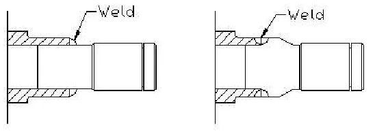
[image:52.612.192.466.563.660.2]manufacture. During the design process after I had sketched my initial design I approached the staff from the USQ Engineering Workshop, who would be the professionals to make the centre axle, and discussed the procedure that would be undertaken to manufacture the shaft and what I needed to incorporate into my design to allow for this process. The most significant change made from the initial design was to allow for a stronger weld to join the solid bar material to the ends of the hollow bar.
Once the design was complete the manufacture began by cutting the mild steel hollow bar material to length. Then the solid alloy steel ends were cut to length and machined to fit into and up against the hollow bar. The two flanges were then bored to fit the hollow shaft using a lathe. The alloy steel stub ends were then preheated before welding in place to ensure the strength of the weld between the two different metals and minimise any weakness of the heat-affected area. The sprocket flange was made wider than required to allow for adjustment in the alignment of the engine and drive sprocket. Once the engine is fitted into the chassis the sprocket flange can be machined back to size where appropriate. The two flanges were welded to the shaft with the stub ends, and the entire shaft was machined down to the correct dimensions and tolerances. It was critical for this process to occur after the welding to eliminate any welding effects. The splines were to be cut with the CNC machine using a modified fly-cutter, and so a few practice runs were done to ensure the quality and fit of the spline into the CV joint. The last process was to drill the flanges to suit the rear sprocket and brake rotor.
4.3 Centre Shaft Analysis
4.3.1 Shaft loading
The most significant loads on the centre shaft are due to the disc brake and the chain drive, which transfers torque through the rear sprocket. The weight of the drivetrain components are considered negligible so will not be considered in the analysis of the shaft. The chain drive produces a tangential force on the rear sprocket resulting in a torque of 664.5Nm, as found in the previous chapter. Under normal operating conditions the solid rear axle will share torque equally between both rear tyres. However this analysis will also consider the extreme condition of all the torque being transferred through only one tyre. The maximum tangential force acting on the sprocket (Dp = 303.33mm) is found to be:-
N
F
F
r
T
F
p
37
.
4381
1517
.
0
5
.
664
=
=
=
The bending moment created in the shaft is from the chain attempting to pull the rear sprocket forward. The support bearings either end of the shaft act against this force and hold it in place. The initial chain tension is neglected as well as any centrifugal effects of the chain.
Lr Sprocket Rr
y
x
F
60mm 250mm
The sum of moments around the left bearing finds the right bearings reaction force.
(
) (
)
N
R
Rr
M
r L848
31
.
0
06
.
0
37
.
4381
0
0
=
∴
×
−
×
=
=
∑
Sum of forces in the y-direction finds the left bearing reaction force.
N
L
L
R
F
F
r r r Y37
.
3533
848
37
.
4381
0
=
−
=
∴
+
=
=
∑
The shear force, bending moment and torque diagrams are illustrated below in Figure 4.4. Shaft Shear Force Bending Moment
Torque 0 0
0 0
0 0
3533.37 N 848 N
[image:55.612.192.443.383.666.2]4381.37 N 848 N 3533 N 212 Nm 332.3 Nm 60mm 250mm
4.3.2 Stress analysis
Figure 4.5: Critical locations for analysis
The first point of concern is the possible shearing of the involute spline. According to (Machinery’s Handbook, 2000) if the length of engagement of the spline is between 0.75 to 1.25 times the pitch diameter, then the shear strength of the spline will exceed that of the shaft from which it is made. Since the internal spline matching the
external spline we are creating already exists, then the length of the spline has
already been set and was measured to be 30mm. Therefore the length of engagement of the spline is 30/24 = 1.25 times the pitch diameter and should then exceed the shear strength of the material.
Thus the next point of concern is the shearing of the shaft ends. Two conditions will be analysed to determine the shear stress due to torsion. The first is under normal loading conditions during straight-line acceleration, when torque is shared equally between both tyres. The second is an extreme case of all of the torque being
transferred through one wheel. The root diameter of the spline is 22mm therefore the shear stress due to torsion can be found by using equation 3.9 (Beer & Johnston 2002):-
J
Tr
=
τ
where: HH)e$[ ¡£¢-¤
r = radius (m)
J = Polar moment of inertia (m^4)
The torque and radius of shaft are known, and the polar moment of inertia can be found from the following equation. For a circular cross-section where d = diameter:
32
4
d
J
=
π
Therefore under normal loading conditions 332.3Nm torque will create a shear stress of: 32 4 022 . 0
011
.
0
3
.
332
××
=
πτ
= 158.94 MPa
To predict the equivalent tensile yield strength from the shear stress the Maximum Distortion Energy Criterion was used. From figure 8.16 (Juvinall & Marshek 2000):
58
.
0
max
τ
σ
Y=
where:
1
Y = Yield strength (MPa)2
max = Maximum shear stress (MPa)Therefore the equivalent tensile strength under normal loading conditions is:
Next to consider extreme loading of the centre shaft, with a possible 664.5Nm of torque creating a shear stress of:
MPa
83
.
317
32
022
.
0
011
.
0
5
.
664
4=
×
×
=
τ
π
τ
The equivalent tensile strength for extreme loading conditions is:
MPa
548
58
.
0
83
.
317
=
=
σ
σ
The next area of concern is the 30mm bearing surface made from AISI 1020 mild steel hollow bar. This section of the shaft is subject to combined loading of shear stress with torsion and bending stress with torsion. The following formulas that predict this combined stress were sourced from (Beer & Johnston 2002).
I
Mc
Ib
VQ
=
=
σ
τ
where: V = Shearing force (N) Q = First moment of area (m³) I = Moment of inertia (m4) b = width of section (m) M = Bending moment (Nm) c = radius of shaft (m)
664.5Nm of torque. To find the induced combined stress at this point the direct shear stress is found initially where:
3 6 3 3 2
10
36
.
1
)
011
.
0
015
.
0
(
3
2
)
(
3
2
3
)
(
4
)
(
2
1
3 3 2m
Q
r
r
r
r
r
r
y
A
Q
i o i o i o −×
=
−
=
−
=
−
−
=
=
π
π
4 6 4 4 010
28
.
0
)
011
.
0
015
.
0
(
4
)
(
4
4 4m
I
r
r
I
i −×
=
−
=
−
=
π
π
Therefore the direct shear stress is:
MPa
d572
.
0
03
.
0
10
28
.
0
10
36
.
1
37
.
3533
6 6=
×
×
×
×
=
− −τ
Torsional shear stress is then found.
To find the total shear stress the direct and torsional shear stresses are added together.
MPa
t d25
.
251
68
.
250
57
.
0
max max=
+
=
+
=
τ
τ
τ
τ
The equivalent maximum tensile stress due to combined shear stresses can now be found.
MPa
433
58
.
0
25
.
251
=
=
σ
Now the combined bending and torsional stresses acting on the shaft must be considered. The bending diagram in Figure 4.4 shows the maximum bending moment occurring at the location of the sprocket flange (location 3). So the bending stress due to the 212Nm moment is found.
MPa
I
Mc
b b79
.
53
018
.
0
212
) 4 011 . 0 4 018 . 0 ( 4=
×
=
=
−σ
σ
πThe torsional shear stress is found once again under the extreme loading condition of 664.5Nm of torque.
To find the total combined stresses the formulas for Mohr’s Circle for biaxial stress can be used. To begin the principal stresses must be found using equation 4.16 (Juvinall & Marshek 2000).
2 2 1
2
2
,
2
−
+
±
+
=
x yxy
y
x
σ
τ
σ