DESIGN AND DEVELOPMENT OF LIGHTWEIGHT CHASSIS FOR UTeM FORMULA STYLE’S RACE CAR
MOHD SHAARANI BIN MOHD HASHIM
This report is presented in
Partial fulfillment of the requirements for the
Degree of Bachelor of Mechanical Engineering (Automotive)
Faculty of Mechanical Engineering Universiti Teknikal Malaysia Melaka
i
‘I/We* have read this thesis and from my/our* opinion this thesis
is sufficient in aspects of scope and quality for awarding Bachelor of Mechanical Engineering (Automotive)’
Signatures : ………..
ii
DESIGN AND DEVELOPMENT OF LIGHTWEIGHT CHASSIS FOR UTeM FORMULA STYLE RACE CAR
MOHD SHAARANI BIN MOHD HASHIM
This report is presented in
Partial fulfillment of the requirements for the Bachelor of Mechanical Engineering (Automotive)
Faculty of Mechanical Engineering Universiti Teknikal Malaysia Melaka
iii
“I declare this report is on my own work except for summary and quotes that I have mentioned its sources”
Signature : ………..
iv
v
ACKNOWLEDGEMENTS
Thanks to Allah because of bless I am sincerely appreciative to my lecturer, Mr. Muhd Ridzuan bin Mansor for serving as my supervisor and for providing guidance
while conducting the research and the writing of this Projek Sarjana Muda (PSM). I thank the laboratory management especially the lab technicians for their cooperation and support. I also want to thank my father , Mr Hashim and my mother, Siti Alwiyah for their continued support and encouragement in everything I do. All these years of education have been made possible by their support and love.
Last but not least, I thank everyone who involved directly and indirectly in this project. The sacrifice and commitment given towards me earning my bachelor’s degree are indescribable and without them, this PSM thesis would have been impossible. Lastly, hope that all that have been study and research in this thesis can be use as a references to the other student in the future.
vi
ABSTRAK
vii
ABSTRACT
viii
TABLE OF CONTENT
CHAPTER TITLE PAGE
PREFACE Ii
DEDICATION Iv
ACKNOWLEDGEMENT V
ABSTRAK Vi
ABSTRACT vii
TABLE OF CONTENT viii
LIST OF TABLE X
LIST OF FIGURE Xi
NOMENCLATURE xiv
CHAPTER I INTRODUCTION 1
1.10 Objective 1
1.20 Problem statement 2
1.30 Scope 2
CHAPTER II LITERATURE REVIEW 4
2.10 Competition
2.1.0 Competition rules 4
ix
2.1.2 Car 6
2.20 Types of Chassis Design 7
2.2.1 Ladder frame 7
2.2.2 Space frame 8
2.2.3 Backbone Chassis 8
2.2.4 Monocorque 9
2.2.5 Carbon Fiber Monocoque 9
2.30 Types of chassis used in Formula
SAE
10
2.3.1 Tubular Steel Space Frame 11
2.3.2 Metal Monocoque 11
2.3.3 Composite Semi-Monocoques 12
2.40 Types of material possibly use 12
2.4.1 Steel 13
2.4.2 Plain Carbon Steel 13
2.4.3 Mild steel 14
2.4.4 Medium carbon steel 14
2.4.5 High carbon steel 15
2.4.6 Alloy Steels 15
2.4.7 Stainless Steel 15
2.4.8 Aluminum 16
2.50 Torsional Stiffness 16
2.60 Metal inert gas (MIG) welding 18
2.6.1 Welding technique 19
CHAPTER III METHODOLOGY 20
3.10 Flow chart 20
3.1.0 Flow chart of PSM I 21
3.1.1 Flow chart of PSM II 22
3.20 Analysis of last year’s chassis 23
3.30 Consultation 23
3.3.1 Last Year Team Members 23
x
3.3.3 Workshop Staff 24
3.40 Process 24
3.50 Design study and process 27
3.5.1 Aims 27
3.5.2 Size 28
3.5.3 Strength 28
3.5.4 Weight 28
3.5.5 Miscellaneous 29
3.5.6 Requirements 29
3.60 Formula SAE Study and Research 30
3.70 Modeling 30
3.80 Selection of materials 31
3.8.1 Comparisons 31
3.8.2 Conclusion in choosing the material
33
3.90 Finite element analysis 33
CHAPTER IV DESIGN ANALYSIS AND PROCESS 36
4.10 Flow chart of the design process 37
4.20 Design planning 38
4.30 3D Model of previous chassis 39
4.40 Concept generation 40
4.4.1 First concept 41
4.4.2 Second concept generation 41 4.4.3 Third concept generation 42
4.50 Explanation of evaluation concept 43
4.5.1 Characteristics 41
4.5.2 Concept selection 44
4.5.3 Weighted Rating Method 45 4.5.4 Final concept selection 45 4.5.5 3D model of new design 45
4.60 Design dimension and specification
analysis
xi
4.6.1 Main roll hoop 53
4.6.2 Front hoop 54
4.6.3 Bulkhead 56
4.6.4 Rear box 57
4.6.5 Side impact member 57
4.5.6 Engine bay 58
CHAPTER V FINITE ELEMENT ANALYSIS 60
5.10 Define load 61
5.20 Torsion Displacement Analysis 63
5.2.1 Stress analysis on the overall chassis
64
5.2.2 Stress analysis on the front knee box of chassis
65
5.2.3 Stress analysis on the rear box of chassis
66
5.30 Analysis results 66
5.3.1 Torsional displacement of the previous chassis design
67
5.3.2 Torsional displacement of the new chassis design
67
5.3.3 Stress analysis on overall chassis
68
5.3.4 Stress analysis on the rear box (differential box)
69
5.3.5 Stress analysis on the front knee box
70
CHAPTER VI FABRICATION 72
6.10 The flowchart of fabrication 73
xii
6.30 Construction 75
6.40 Finishing 83
CHAPTER
VII
DISCUSSION 85
7.10 Discussion on torsional stiffness
value
85
7.1.0 Calculation 85
7.1.1 Comparison result with other researchers
87
7.1.2 Discussion on stress analysis result
91
7.1.3 Discussion on the design and fabrication
91
7.1.4 Percentage of weight reduction 93
7.1.5 Manufacturing costing 93
CHAPTER
VIII
CONCLUSION AND
RECOMMENDATION
96
8.10 Conclusion 96
8.20 Recommendation 90
References 99
Bibliography 101
Appendix A UTeM Formula Varsity
regulation
102
Appendix B design dimension of previous
design
120
xiii
LIST OF TABLE
TABLE TITLE PAGE
2.1 Comparison among the chassis 10
3.1 Comparison among the material 32
4.1 Weighted rating method 45
4.2 Rating value 46
5.1 material properties of low carbon steel 61
7.1 torsional analysis results for new and previous chassis 86 7.2 Comparison the torsional stiffness value with some of
Formula SAE’s team
(Source: Alexander M Soo. (2008),William B. Riley and Albert R. George(2002))
88
7.3 Structural analysis result 91
xiv
LIST OF FIGURE
FIGURE TITLE PAGE
2.1 Illustration of the side impact member’s location (Sources: Formula SAE Rules (2009))
5
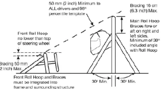
2.2 Illustration of the clearance required above the drivers head. (Sources: Formula SAE Rules (2009))
5
2.3 95th percentile male dimensions as depicted in the 2006 rules (Sources: Formula SAE Rules (2009))
6
2.4 Last year car on track 7
2.5 The 2003 University of Queensland FSAE Chassis (Source : Blessing.J.P ( 2004)).
11
2.6 University of Western Washington's Composite Tub Chassis (Source : Blessing.J.P ( 2004)).
12
2.7 Tensile Strength and Hardness of Plain Carbon Steels (Source : Baker.C.S, (2004)).
14
2.8 Example of frame chassis in torsion 17
2.9 Free body diagram that look from front suspension bay (Source : Riley.W.B and George.A.R. 2002)
18
3.1 Flow chart of PSM I 21
3.2 Flow chart of PSM II 22
3.3 Properties of material is define 34
4.1 Flow chart of design process 37
xv
4.3 3D model of previous chassis 40
4.4 First concept generation 41
4.5 Second concept generation 42
4.6 Third concept generation 42
4.7 Model of main hoop and front hoop 48
4.8 3D Model of new design rear angle view 48
4.9 3D Model of new design front angle view 48
4.10 Top View the new chassis design 50
4.11 Top view of previous chassis design 50
4.12 Side view of new chassis design 51
4.13 Side view of previous chassis design 51
4.14 Front view of new chassis design 52
4.15 Front view of previous chassis design 52
4.16 Final design for the main role hoop 53
4.17 The most complex component the front hoops final design. 55
4.18 The front view of bulkhead 56
4.19 The dimensions of the rear box component of the final design. 57
4.20 Side impact member dimension 58
4.21 Engine bay design dimension 59
5.1 Free body diagram look from side view 61
5.2 Location of applied load and constraint for torsion displacement analysis
64
5.3 Location of applied load and constraint for stress analysis on the overall chassis
64
5.4 Location of applied load and constraint for stress analysis on the front knee box
65
5.5 Location of applied load and constraint for stress analysis on the rear box
66
5.6 Torsional displacement of the previous chassis design 67 5.7 Torsional displacement of the new chassis design 68
5.8 Stress analysis on overall chassis 69
5.9 Stress analysis on the rear box (differential box) 70
xvi 6.1 Flow chart of fabrication process
6.2 The breakdown structure of chassis 74
6.3 The full scale of design is template on trace paper. 75
6.4 The pipes is cut by the disc cutter 76
6.5 Bundle of cutting pipes 76
6.6 The frame is jig by nails and tape with template on the full scale dimension of trace paper
77
6.7 The welding procedure 78
6.8 Grinding procedure to remove surplus of welding 78
6.9 Frame is position in the straight line 79
6.10 Front box is fully constructed 80
6.11 Passenger cell construction 80
6.12 Engine bay construction which using a template and nails in order to hold the pipes
81
6.13 The final design fully constructed 81
6.14 Chassis is check for the sufficient in all areas of the dimensions and construction.
82
6.15 Chassis is check for the sufficient in all areas of the dimensions and construction.
82
6.16 Grinding to remove acces metal of welding 83
6.17 Painting the final product 83
6.18 Weighing the final product 84
7.1 Comparison the ratio of torsional stiffness per weight value with some of Formula SAE’s team
89
7.2 Comparison the torsional stiffness value with some of Formula SAE’s team
89
xvii
LIST OF NOMENCLATURE
σ
von misses = Von misses stressSut = Ultimate tensile strenght Fz = Reaction force
cg = Centre of gravity
L = Length
m = Mass
Mdriver = Mass of driver
Mwheel = Mass of wheel
Mchassis = Mass of chassis
Δy = Displacement at the location of applied load
xviii
LIST OF APPENDIX
NO TITLE PAGE
A Regulation of UTeM’ Formula Varsity 102
B Design dimension of previous UTeM Formula Varsity chassis 120 C Design dimension of new design UTeM Formula Varsity
chassis
1
CHAPTER I
INTRODUCTION
Formula Varsity race car is a competition that is organized by Universiti Teknikal Malaysia Melaka in the quite few years. The competition challenges students to design, analyze, build and race the working model of a racing car in real track condition. The design guidelines were based on the specifications ruled by Formula Varsity 2008 event.
This report deals with the design of the chassis including the method that has been applied in development a formula style race car chassis.
1.10 Objective
2
1.20 Problem Statement
The design of a chassis for a formula style race car contains all the necessary components to support the car and the driver. It must comply with the Formula Varsity rules and regulation. In order to produce a competitive vehicle with optimum chassis performance, many areas need to be studied and tested.
Weight is the main point that affected the performance of the car. Therefore, the main purpose of this project is to design and develop a lightweight chassis. The new chassis is must be lighter than the past year chassis but must maintain the strength of the chassis when load is applied on it.
Some factors that can affect the weight of a vehicle are the types of material used, the diameter or dimension of tubes use to built space frame chassis, and the design geometry of chassis.
This project was started by performing background research required to sustain an accurate database of design criteria. Design criteria is allowed the design process and methodology to be derived as well as and to allow for smooth construction of an efficient and effective space frame chassis. Once construction of the chassis was completed, analyses were conducted to investigate the effects of working loads on the chassis. Finite element analysis was used to simulate the conditions of various load combinations.
1.30 Scope
3
ii. Select suitable material for the chassis through material selection analysis. iii. Evaluate the torsional stiffness for the chassis based on the load analysis. iv. Perform Finite Element Analysis on chassis.
v. Fabricate the new design of Formula Style Race Car chassis.
4
CHAPTER II
LITERATURE REVIEW
2.10 Competition
2.1.0 Competition rules
Adhering to the rules that govern the chassis for the competition is a pivotal part of the research. If one small sub-section rule is not followed, the chassis will disqualified the whole car from the competition.
5
[image:24.612.229.474.163.312.2]The summarized version of the rules can be found in Appendix A. Along with this summary of the rules come some diagrams that relate to the safety aspect of the car as shown in following figure.
Figure 2.1: Illustration of the side impact member’s location. (Sources: Formula SAE Rules (2009))
[image:24.612.200.472.440.590.2]