Abstract—This paper illustrates the design, construction and testing of a looped-tube travelling wave thermoacoustic electricity generator that provides low-cost electrical power for remote and rural areas of developing countries. The system is designed numerically by using a specialized design tool DeltaEC, based on the linear thermoacoustic theory. A commercially available loudspeaker is connected via a 920 mm long side-branch tube to the 5.0 m long one wavelength looped-tube thermoacoustic engine. It is used to convert the acoustic power produced by the engine to useful electrical output. Air at atmospheric pressure is used as working gas to minimize the cost of the construction. The thermal power that drives the engine is supplied by a propane gas burner. It is shown that at an operating frequency of 64.5 Hz, the thermoacoustic generator can produce up to 13 W of electrical power. Results obtained from numerical analysis and experiments are presented and discussed in detail.
Keywords: Electricity generator, Thermoacoustic engine, Thermal-acoustic-electrical power conversion, Linear alternator.
I. BACKGROUND AND INTRODUCTION
More than two billion people around the world who live in the remote and rural areas of developing countries have no access to electricity [1], [2]. A high percentage of the people in these societies use a “three-stone stove” fuelled by biomass as an open stove to cook their food. Consequently, a large fraction of the heat produced is dissipated to the surrounding, while the smoke produced from biomass combustion has very serious effects on their health. At the same time, poor rural communities have no access to electricity and are unable to store vital medicines without refrigeration capabilities. A solution has been proposed in the form of SCORE stove (the Stove for Cooking, Refrigeration
and Electricity supply) to generate electricity from the waste
heat produced during cooking [1]. The smoke released by the stove is contained and driven away from the dwelling while the Manuscript received March 06, 2013; revised April 20, 2013. This work was supported by EPSRC (UK) under Grants EP/E044379/1 and EP/E044379/2 and the Libyan Government PhD scholarship to Mr Abdoulla, who would like to gratefully acknowledge this support. Dr Kang would like to gratefully acknowledge the support from China Scholarship Council during her stay at the University of Leicester.
Kalid Abdoulla is a PhD student at Department of Engineering, University of Leicester, University Road, Leicester LE1 7RH, UK.
Huifang Kang is with School of Mechanical and Vehicular Engineering, Beijing Institute of Technology, Beijing, 100081, China
Artur J. Jaworski, corresponding author, is with Department of Engineering, University of Leicester, University Road, Leicester LE1 7RH, UK (phone: +44 (0) 1162231033; fax: +44 (0) 1162522525; email: [email protected]).
waste heat energy produced by biomass burning is used for producing electricity. This can be used for lighting, powering radios, charging mobile phones or re-charging batteries for later use. Importantly, the main objectives of SCORE are to improve the quality of life, health and economic factors in the poor communities of developing countries by developing a low-cost electricity generator. Thermoacoustic technologies have been selected to achieve the targets of SCORE project due to their simplicity in constructing the practical devices, and potential of converting heat (thermal) power to electricity at low cost. It should be noted that in another application (not discussed here, but in a separate paper at the WCE2013), thermoacoustic technologies are also shown to provide refrigeration capabilities.
II. THERMOACOUSTIC TECHNOLOGIES
Thermoacoustic phenomena are essentially understood as thermodynamic interactions between a sound wave and solid material in the presence of temperature gradient in the direction of sound wave propagation. The first qualitative explanation was given by Lord Rayleigh [3]: “if heat be given to the air at the moment of greatest condensation, or be taken from it at the moment of greatest rarefaction, the vibration is encouraged”. The theoretical foundations of a quantitative theory were first proposed by Rott [4], [5] who derived the wave and energy equations for sound propagating along a temperature gradient in a channel.
The principles outlined above can be applied for constructing thermoacoustic (TA) devices (engines or coolers) which have advantages of low cost and low maintenance, due to the lack of moving parts in the execution of the thermodynamic cycle. In essence, TA engines convert thermal into acoustic energy, while TA coolers use the acoustic energy input to deliver refrigeration capabilities. The acoustic/electric conversion needed in either type of the devices is usually provided by an electro-dynamic transduction mechanism. TA systems typically use high efficiency flexure bearing supported linear alternators.
Although, the linear alternators perform the acoustic-to-electric power conversion with high efficiency and reliability, the high cost of these devices would eliminate the chance of building inexpensive systems targeted by SCORE project. However, in less demanding applications commercially available audio loudspeaker can also be good candidates for producing electricity at a fraction of cost [6].
A variety of thermoacoustic engines have been designed and tested in order to utilize the thermoacoustic effects to produce useful acoustic power. The mechanism of the thermoacoustic
Travelling
:
ave
7
hermoacoustic
(
lectricity
*
enerator for
5
ural
$
reas
8
sing a
6
ide-branch
A
lternator
A
rrangement
engines mainly depends on providing a temperature gradient in a porous medium sandwiched between a cold heat exchanger (CHX), and a hot heat exchanger (HHX). Based on the acoustic pressure and velocity phase difference (sound wave characteristics) in the thermoacoustic engine, the porous material can be a stack in standing wave thermoacoustic engine or a regenerator in travelling wave thermoacoustic engine. A large scale standing wave thermoacoustic engine was designed and tested by Swift [7]. The engine produced up to 630 W of acoustic power to the external acoustic load at mean pressure of 13.8 bar, with helium used as a working gas. It achieved the thermal-to-acoustic conversion efficiency of 9%. There have been many studies to improve the performance and the thermal efficiency of the standing wave engines. However, their thermal efficiency (acoustic power produced-to-heat input) is typically limited to 20%. The low efficiency is due to working medium undergoing an irreversible thermodynamic cycle caused by an imperfect heat transfer between the gas and the solid material, needed to implement the required time delay to sustain the oscillation [8].
Ceperley [9], [10] realised that if a regenerator is placed within the travelling sound wave, the heat transfer between the gas parcels and the solid material experiences a Stirling-like thermodynamic cycle. A further work was done by Yazaki et al. [11] to prove the theory by building a first looped-tube travelling wave engine. However, both Ceperley [9] and Yazaki [11] could not achieve high engine efficiencies due to low acoustic impedance of the working gas, which caused large viscous losses resulting from high acoustic velocities.
Backhaus and Swift [12], [13] designed and tested a thermoacoustic Stirling engine having a torus and a standing wave resonator. The engine produced a high acoustic power by utilising a reversible Stilling cycle in the regenerator and reducing the acoustic dissipation by increasing the acoustic impedance. Although, the comparable thermal to acoustic efficiency of 30% was achieved by the engine, the long standing wave acoustic resonator dissipated much of the acoustic power produced at the regenerator [14].
The thermoacoustic travelling wave engines having looped tube are considered relatively efficient due to the travelling wave having a zero phase difference between the oscillating pressure and velocity controlling the acoustic field in the engine. The problems of acoustic impedance are addressed by an increase in the cross-sectional area of the engine core (CHX, regenerator, HHX) to reduce the viscous losses by reducing the velocity locally [9], [15]-[17]. However complications arise when low impedance alternators (such as audio loudspeakers) are introduced into the loop. One of the design strategies is therefore introduction of adjustable-length side-branches (stubs) to improve the acoustic impedance matching [18]-[20].
However, the thermoacoustic electricity generator developed previously by the team in the University of Leicester (with an alternator “in line” within the loop) could produce the maximum electrical power of 11.6 W at a thermal-to-electric efficiency of less than 3%. It also used an electric heater as a hot heat exchanger which did not fully demonstrate the operation of the rig using heat input from combustion processes. The current work addresses some of the shortcomings of previous work. For achieving higher
performance of the looped tube travelling wave engine, Kitadani et al. [21] suggested that connecting the resonance tube to the loop at the anti-node of the sound pressure field can increase the thermal-to-acoustic power efficiency by around 20 times by decreasing the phase difference between the acoustic pressure and velocity.
This paper describes the design, construction, and testing of a looped-tube traveling wave electricity generator having an alternator connected to the loop by a side branched resonance tube and being powered by the combustion processes; here propane burner is used to simulate biomass combustion.
III. DELTA-EC MODELLING
In order to perform a more detailed analysis, a specialized design tool referred to as DeltaEC (Design Environment for Low-amplitude ThermoAcoustic Energy Conversion) and developed by Los Alamos National Laboratory is employed [22]. Its calculation capabilities and precision in modeling thermoacoustic devices have been validated by many researchers [12], [23]. DeltaEC solves the one-dimensional wave equation based on the usual low-amplitude acoustic approximation. A solution to the appropriate one-dimensional wave equation is found for each segment, with pressures and volume flow rates matched at the junctions between segments. In stacks, the wave equation solution is found simultaneously with that of the energy-flow equation in order to find the temperature profile as well as the acoustic pressure. The energy flow through stacks is determined by temperatures and/or heat flows at adjacent heat exchangers.
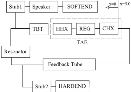
In the current work, DeltaEC is used to simulate the acoustic field and the acoustic power flow in the thermoacoustic device under study. A block diagram of the system is shown in Fig. 1. An x-coordinate is set up for convenience of calculations and analysis of the system. Here, the right side of the cold heat exchanger (CHX) of the thermoacoustic engine (TAE) is set as the origin of the coordinate (x = 0 m), while the positive direction is then
pointing towards the regenerator (cf. Figs. 1 and 2).
TBT HHX REG CHX
Resonator
Speaker SOFTEND Stub1
Feedback Tube
Stub2 HARDEND TAE
[image:2.595.317.533.533.684.2]x=0 x=5.0
Fig. 1. The block diagram of the segments in DeltaEC model: (1) clod heat exchanger (AHX), (2) regenerator (REG), (3) hot heat exchanger (HHX), (4) thermal buffer tube (TBT), (5) the first stub of which the speaker is located in the end (Stub1), (6) the tube between the first stub and the second stub (Resonator), (7) the feedback tube, (8) the second stub (Stub2).
The first T type junction is after the thermal buffer tube (TBT) with the coordinate (x = 0.79 m), while the second T
type junction is after segment called “Resonator” with (x =
“Feedback Tube” which joins the beginning of the loop (i.e. x
= 0 m is equivalent to x = 5 m). The simulation for the
thermoacoustic device is from the origin along the established coordinate to each segment, with pressures and volumetric velocities matched at the junctions between segments.
IV. EXPERIMENTAL APPARATUS
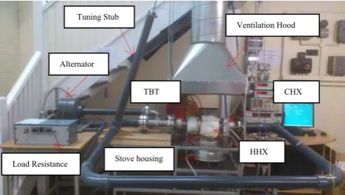
[image:3.595.47.294.362.479.2]The experimental set up is shown schematically in Fig 2; Fig. 3 shows the practical laboratory implementation. Along the engine loop there are: cold heat exchanger (CHX), stacked screen regenerator (REG), hot heat exchanger (HHX), thermal buffer tube (TBT), side branched alternator (ALT), side branched matching stub, and feedback pipe. The total length of the loop is around 5.0 meters, the alternator side branch pipe is around 920 mm, and the side branch stub is around 450 mm, at working frequency of around 64.5 Hz. The cold heat exchanger is made out of an aluminum block, which is 60 mm long and has 110 mm diameter. Gas passages are made in the form of 430 holes with the diameter of 3 mm, drilled parallel to the heat exchanger’s centre-line. 20 holes with the diameter of 6 mm are drilled perpendicular to the heat exchanger axis to pass cooling water. The porosity of the cold heat exchanger is about 32%.
Fig. 2. Schematic drawing of the experimental thermoacoustic generator.
Fig. 3. Photograph of the tested thermoacoustic generator.
The regenerator is made out of stainless screen disks (110 mm in diameter), with the mesh number 34 and the wire diameter 0.16 mm. 72 discs have been piled up in a stainless steel can which has a wall thickness of 2 mm. The disks form a 23 mm long regenerator. Consequently, the calculated porosity and hydraulic radius are 82% and 196 μm, respectively. Two Type-K thermocouples (TC-Direct model 408-119) are installed at the two ends of the regenerator. They monitor the temperature difference between the two ends of the regenerator as shown in Fig. 2.
The hot heat exchanger has a shell-and-tube configuration and is connected to the thermal buffer tube. It has a bundle of 37 stainless steel tubes with an inside diameter of 8 mm, outside diameter of 10 mm, and a length of 160 mm. The centre-to-centre distance between two neighboring tubes is 15 mm on a triangular distribution. The porosity of the hot heat exchanger is about 19.6%. The flue gas from the gas burner flows around the outer surface of the bundle of tubes, whereas the thermoacoustic gas oscillates inside these tubes. Three Type-K thermocouples are placed in three tubes to monitor the solid temperature of the tube wall and the approximate positions of these thermocouples are schematically shown in Fig. 2.
As seen from Figs. 2 and 3, after the hot heat exchanger, there is a thermal buffer tube, which is simply a section of stainless steel pipe (ID=110 mm) with a length of 178 mm, and a wall thickness of 2 mm. The 110 mm diameter buffer tube connects to a smaller thermal buffer tube via a short transition cone, which reduces the diameter from 110 mm to 54 mm over a distance of 54 mm. The small diameter buffer tube is around 160 mm long and has the internal diameter of 54 mm (a section of standard stainless steel 2-inch tube, with 2.77 mm wall thickness). To simplify the design, the thermal buffer tube is not thermally insulated, and therefore it can be cooled by the ambient air. A “T” section is connected to the thermal buffer tube as shown in Figs. 2 and 3 using flanges. About 15 centimeters away from the end flange of TBT, a branch pipe is connected to the loop. The branch pipe is about 92 centimeters in length, and the alternator is installed at the end. A “stub” tube (450 mm in length) is connected to the resonator through another T-junction to improve the impedance matching between the branched alternator and the engine.
Part of the produced acoustic power is extracted by the branched alternator. Here, from the economic point of view, a standard audio loudspeaker, 8-inch B&C 8BG51 subwoofer, is utilized as the alternator due to its relative high transduction efficiency and low impedance according to the selection criteria summarized in [23]. Its parameters have been measured as listed in Table I.
The feedback pipe is made of standard 2-inch PVC pipe and 90 bends (Class E, OD: 60.3 mm, thickness 4.5 mm) instead of a metal pipe, to reduce cost. As shown in Fig. 2, five pressure transducers (microphones) have been installed, marked as P1 to P5, to measure the acoustic oscillations within the engine. A laser displacement sensor (Keyence LK-G152) is installed at the back side of the alternator to measure the displacement of the alternator diaphragm. It has a standoff distance of 150 mm, and a measuring range of ±40 mm. The sampling frequency is 50 kHz and the resolution is 0.5 m.
Using two-microphone method [8], the measurements from P1 and P2 can estimate the acoustic power flow to the feedback pipe, whereas the measurements from P3 and P4 can estimate the acoustic power flow back to the cold heat exchanger. The acoustic power extracted by the alternator can be estimated by the laser displacement sensor and microphone P5. A high power variable resistor is adopted as an electrical load for the alternator to extract electrical power. The voltage difference and the current flowing through the Ventilation Hood
Tuning Stub
TBT
HHX CHX Alternator
[image:3.595.47.293.507.646.2]load resistor are measured using a standard voltmeter (with a resolution of 0.001 V) and ammeter (with a resolution of 0.01 A).
V. RESULTS AND DISCUSSION
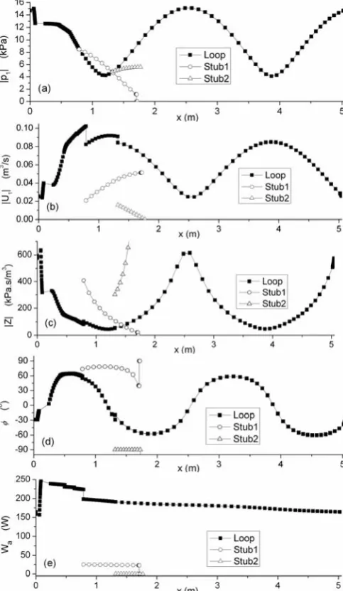
The simulation results discussed in this section are based on the final design of the prototype. The calculation was carried out under the conditions as follows: air is used as working gas, the mean pressure is 1bar, the length of the stub is 450 mm, the load resistance is 12 Ω, and the temperature difference between the two ends of the regenerator is maintained at 430 K. The calculation results of the distributions of the acoustic power flow and the acoustic field
in the system are shown in Fig. 4.
Fig. 4a shows the pressure amplitude distribution along the system. There are two maxima and two minima of pressure amplitude along the loop and one sharp pressure drop. The pressure drop is caused by the flow resistance of the regenerator. The pressure amplitude changes smoothly along all other parts. The pressure distributions are different in two stubs. The reason for this is that two stubs with different ends (the first stub is open end, while the second stub is closed end) reduce to different boundary conditions: p1 = 0 for the open end, and U1 = 0 for the closed end). Additionally, results confirmed that the open end of the branch resonator with the alternator becomes the node of the sound pressure and the closed end of the tuning stub becomes the antinode of the sound pressure.
Fig. 4b shows the distribution of volumetric velocity along the system. There are also two maxima and two minima along the loop. One maximum is on the first T type junction where
x = 0.79 m, and the other is near the end of the feedback tube
where the minimum of the pressure amplitude is located. One minimum of the volumetric velocity is at the cold end of the regenerator, while the other is close to the middle of the feedback tube. The small volumetric velocity within the regenerator is preferred to avoid high viscous dissipation, which is one of the design strategies behind the current concept. It can also be seen that the volumetric velocity
increases significantly along the regenerator. This is due to the sharp temperature gradient along the regenerator. Furthermore, at the location of the stub, there is a sudden decrease of the volumetric velocity. Along all other parts, the volumetric velocity changes smoothly. Additionally, results confirmed that the open end of the branch resonator with the alternator becomes the antinode of the particle velocity, and the closed end of the tuning stub becomes the node of the particle velocity.
Fig. 4c shows the acoustic impedance along the system. It can be seen that the acoustic impedance is highest at the cold end of the regenerator. The impedance drops quickly because the pressure amplitude decreases (see Fig. 4a) while the volumetric velocity increases sharply from the cold to the hot end of the regenerator (see Fig. 4b). The stub introduces a sudden increase of the acoustic impedance along the loop. This is because the pressure amplitude at the stub junction is constant, while the volumetric velocity has been shunted partly to the stub. From Fig. 4c, one can also find that the alternator is very close to the minimum of acoustic impedance. This is also a carefully designed feature of the device, introduced to obtain a sufficient volumetric velocity to drive the alternator to the maximum excursion which subsequently maximizes the electrical power output.
Fig. 4d shows the phase difference between pressure and velocity oscillation along the system. It can be found that the regenerator works in the region of (-12 < < 28). It is
indicated that the regenerator can realize the conversion from heat to acoustic energy by both the standing-wave and travelling-wave [24]. The phase difference in the first stub is positive, while the phase difference in the second stub is negative. The reason is that the open end of the first tube is the node of the sound pressure and the closed end of the second tube is the node of the sound velocity [25]. From Fig. 4d, one can also find that the phase difference in first stub is closer to zero than that in second stub. The reason is that there is more acoustic power transferring into the first stub than that in second stub (see in Fig. 4e), and subsequently the traveling wave ratio on which the acoustic power transfer relies in the first stub is more than that in the second stub. It leads to the phase difference in first stub being closer to zero, and then changing to 90o after the acoustic power is extracted in the speaker [25].
Fig. 4e shows the acoustic power flow along the system. It can be found that around 160.8 W of acoustic power is fed into the cold heat exchanger which dissipates around 2.2 W. The remaining 156.6 W is fed into the cold end of the regenerator. Within the regenerator, the acoustic power is amplified to around 246.4 W which is the level of acoustic power flowing out from the hot end of the regenerator. The hot heat exchanger and thermal buffer tube dissipate around 14.2 W. The acoustic power of 25.0 W enters the first stub and the alternator extracts about 22.8 W of acoustic power. In this simulation, the alternator produces 13.6 W of electricity. As mentioned above, the required input heat is 560.8 W for this case. Therefore, the calculated thermal-to-acoustic efficiency is 23.0%, acoustic-to-electric efficiency is 59.7%, and thermal-to-electric efficiency is 3.5%. The work done in the experiments is concentrating on testing the performance of the generator by altering the temperature difference of the two sides of the regenerator at stub length of 450 mm and load resistance of 12 Ω. In addition, another set of experiments was done in this work at the onset temperature of TABLEI
SPECIFICATIONS OF THE LOUDSPEAKER (ALTERNATOR)[23]
Symbol Nominal Measured Standard deviation
F 52 40.49 ± 0.4%
Bl 11.8 11.09 ± 0.24%
Le 0.5 0.48 ± 2%
Re 5.1 5.16 ± 0.1%
Mm 35 27.4 ± 0.7%
Km 3736 1773 ± 1.48%
Rm 0.93 1.23 ± 1.31%
X +/-6.5
Aalt 220
F= Frequency (Hz), Bl= Force factor (N.A-1), Le= Electric inductance
(mH), Re= Electric resistance (Ω), Mm=Moving mass (g), Km=Stiffness
(kg.s-1),
the engine with variety of load resistances. Having the loudspeaker connected to the loop by side branch tube the thermoacoustic generator starts to oscillate when the temperature difference between the ends of the regenerator is 240 K.
Fig. 4. The calculation results of the distributions of the acoustic power flow and the acoustic field in the system. (a) Pressure amplitude; (b) Volumetric velocity; (c) Acoustic impedance; (d) Phase angle; and (e) Acoustic power
flow.
[image:5.595.312.542.112.287.2]Fig. 5 shows the influence of the temperature difference of two ends of the regenerator on the electric power produced by the alternator. It can be seen from the graph, that the electricity increases linearly to achieve maximum 13 W of electric power at temperature difference around 430 K across the regenerator. It also can be shown in the graph that DeltaEC calculations and measurements have the same tendency of a linear increase as the temperature difference of the regenerator increases. Results show that the measured and predicted vaules of the electricity agree at higher temperature differences whereas a considerble discrepancy occures at lower temeprature differences.
Fig. 6 shows the impact of the temperature difference between the hot and cold side of the regenerator on the coil displacement of the alternator. It is shown from the graph that the coil displacement increases as the difference between the
[image:5.595.49.291.124.540.2]cold and hot temperature increases. The calculated and the measured displacements show a good agreement at temperature difference of 430 K whereas the calculated displacement exceeds the measurements at lower temperatures.
Fig. 5. The relationship between the temperature difference of two ends of the regenerator and the electricity output.
Fig. 6. The impact of the temperature difference of two ends of the regenerator and the coil displacement of the alternator.
Fig. 7 shows the effects of the temperature difference across the regenerator on the acoustic power consumed by the alternator. From the chart it can be seen that there is good agreement between the predictions and the measurements specifically at high temperature differences.
[image:5.595.314.539.322.485.2] [image:5.595.311.542.585.754.2]VI. CONCLUSION
This paper describes the design, construction and testing of a low cost looped-tube travelling wave thermoacoustic engine that converts heat power to acoustic power whereas a commercially available low cost loudspeaker is connected to the loop by a side branch pipe to convert the acoustic power to electricity. The prototype designed in this paper simulates a device that can be driven by the solar energy, waste heat or the biomass combustion in the cooking stove in remote and rural areas to drive a linear alternator that produces electricity. The preliminary results at optimum stub length of 450 mm and load resistance of 12 Ω show that there is a satisfactory agreement between the experimental readings and the calculations of DeltaEC model at higher temperature differences between the two ends of the regenerator. However, there is also a considerable disagreement between calculations and measurements when the temperature difference starts to decline. In contrast, when the thermoacoustic engine starts to vibrate, results show huge divergence between calculations and measurements at different load resistances.
Additionally, as the experimental work shows, encouraging results where the prototype of the thermoacoustic generator powered by flue gas from propane gas burner can produce up to 13 W of electricity using commercial loudspeaker are obtained. Hence the thermoacoustic technology can be promising to achieve and build other devices that produce higher levels of electricity.
Consequently, the development of such prototype could lead to larger scale devices, able to consume higher heat input, or perhaps having several stages of thermoacoustic engines where lower temperature grade heat sources can be utilized.
A further work is being implemented to develop a travelling wave thermoacoustic electric generator that can produce up to 100 W of electric power to the applications in remote and rural area. The strategy considered in this development is to utilize sources of low-grade temperatures to power two stages of a looped-tube travelling wave engine and using a low-cost loudspeaker as alternator in series with loop to convert the acoustic power produced to electric power.
REFERENCES
[1] www.score.uk.com
[2] www.undp.org
[3] L. Rayleigh, “The explanation of certain acoustical phenomena,”
Nature, vol. 18, pp. 319–321, 1878.
[4] N. Rott, “Damped and thermally driven acoustic oscillations in wide and narrow Tubes,” Z Angew Math Phys, vol. 20, pp. 230–243, 1969
[5] N. Rott, “Thermally driven acoustic oscillations, part III: Second-order heat flux,” Z. Angew. Math. Phys, vol. 26, pp. 43-49, 1975.
[6] Z. Yu, P. Saechan and A. J. Jaworski, “A method of characterising performance of audio loudspeakers for linear alternator applications in low-cost thermoacoustic electricity generators,” Applied Acoustics, vol. 72, no. 5, pp. 260-267, 2011.
[7] G. W. Swift, “Analysis and performance of a large thermoacoustic engine,” Journal of the Acoustical Society of America, vol. 92, no. 3,
pp. 1551-1563, 1992.
[8] G. Swift, Thermoacoustics: A Unifying Perspective for some Engines and Refrigerators. Los Alamos national laboratory, fifth draft, May 2001, pp. 13-36.
[9] P. H. Ceperley, “A pistonless Stirling engine – The traveling wave heat engine,” J. Acoust. Soc. Am, vol. 66, no. 5, pp. 1508-1513, 1979.
[10] P. H. Ceperley, “Gain and efficiency of a short travelling wave heat engine,” Journal of the Acoustical Society of America, vol. 77, no. 3,
pp. 1239–1244, 1985.
[11] T. Yazaki, A. Iwata, T. Maekawa, and A. Tominaga, “Travelling Wave Thermoacoustic Engine in a Looped Tube,” Physical Review Letters, vol. 81, no. 15, pp. 3128-3131, 1998.
[12] S. Backhaus, and G. W. Swift, “A thermoacoustic-Stirling heat engine: Detailed study,” Journal of the Acoustical Society of America, vol. 107,
no. 6, pp. 3148-3166, 2000.
[13] S. Backhaus, and G. Swift, “A thermoacoustic Stirling heat engine,”
Nature, vol. 399, pp. 335-338, 1999.
[14] Z. Yu, and A. J. Jaworski, “Impact of acoustic impedance and flow resistance on the power output capacity of the regenerators in travelling wave thermoacoustic engines,” Energy Conversion and Management,
vol. 51, pp. 350–359, 2010.
[15] K. T. Feldman, “Review of the literature on Rijke thermoacoustic phenomena,” Sound Vib, vol. 7, no. 1, pp. 83–89, 1968.
[16] A. A. Atchley, “Standing wave analysis of a thermoacoustic prime mover below onset of self-oscillation,” J Acoust Soc Am, vol. 92, no. 5, pp. 2907-2914, 1992.
[17] H. B. Ke, Y. W. Liu, Y. L. He, Y. Wang, and J. Huang, “Numerical simulation and parameter optimization of thermoacoustic refrigerator driven at large amplitude,” Cryogenics, vol. 50, pp. 28-35, 2010.
[18] Z. Yu, A. J. Jaworski, and S. Backhaus, “A low-cost electricity generator for rural areas using travelling-wave looped-tube thermoacoustic engine,” Power and Energy, vol. 224, pp. 787-795,
2010.
[19] Z. Yu, and A. J. Jaworski, “Designing a low-cost thermoacoustic electric generator and the experimental verification,” presented at the ESDA10 Conference, Istanbul, Turkey, July. 12-14, 2010.
[20] Z. Yu, A. J. Jaworski, and S. Backhaus, “Travelling-wave thermoacoustic electricity generator using an ultra-compliant alternator for utilization of low-grade thermal energy,” Applied Energy, vol. 99,
pp. 135-145, 2012.
[21] Y. Kitadani, S. Sakamoto, K. Sahashi, and Y. Watanabe, “Basic study for practical use of thermoacotic electric generator system,” presented at the ICA 2010 Congress, Sydney, Australia, August. 23-27, 2010. [22] W.C. Ward and G.W. Swift, “Design environment for low-amplitude
thermoacoustic engines,” Journal of the Acoustical Society of America,
vol. 95, no. 6, pp. 3671-3672, 1994.
[23] H. F. Kang, Q. Li, and G. Zhou, “Heat driven thermoacoustic refrigerator based on travelling-standing wave,” Energy Conversion and Management, vol. 51, pp. 2103-2108, 2010.
[24] http://www.bcspeakers.com/
[25] H. F. Kang, Q. Li, and G. Zhou, “Thermoacoustic effect of travelling–standing wave,” Cryogenics, vol. 49, pp. 112-119, 2009.