City, University of London Institutional Repository
Citation:
Kovacevic, A. and Stosic, N. (2013). Grid Generation for Screw Compressors
with Variable Geometry Rotors. International Journal of Aerospace and Lightweight
Structures, 3(2), doi: 10.3850/S2010428613000603
This is the accepted version of the paper.
This version of the publication may differ from the final published
version.
Permanent repository link:
http://openaccess.city.ac.uk/15299/
Link to published version:
http://dx.doi.org/10.3850/S2010428613000603
Copyright and reuse: City Research Online aims to make research
outputs of City, University of London available to a wider audience.
Copyright and Moral Rights remain with the author(s) and/or copyright
holders. URLs from City Research Online may be freely distributed and
linked to.
City Research Online: http://openaccess.city.ac.uk/ [email protected]
GRID GENERATION FOR SCREW COMPRESSORS WITH VARIABLE GEOMETRY ROTORS
AHMED KOVACEVIC*, SHAM RANE and NIKOLA STOSIC
Centre for positive displacement compressor technology, City University London, Northampton Square, London, EC1V 0HB, United Kingdom
Received 16November2013 Revised Day Month Year
An algebraic grid generation algorithm is presented in this paper which enables the performance of twin screw compressors with variable rotor geometry to be predicted, by means of Computational Fluid Dynamics (CFD). It is based on a method, previously developed by the authors, for compressors with standard uniform pitch rotors and constant cross-section profile, which has now been extended to include rotors with variable pitch and/or variable profile. By its use with the commercial CFD solver ANSYS CFX, it has been possible to obtain performance predictions for three variants of an oil-free 3/5 screw compressor, namely uniform helical rotors, variable pitch rotors and variable profile rotors. The variable pitch and variable profile rotors achieve steeper internal pressure rise and a larger discharge area for the same pressure ratio. Variable pitch rotors also showed lower leakage rates due to reduced sealing line length in the high pressure domain. This grid generating procedure advances the ability to evaluate both existing and novel compressor configurations.
Keywords:Algebraic Grid Generation; Computational Fluid Dynamics; Twin Screw Compressor; Variable Pitch Rotors; Variable Profile Rotors.
1. Introduction
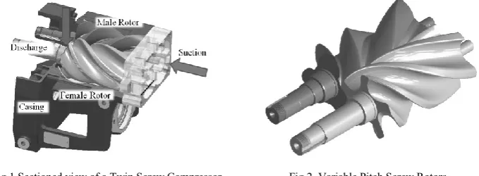
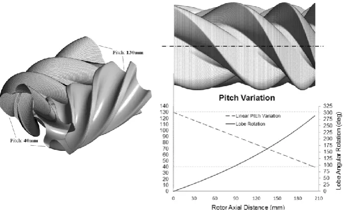
Twin screw compressors contain helically lobed rotors with profiles that optimize the compression process. The pitch of screw compressor rotors is defined as the axial distance between the tips of consecutive lobes. This is normally constant along the rotor length. Fig.1shows a CAD model of a twin screw compressor consisting of the compression chamber formed between the helical rotors and casing. Such a domain includes the main chamber, the leakage paths, and the rotor ports. Rotors with variable pitch were patented by Gardner in 1969 but are rarely used due to the lack of cost effective manufacturing techniques for their production.Fig.2 shows a pair of twin screw rotors with variable pitch. It has been shown in the literature that for the same rotor lengths, diameter, wrap angles and lobe profiles, variable pitch rotors can provide a higher pressure ratio and larger discharge port opening areas than the equivalent rotors of constant pitch with reduced throttling losses [Gardner, 1969]. Even higher compression ratios could be achieved when the rotors are of variable diameter.
*City University London, Tait Building, CG07, School of Engineering and Mathematical Sciences,
Twin screw machines are today often analysed by the use of Computational Fluid Dynamics (CFD). The prerequisite for successful CFD analysis is appropriate space discretization by a suitable numerical grid. Three main mathematical methods are used to generate such grids, namely algebraic methods, differential methods and variational methods, as described in Eiseman [1992], Liseikin [1998, 1999], Samareh and Smith [1992], Shih et. al. [1991], Soni [1992] and Thompson [1999]. The use of general purpose grid generators for screw compressors has been found to be inadequate and only customized grid generation programs have been found to be suitable for twin screw compressor applications[Kovacevic et. al., 2007, Prasad, 2004,Voorde et. al., 2004, Rane et. al., 2013].
Fig.1.Sectioned view of a Twin Screw Compressor Fig.2. Variable Pitch Screw Rotors
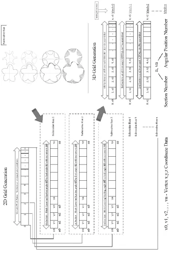
[image:3.595.156.435.489.643.2]Kovacevic et. al. [2000, 2002, 2004, 2005 and 2007] have successfully used an algebraic grid generation method to produce a numerical mesh for twin screw machines with constant pitch rotors. This has been implemented in a customized program called Screw Compressor Rotor Grid Generator. Fig.3 shows an example of one cross-section in a grid produced by this method.
2. Grid Generation for variable geometry rotors
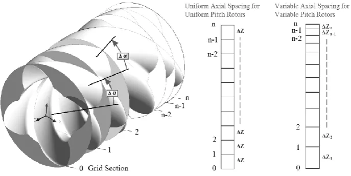
[image:4.595.123.467.272.444.2]Rotors with a uniform pitch and a constant rotor profile have a fixed relationship between the lead and rotor rotation angles. This allows for the numerical grids generated in one cross section at different angular positions in time to be used conveniently for spatial definition of rotors along the rotor axis. The challenge in generating a numerical grid for variable lead rotors is in establishing the relationship of the axial distance between consecutive cross sections and the angular rotation of the rotor. Uniform rotation does not correspond to the uniform axial spacing of cross sections in variable pitch rotors. Fig.4 shows the difference in grid spacing for constant and variable pitch rotors.
Fig.4. Cross sectional spacing for uniform and variable pitch rotors
The rotor pitch is usually constant. However it can also change linearly, non-linearly or in steps. The former is often used for screw vacuum pumps while the latter is applied in some car superchargers. The change in the pitch can be expressed through following equations:
rotors form a conjugate pair in each cross section. Therefore each section can be calculated independently using its specific rotor profile.
An example of a constant rotor profile with variable pitch rotors is shown in Fig. 7 while the grid for variable rotor geometry and uniform pitch is shown in Fig. 8.
3. CFD Analysis
Numerical analysis was carried out by use of the ANSYS CFX solver in order to validate the grid generation approach for a variable rotor profile and to study the performance of compressors with various configurations. The male rotor had 3 lobes with 127.45mm outer diameter, L/D ratio 1.6 and a wrap angle Φw of 285°. The female rotor had 5 lobes and the rotor center distance was 93mm. Both rotors had rack generated ‘N’ profiles. The compressor speed was 8000 rpm with assumed pressure ratios of 2:1 and 3:1.
3.1. Case description
Three test cases were calculated.
Case 1. Uniform pitch and uniform profile rotors with built in volume index Vi of 1.8.
[image:6.595.204.403.409.499.2]Case 2. Uniform Pitch and Profile rotors with a reduced discharge port opening area to give a built in volume index Vi of 2.2. In this case, the compression chamber is exposed to the discharge pressure relatively late in the cycle as shown in Fig. 6 and allows for further pressure build up in the chambers.
Fig. 7. Variable pitch grid – 3/5 ‘N’ rotors with Case 3
Case 3. Variable pitch with uniform profile rotors and built in volume index Vi> 1.8. The Suction side pitch was 130mm and Discharge side pitch was 40mm. The wrap angle of Φw 285° was maintained as shown in Fig. 7.
Fig. 8. Variable profile grid – 3/5 ‘N’ rotors with Case 4
3.2. Simulation description
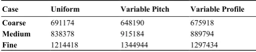
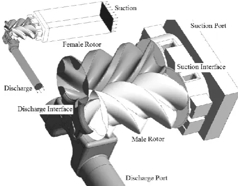
Each rotor configuration was analyzed with three levels of successive grid refinements. Table 1 shows the number of computational nodes in each case. The stationary compressor ports were meshed by the use of a commercial grid generator. Fig. 9 shows the different parts of the numerical model and the grid refinement is shown in Fig. 10.
[image:8.595.163.423.472.525.2]The numerical solver used for the study was the ANSYS CFX [2011], which uses a vertex-based Finite Volume Method and solves for momentum and continuity in a pressure coupled algorithm iteratively. All the generated grids are passed to the solver in the model setup and during the solution the rotor domain grids are updated for every time step, by external subroutines. The space conservation law is retained during this grid motion by modification of the governing equation, as described by Ferziger and Peric [1996]. The solver was set with a Higher Order advection scheme and a Second Order Backward Euler temporal discretization.
Table 1. Grid refinement shown as number of computational nodes.
Case Uniform Variable Pitch Variable Profile Variable Pitch Variable Profile
Coarse 691174 648190 675918
Medium 838378 915184 889794
Fig. 9. Twin screw compressor working chamber domains
Fig. 10. Different levels of grid refinement shown for one cross section
The tetrahedral meshes of the ports and the hexahedral meshes of the two rotor subdomains are connected by non-conformal interfaces in the solver.
[image:9.595.128.469.348.553.2]coefficient loops for every time step were set at 10. During the solution, the rms residuals for all the time steps were between 1.0x10⁻³ and 5.0x10⁻³ for the momentum equation and below 1.0x10⁻³ for the continuity and energy equations. The calculations were run until cyclic repetition of the flow and pressure characteristics was identified at the boundaries. Each case was calculated with both a Laminar and an SST k-Omega Turbulence model.
3.3. Results and Discussion
3.3.1. Compression characteristics
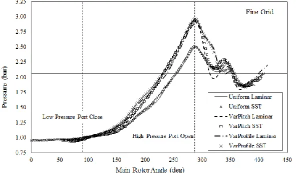
Fig. 11 shows the compression characteristic of cases 1, 3 and 4 for one full cycle on fine grids with a discharge pressure of 2.0 bar. With uniform rotors the maximum pressure goes up to 2.5bar and with variable geometry rotors the maximum pressure goes up to 3.0bar. Case 3, with a variable rotor pitch, and Case 4, with a variable rotor profile, have a steeper rise in internal pressure than Case 1 which has constant rotor geometry. The highest peak pressure is achieved with the variable pitch rotors. For a discharge pressure of 2.0bar this internal pressure rise is the result of over-compression.
Fig. 11. Indicator diagram for Laminar and Turbulent cases with fine grid. Discharge pressure 2.0 bar
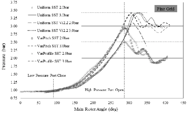
[image:10.595.150.446.365.538.2]Fig. 12. Indicator diagram for cases calculated on fine grid with turbulence models. Discharge pressure 2.0bar and 3.0 bar
3.3.2. Discharge Port Area
Fig. 6 shows how the discharge port area decreases when the Vi is increased to 2.2. In Case 2, with uniform pitch and a reduced discharge port opening area, the internal pressure rises to about 3.1bar before exposure to a discharge pressure of 2 bar, as shown in Fig. 12 . This pressure rise was close to that with variable geometry rotors at about 3.0bar, for which the opening area was 22% higher. It should be noted that a larger discharge area for a comparable pressure rise reduces throttling losses in the compressor.
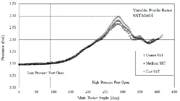
[image:11.595.128.467.565.689.2]3.3.3. Influence of grid refinement
Fig. 13 shows the effect of grid refinement on the prediction of integral quantities such as the mass flow rate, indicated power and specific power for cases 1, 3 and 4 with 2 bar discharge pressure. The mass flow rate showed an increase with grid refinement in all cases.
Fig. 14. Indicator diagram for cases 4 showing effect of grid refinement with 2.0bar discharge pressure
The difference between each consecutive grid refinement is around 10%. This is because the rotor geometry is captured better with finer grids, thereby resulting in reduced leakage. Similarly, the indicated power increases by 2-5% each time the grid is refined. The increase in the chamber pressure with grid refinement is shown in Fig. 14 for Case 4, with variable profile rotors as an example. In order to achieve a grid independent solution, it will be required to further refine the rotor domain grid in both the circumferential and axial directions.
3.3.4. Influence of Turbulence Model
As shown in Fig. 13, higher mass flow rates are achieved when the turbulence model is applied. The indicated power also increases as a consequence of the increased mass flow. However, the specific power is reduced for all turbulent cases indicating that the influence of turbulence models on mass flow rate prediction is higher than it is on indicator diagram/power prediction.
3.3.5. Sealing Line Length
Table 2 Comparison of Interlobe Sealing Line Length [mm]
Interlobe No Uniform Variable
Pitch Difference
Variable
Profile Difference 1 145.8 175.9 -30.1 158.4 -12.6
2 170.3 164.0 +6.4 162.2 +08.1
3 (part) 069.1 056.8 +12.2 068.4 +00.6
Total 385.2 396.6 -11.5 389.1 -03.9
Fig. 15. Comparison of interlobe sealing line lengths
Table 2 presents the variation in the sealing line lengths between the uniform and variable geometry cases at one of the rotor positions indicating the magnitude of change along the rotors. At the suction end, the sealing line on the variable pitch rotor is 30mm longer but at the discharge end it is 12mm shorter than the sealing line for the constant pitch rotors. This helps to reduce leakage, because the largest pressure difference across the sealing line is at the discharge end. In total, length of the sealing line is reduced by 11mm in the variable pitch rotors. In Case 4 with a variable profile the sealing line at the suction end is 12mm longer but is only slightly different to that of the uniform profile rotor at the discharge end. There is no overall gain in the reduction of sealing line length because the thickness of the gate lobe increases near the discharge end of the rotors.
3.3.6. Blow-hole area
blow-hole area is smaller than for the uniform rotors. In the variable profile rotors, the suction side blow-hole area is nearly the same as that of the uniform rotors but the discharge blow-hole area is smaller than for the uniform rotors. Proportionally, the reduction of blow-hole area towards the discharge side rotors is most pronounced in the case of variable pitch rotors.
Fig. 16. Comparison of Blow-hole area
Table 3 Comparison of Blow-hole area [mm2]
Position Uniform Variable
Pitch Difference %
Variable
Profile Difference %
Suction 9.817 12.49 -27.2 9.83 -0.15
Mid 9.908 9.263 6.51 9.35 5.64
Discharge 9.701 6.562 32.3 9.19 5.29
3.3.7. Overall performance
[image:14.595.151.446.489.558.2]Fig. 17. Comparison of performance at 2.0bar and 3.0bar discharge pressure with fine grid cases
Table 4 Comparison of predicted variable geometry rotor efficiencies
Built-in Volume Index
Volumetric Efficiency %
Adiabatic Efficiency %
2.0 bar 3.0 bar 2.0 bar 3.0 bar
Uniform Vi 1.8 75.30 56.70 54.13 51.73
Uniform Vi 2.2 64.00 55.66 44.06 49.91
Variable Pitch Vi > 1.8 66.20 57.60 46.88 50.99
Variable Profile Vi > 1.8 62.80 55.04 45.16 51.01
Uniform rotors show the highest adiabatic efficiency at 2 bar. But with a Vi of 2.2 the efficiency is lower than that of the variable geometry rotors. At 3 bar, variable geometry rotors with Vi=1.8 have an equal adiabatic efficiency to uniform rotors with the same Vi. This is due to reduced over-compression losses at 3 bar discharge pressure. This gives further indication that variable pitch rotors are more suitable for high pressure applications.
Variable profile rotors show a lower volumetric efficiency than uniform rotors due to the smaller capacity of the machine and also to the higher internal pressure rise. The over-compression before discharge results in a lower adiabatic efficiency except at 3 bar discharge pressure where it is comparable with uniform rotors.
3.4. Conclusion
A 3D grid generation procedure for twin screw compressors with variable pitch and variable profile rotors has been developed and used to carry out performance predictions for such machines using CFD. Examples of grids with variable geometries have been presented and analysis, using them, has shown the flow characteristics within these machines.
[image:15.595.144.453.324.424.2]area, thereby reduced discharge losses, while providing increased volumetric efficiency by reducing the sealing line length in the high pressure zone. Analysis of variable profile rotors also showed a steeper internal pressure rise but there was no reduction in the sealing line length and blow-hole area with this type of rotors. The increase in root diameter of the female rotors with variable profile certainly helps in producing stiff rotors for high pressure applications.
These grid generation developments open new opportunities for further investigation of the flow behavior and improvements in the performance of these machines.
4. Nomenclature
L – Rotor Length
D – Male Rotor Outer Diameter Φw – Male Rotor Wrap Angle α – Male rotor rotation angle
Δα – Increment in Male rotor rotation angle n – Cross section number
Z – Axial distance along the rotors ΔZ – Increment in Axial distance z1 – Number of lobes on the Male rotor z2 – Number of lobes on the Female rotor p – Lead at a given axial position on rotor ps – Starting Lead
pe – Ending Lead Δt – Time Step Size Vi – Built in Volume Index
References
ANSYS 13.0, User Guide and Help Manual, 2011.
Eiseman, P. R. [1992] “Control Point Grid Generation”, Computers & Mathematics with Applications, 24, No.5/6, pp57-67.
Ferziger, J. H. and Peric, M.[1996]Computational Methods for Fluid Dynamics, (Springer, Berlin, Germany),ISBN 978-3-540-42074-3.
Fleming, J. S., Tang, Y. and Cook, G.[1998]“The Twin Helical Screw Compressor, Part 1: Development, Applications and Competitive Position, Part 2: A Mathematical Model of the Working process”, Proc. Inst. Mech. Eng. Part C J. Mech. Eng. Sci., 212, p369.
Gardner, J. W.[1969] US Patent No 3,424,373 – Variable Lead Compressor. Patented 1969. Hanjalic, K. and Stosic, N.[1997]“Development and Optimization of Screw machines with a
simulation Model – Part II: Thermodynamic Performance Simulation and Design Optimization”. ASME Transactions. Journal of Fluids Engineering. 119, p664.
Kim, J. H. and Thompson, J. F.[1990]“Three-Dimensional Adaptive Grid generation on a Composite-Block Grid”, AIAA Journal, 28, 3, pp470-477.
Kovacevic, A.[2002]“Three-Dimensional Numerical Analysis for Flow Prediction in Positive Displacement Screw Machines”, Ph.D. Thesis, School of Engineering and Mathematical Sciences, City University London, UK.
Kovacevic, A., Stosic, N. and Smith, I. K. [2003]“3-D Numerical Analysis of Screw Compressor Performance”, Journal of Comp. Methods in Sciences and Engineering, 3, 2, pp259-284. Kovacevic, A., Stosic, N. and Smith, I. K.[2004]“A numerical study of fluid–solid interaction in
screw compressors”. International Journal of Computer Applications in Technology. 21, 4, pp148 – 158.
Kovacevic, A.[2005]“Boundary Adaptation in Grid Generation for CFD Analysis of Screw Compressors”, Int. J. Numer. Methods Eng., 64, 3, pp401-426.
Kovacevic, A., Stosic, N. and Smith, I. K.[2007]Screw compressors - Three dimensional computational fluid dynamics and solid fluid interaction, (Springer-Verlag Berlin Heidelberg New York), ISBN 3-540-36302-5.
Liseikin, V. D.[1998]“Algebraic Adaptation Based on Stretching Functions”, Russian Journal for Numerical and Analytical Mathematical Modeling, 13, 4, pp307-324.
Liseikin, V. D.[1999]Grid Generation Methods, (Springer-Verlag), ISBN 3-540-65686-3.
Prasad, B. G. [2004]“CFD for Positive Displacement Compressors”, Proc. Int. Compressor Conf. at Purdue. pp1689.
Rane, S., Kovacevic, A., Stosic, N. and Kethidi, M. [2013]“Grid Deformation Strategies for CFD Analysis of Screw Compressors”, Int Journal of Refrigeration, http://dx.doi.org /10.1016/j.ijrefrig.2013.04.008.
Rane, S., Kovacevic, A., Stosic, N. and Kethidi, M. [2013], “CFD grid generation and analysis of screw compressor with variable geometry rotors”, International conference on compressors and their systems, London, C1390/139.
Samareh, A. J. and Smith, R. E. [1992]“A Practical Approach to Algebraic Grid Adaptation”,
Computers & Mathematics with Applications, 24, 5/6, pp69-81.
Shih, T. I. P., Bailey, R. T., Ngoyen, H. L. and Roelke, R. J.[1991]“Algebraic Grid Generation For Complex Geometries”, Int. J. Numer. Meth. Fluids, 13, pp1-31.
Soni, B. K.[1992]“Grid Generation for Internal Flow Configurations”, Computers & Mathematics with Applications, 24, 5/6, pp191-201.
Stosic, N. [1998]“On Gearing of Helical Screw Compressor Rotors”, Journal of Mechanical Engineering Science, 212, p587.
Stosic, N., Smith, I. K. and Kovacevic, A. [2005] Screw Compressors: Mathematical Modeling and Performance Calculation, (Springer Verlag, Berlin), ISBN: 3-540-24275-9.
Thompson, J. F.[1984]“Grid Generation Techniques in Computational fluid Dynamics”, AIAA Journal, 22, 11, pp1505-1523.
Thompson, J. F., Soni, B.and Weatherill, N. P.[1999]Handbook of Grid generation, (CRC Press). Voorde, V. J., Vierendeels, J. and Dick, E. [2004]“Development of a Laplacian-based mesh