L. F. Recalde, and R. Katebi
Industrial Control Centre, University of Strathclyde, Glasgow, UK [email protected]
Abstract: Networked Control Systems (NCS) are feedback/feed-forward control systems where control components (sensors, actuators and controllers) are distributed across a common communication network. In NCS, there exist network-induced delays in each channel. This paper proposes a method to compensate the effects of these delays for the design and tuning of PID controllers. The control design is formulated as a constrained optimization problem and the controller stability and robustness are incorporated as design constraints. The design is based on a polytopic description of the system using a Poisson pdf distribution of the delay. Simulation results are presented to demonstrate the performance of the proposed method.
1. INTRODUCTION
Networked Control Systems (NCS) are feedback/feed forward control systems where control components (sensors, actuators and controllers) are distributed across a common communication network. An NCS application offers low cost, ease of maintenance, flexibility, upgrading, redundancy and scheduling.
In NCS, there exist network-induced delays in each channel. Only some communication networks have been designed to meet real time constraints and hence are suitable for real-time application. Concepts such as data traffic, buffer contention, quantization constraints, protocols scheduling and synchronization, and transmission delays have to be considered in the design of NCS. More specifically, quality of service QoS in the communication network has to be achieved to avoid performance degradation in the control system. QoS is subject to transmission delays and data traffic. Transmission rates and packet size determine transmission delays. Medium access control sub-layer protocol MAC plays an important role in data traffic. The way information is transmitted through the network depends on deterministic or stochastic algorithms employed and once the information has been packed, there exist the possibility of dropping packets and missequencing.
Some studies analyse the dynamics of the network using time-delay systems theory. A naive approach may consider time-delays for synchronized processes; however synchronization in real distributed applications is extremely difficult [15]. The use of scheduling techniques to meet time constraints also introduces a varying sampling rate for each control loop [21].
Controller design depends on information availability. The controller design presented in this paper is subject to the following assumptions: the system is continuous with delayed inputs; the sensors are time-driven; the controller and actuators are event-driven; quantization constraints as well as varying sampling rates are not included. The controller is a discrete PID controller where its parameters are tuned using a
constrained optimisation method; and finally it can be proved that the closed-loop system is Hurwitz stable.
The structure of the paper is as follows: In section 2, a system description is presented for LTI systems with constant sampling rate. Some concepts for network-induced delay are introduced and delay distribution is defined as Poisson-wise. In section 3 a polytopic description of the model is formulated using the delay distribution. The set of models is reduced to a limited convex hull bounded by a tuning parameter. In section 4, a PID controller for the resulting set is tuned using constrained optimisation where performance and stability indices are incorporated as constraints. A numerical example is presented in section 5 to test the design approach.
2. SYSTEM DESCRIPTION
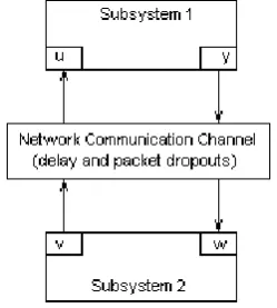
[image:1.595.365.490.522.661.2]A typical NCS can be thought as two subsystems interacting across a common communication network.
Figure 1. General framework for NCS
Subsystem 1 represents the plant, sensors, actuators and the quantizers. The system as seen by the controller side can have a discrete representation to match with a discrete controller. Subsystem 2 represents the controller.
Subsystem 1:
1 A B Cp, p, p
(1)
p p
p x t A x t B u ty t C x t t
R
(2)
where
Mu t R are the system input signals,
R y t Rare the outputs and x t
RN are the states of the system.p
A , Bp and Cp are plant matrices of compatible dimensions.
For simplicity the plant is assumed to be linear and time invariant.
Subsystem 2:
2 E F G Hc, c, c, c
(3)
c c
cc
z kh h E z kh F w khv kh G z kh H w kh
(4)
where w kh
RRare the discrete inputs, v kh
RM discrete outputs and
Qz kh R the controller states. Ec,
c
F , Gc and Hc are the discrete matrices of compatible dimensions.
h represents the sampling time of the sensors. It is assumed to be constant for all sensors to facilitate the implementation of the controllers.
1, 2,...,
i
h h i R
2.1. Network Induced Delay
The type of data transmitted across the bus architecture is countless number of small packets. In control applications the number of nodes that share the network can vary. The network can be dedicated for control purposes; or shared as in remote control applications over the Internet.
In any network, there is an effective transmission bandwidth. This bandwidth is defined as the maximum amount of meaningful data that can be transmitted per unit of time [14]. The utilization of this bandwidth depends on the packet size, the nodes requirements such as sampling rates and synchronized operations, and the MAC [14]. Not all network traffic is due to successful transmissions, collisions are usual among nodes attempting to transmit and the way the MAC deals with these collisions adds either a random or deterministic time-varying delay.
For control design, the delay has to be bounded. A practical assumption is to define this delay as a scalar nonnegative time-varying function of time for t ≥ 0 [28]. This is the network induced-delay k, k1, 2,... in NCS. In our solution only network delay is considered and is split into input delay and output delay.
Input delay CAk is the time to transmit data between the controller and the ith actuator. Assuming that the control signal is constant after the sample-and-hold device, i.e.
f t f kh , kh t
k1
h, the input delay is:
( ) CAk
u t v kh , (5)
The input delay is assumed to be bounded
(min) (max)
CA CAk CA
, and the minimum delay can represent the inherent transmission delay.
Output delay SC k is the time to transmit data between the ith sensor and the controller. Based on a constant sampling rate, the output delay in a sampling instant is:
( ) SC k
w kh y t , (6)
where SCminSC kSCmax is bounded.
2.2. Ethernet network delay
The total time delay
to transmit data from the source node to the destination node can be expressed as three components [14]:i. the time at the source node, ii. the time at the network channel and, iii. the time at the destination node.
At the source node, the delay time consists of computation time and waiting time. Waiting time is critical in network traffic and consists of the time a message waits queuing in the buffer Tqueue and the time a message waits once the node is
ready to transmitTblock.
At the network channel, the time delay is a combination of the transmission delay and the propagation delay. This delay depends on the message size, data rate and length of the network cable [14].
Once the data has reached the destination node, there is a delay due to decoding and computation processes. The delays ((min)) at the network channel and at the destination channel can be calculated based on the network specifications. However, the delay at the source node and more specifically the delay, due to the waiting time is difficult to analyse. This delay is responsible for the time varying nature of the network.
Waiting time is the time a message has to wait before it is sent across the network. It depends on collisions, contention and transmission mechanisms and varies from network to network. The queuing time is the most difficult to determine, as it depends on the blocking time and periodicity of the messages. The blocking time is protocol dependent [24] and represents the way protocols manage transmissions and collisions.
control-oriented protocols such as TOD (try-once-discard) [15] and other dynamic bandwidth allocation methods.
The way each node access the network can be random or prioritised. For Ethernet-based networks the node that wants to transmit listens to the network and transmits once the network is idle. In case of collision, the transmitting node stops transmitting and waits
x
units of time to retransmit. This random time is determined by a Binary Exponential Back-Off algorithm.After 16 attempts, the node stops transmitting and a report failure is sent. Hence the blocking time has a probabilistic behaviour [14] which can be described as follows:
16
1
j
k block k resid
j
E T E T T
(7)where, Tresid is residual time seen by the node until the network is idle.
2.3. Delay Distribution
Under heavy traffic load, the time-varying nature of the delay can hardly be deterministic even for CAN-based networks [14]. In the worse scenario, a stochastic model of the network traffic can be formulated as a probabilistic process with known distribution. This distribution associates the probability that a particular delay happens.
As stated by Ryu in [19], Ethernet-based networks on Internet applications present Poisson-like network traffic under heavy traffic loads. In Pahjola’s work [17] this distribution of the delay is considered as a Gamma distribution.
3. POLYTOPIC DESCRIPTION
For control design, both delays can be lump together as far as no packet dropouts are present. The resulting delay is still time-varying and random; however it can be introduced in the system model as input delay. The resulting model represents a rough approximation of network behaviour.
3.1. Time Delay Systems approximation
The input time delay modifies the state-space realization of the system as follows:
p p
p kx t A x t B u t
y t C x t t
R (9)
where ksc k, ca k, . ( ) M
u t R is the system inputs,
( ) R
y t R is the outputs and ( ) N
x t R is the states. Ap, Bp
and Cp are plant matrices of compatible dimensions.
It is possible to sample systems with delays when the control signal remains constant between sampling instants [2]. The resulting sampled-data system is finite dimensional, however due to the varying nature of the network delay, the sampled-data systems becomes time-varying.
The random nature of the delay makes the sampling process inaccurate. The randomness of the delay can be included by
least three different ways: a network induced-delay less than the sampling period, greater and multiple integer of the sampling period or simply greater than the sampling period. The last case involves the former two and can be assumed as the most general case.
The presence of network induced-delays greater than the sampling period is not very common. This case can be assumed to be similar to packet dropouts or unreliable communication with vacant sampling. Vacant sampling is defined as the absence of packets on the controller side during a sampling time. In this case, the controller uses the previous received packet or an interpolated value.
In our design the system with varying delays has a discrete realization based on time-driven sensors and event-driven actuators. For the maximum admissible delay, the discrete state-space realization of the sampled-data system is:
' 0 ' 1
1 ,
, 1
p p k k
p k k
x k E h x k F h u k
F h u k
(10)
where '
k kh k
, '
0kh, k0and integer;
The above sampled-data system is time varying in Fpi,
1, 2
i .
The resulting system represents a polytopic model subject to:
'1 , ,
i
d Ep h Fpi hk
(11)
and is the set,
' ' '
1 2
, , , , , ,..., , ,
cl pi cl pi cl pi k
CoE h E h E h E h E h E h
(12)
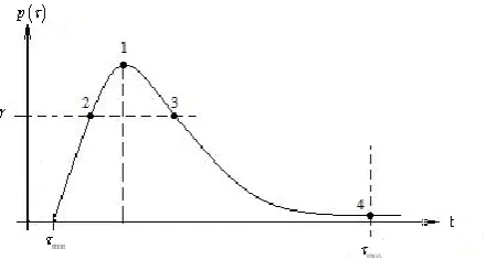
with i1, 2 , k1, 2,... and Co referring to the convex hull and defined by linear models. The number of linear models in the set is not finite because the values of
', pi k
[image:3.595.310.531.537.660.2]E h constitute an approximation of the sampled-data NCS for random delays.
Figure 2. Delay Dependent set of Models
is a sweeping factor in the pdf of the delay and represents a range of possible models with good performance for a given controller.
4. CONTROLLER DESIGN
Most of the literature in PID controllers for NCS is based on either parameter optimisation [9], [17] and [24]; or adaptive parameter adjustment [7], [12] and [13], to meet desired design specifications. Sufficient conditions for stability have to be derived from maximum allowable delays. In an optimal fashion, the controller design is jointly feasible if the closed loop system meets the design specifications [20]. From the literature of time delay systems, PID controllers have proved being stable when the parameters are subject to the delays [20].
For delay-dependent systems, the use of the derivative action is limited because linear extrapolation based on future values is not effective [1], but NCS is a particular case of systems with delays where control signals using prediction values can be suitable.
The controller to be implemented is a discrete PID controller of the form:
2
0
1 i , sp
i
v k v k C e k i e k y k y k
(13)where, ysp
k is the reference signal and admissible ranges of the controller parameters are: C00, C1 C0 and
C0 C1
C2 C0 . These ranges are aimed to ensure positive gain [11].
The controller parameters are sample rate-dependent. If the NCS model includes scheduling methods, the controller design leads to multi-rate digital controllers. In this paper, a single-rate controller design is sufficient to control the system.
4.1 Pseudo-Probabilistic Robust Approach
Assuming that the set of polytopes is known, i.e. i1 d
,
1, 2, 3
i , then two steps are necessary in the controller design. Firstly the convex optimisation problem must be solved for the model that represents the most probable delay
1 1
d
. If performance specifications are satisfied for this model, it can be stated that there exists a controller that satisfies all the set, otherwise less conservative specifications have to be considered.
The other models depend on the tuning parameter. By sweeping the pdf , a range of possible models bounded by
2 3
1,..., 1
d d
can be generated . Thus performance specifications can be formulated using the closed loop model of combining id1 i1, 2, 3with the optimal PID controller
2 op
.
Stability conditions can also be specified using the fourth system model. In this study a fourth model is used to include the worse case model 4
1
d
. If the closed loop system
represented by 4 1
d
and 2o is stable, then stability is ensured
for the full set.
The system is said to be stabilizable if and only if the following LMI is feasible, with P, Q and Q1 bigger than zero:
1 ' 0 ' 1 1 ' ' 0 1 0 0 0 0 0 0 0 T Tp i a
T
p i a
p i a p i a
P Q Q A K
Q F K
Q F K
A K F K F K P
(14)
5. NUMERICAL EXAMPLE
To illustrate the above design method the NCS is defined as a 10 node system connected across a communication network.
k
is the lumped delay and represents the round trip delay in Ethernet-based networks
Network parameters are taken from [14] to match with real values. The packet size is 8 bytes. Each node represents a simple first order system as follows:
*
* 0 1
.99 .0006 .0001
1 .0006 1 0 1
.0006 1
572 6
i i i i
x k x k B u k B u k
h e
The total time to send 10 messages over the networks is [14]: 576
s
. If the period is shorter than the total transmission time the traffic load increases and the network can become unstable. In the simulations, the sampling period will be equal to min
[image:4.595.299.560.511.578.2]
, thus the network induced-delay is zero or
k. The average time delay defined is 1267
s
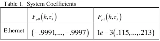
[14].Table 1. System Coefficients
'0 ,
p k
F h
'1 ,
p k
F h
[image:4.595.312.539.623.685.2]Ethernet
.9991,..., .9997
1
e
3 .115,...,.213
Assuming a tuning factor corresponds to 70% of the probability of the delay, the resulting set is as follows: Table 2. Controller Parameters0
C C1 C2
Average Delay .0074 .016 -.0105 Probability Delay .0027 .0054 -.0037
The controller design is based on constrained optimisation using pattern search in MATLAB. Restrictions were defined as inequalities. The design is highly dependent on the initial conditions. Convergence of the controller parameter search was obtained only when the Co was weighted ten times
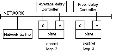
Simulations are based on a Simulink model using TrueTime1.5. This simulator allows co-simulation of controller-task execution in real-time kernels, network transmission and continuous plant dynamics [30]. Models 1 and 3 from Fig. 2 are tested. The three controllers are implemented as nodes in an Ethernet network with 10Mbps. The remaining 7 nodes are simulated as network traffic.
Figure 3. Control loops distribution
[image:5.595.64.270.329.499.2]The delays used to obtain the models are simulated by changing the probability of packet lost. The following results were obtained:
Figure 3. Output response for model 1
The simulations show better performance for average delay for model 1 where the correct delay is used. However, the performance of the proposed controller is better in model 3. For model 3, the controller based on Average delay tends to instability.
Figure 7. Output response for model 3
6. CONCLUSIONS AND FUTURE WORK
It was argued that to achieve good performance both network and system performance are to be considered. Furthermore, instability of the NCS is merely instability of the network due to heavy traffic. Network induced-delays have been lumped together for design purposes. The controller design is based on the expectation of the most probable delay accompanied by a set of models that depends on a tuning parameter
. The method used to tune the controller can be extended to a probabilistic robust approach where the set of models will depend on random sampling of the pdf. Hence the controller design is not limited to a reduced range of models.7. ACKNOLEDGEMENTS
This work has been supported by the Programme Alβan, The European Union Programme of High Level Scholarships for Latin America, scholarship No.E07D402078EC.
The author expresses gratitude to Dr. Leonardo Giovanini for his technical comments and suggestions.
References
[1] Åström, K., Häggliund, T.: “The future of PID control”, Control Engineering Practice 9, 2001.
[2] Åstrom K. J., Wittenmark B.: "Computer controlled systems, Theory and Design", 1990
[3] Bompart, V., Apkarian, P., Noll, D.: “Control design in time and frequency domain using nonsmooth techniques”, Systems and Control Letters 57, 2008.
[4] Dai, J., Cui, B.: “A new delay systems approach to quantized networked control systems”, Manuscript draft, Jiangnan University, 2008.
[5] Delchamps D. F.: "Stabilizing a Linear system with quantized state feedback", IEEE Transactions in Automatic Control, Vol. 35, No 8, August 1990.
[6] Boyd, S., Barratt, C.: “Linear Controller Design: Limits of Performance”, Prentice Hall, 1991.
[7] Fang, L., Wu, Z.: “Fuzzy immune self regulating PID control for Networked Control Systems”, IEEE, 2006.
[8] Giovanini, L., Marchetti, J.: “Shaping Time-Domain responses with Discrete Controllers”, Ind. Eng. Chem. Res., 1999. [9] Ghude, S.: "Design a PID Controller with Missing Packets in a
Networked Servo-System", Master dissertation, March, 2007. [10]Harle, D.: Communication Network notes, University of
Strathclyde, 2007.
[11]Isermann, R.: “Digital Control Systems”, Springer-Verlag, Berlin, 1981.
[12]Kyung, C., Suk, L.: “Remote Controller Design of Networked Control Systems using Genetic Algorithm”, IEEE, 2001. [13]Li, S., Wang, Z., Sun, Y.: “A novel Auto-tuning Robust PID
controller for Networked Control Systems”, IEEE, 2003. [14]Lian F., Moyne J., Tilbury D.: "Performance Evaluation
Control Networks: Ehternet, ControlNet and DeviceNet", Technical report UM-MEAN-99-02, Febrary 1999.
[15]Lian F., Moyne J., Tilbury D.: "Analysis and Modelling of Network Control Systems: MIMO case with multiple delays", Proceedings of American Control Conference, Arlington, Virginia, June 2001.
[16]Oppenheim A. V., R. Schafer W., Buck J.R.: "Discrete-Time Signal Processing", 1999.
[17]Pahjola Michael: "PID Controller Design for Networked Control Systems", Master’s thesis for the degree of Master of Science in Technology, Espoo, 9. January, 2006.
[image:5.595.66.269.594.754.2][19]Ryu, S., Cho, C.: “PI-PD-controller for robust and adaptive queue management for supporting TCP congestion control”, Proceedings of the 37th Annual Simulation Symposium, IEEE, 2004.
[20]Silva, G.: “PID controllers for Time-delay systems”, 2004 [21]Velasco, M., Marti, P., Villa, R., Fuertes, J.: “Stability of
Networked Control Systems with Bounded Sampling Rates and Time Delays”, IEEE, 2005.
[22]Velasco, M., Marti, P., Frigola, M.: “Bandwidth management for distributed control of highly articulated robots”, IEEE International Conference on Robotics and Automation, Barcelona, Spain, April, 2005.
[23]Yang T. C.: "Networked Control Systems: a brief survey", IEE proceedings in Control Theory and Application, Vol. 153, July 2006.
[24]Zhang, W., Branicky, M., Phillips, S.: “Stability of Networked Control Systems”, IEEE Control Systems Magazine, February 2001.
[25]Walsh G. C., H. Ye, Bushnell L. G.: "Stability analysis of networked control systems", IEEE Trans. Control Syst. Technol., pp. 438-446, 2002.
[26]Kharitonov, V., Gu, K., Chen, J.: “Stability of Time-Delay Systems”, 2003.
[27]Low,S., Paganini, F., Doyle, J.: “Internet congestion control”, IEEE Control systems Magazine, February 2002.
[28]Halevi Y., Ray A: "Integrated communication and control systems, Part I-Analysis", Journal of Dynamic Systems, Measurements and Control, Vol. 110, pp. 367-373, December 1988.
[29]Richard, J.: “Time-delay Systems: an overview of some recent advances and open problems”, Automatica, Vol. 39, April 2003.