BUCKLING OF AXIALLY COMPRESSED CYLINDRICAL SHELLS
WITH LOCAL IMPERFECTIONS
,,o. r
(',.. by
�'t-
!).S.Krishnakumar
B.Tech.,M.S.,M.I.E.Aust.,
submitted in fulfillment of the requirements
for the degree of
Doctor of Philosophy
in the
Department of Civil and Mechanical Engineering
UNIVERSITY OF TASMANIA
Australia
diploma in any University, and that, to the best of my knowledge and
belief, this thesis does not contain any copy or paraphrase of
material previously written or published by any other person, except
when due reference is made in the text of the thesis.
.
..
CONTENTS
Abstract
Acknowledgements
III
Introduction 1
Buckling of Cylindrical Shells in Axial
Compression - Historical Background 7
Space Frame Theory 25
Finite Deflection Analysis of Simply Supported
Isosceles Triangular Plates 54
Modifications to the Space Frame Theory 99 Geometric Considerations of the Buckled
Cylindrical Shell 129
Experimental Set Up 160
Tests on Shells Before Introducing Defects 185
Tests with Imposed Defects 237
Conclusion 300
309 Ultimate Strength of Isosceles Triangular Panels 318 Moire Method for the Determination of Radial
Deformations in Cylindrical Shells 326
Appendix C. Test Data 356
Publications 367
Chapter 1. Chapter 2.
Chapter 3. Chapter 4.
Chapter 5. Chapter 6.
Thin cylindrical shells in axial compression are known to be highly sensitive to geometric imperfections. Previous theoretical and experimental investigations have mostly concentrated on imperfections of small amplitude extending over the whole surface or at least over the whole circumference of the cylinder. Local imperfections occurring naturally are often found to be similar in form to the diamond-shaped facets of the buckle pattern of the collapsed cylinder. The current study is aimed at investigating experimentally the effect of such facet-shaped dimples on the load bearing capacity of the axially
loaded circular cylindrical shell and evaluating the applicability of the space frame theory in predicting the same.
system, based on the grid reflection technique, to monitor the growth of initial imperfections and the imposed defects during loading. Over thirty high quality spun-cast epoxy shells were tested before and after imposing the defects. The preliminary tests conducted assess the validity of the space frame theory in predicting the secondary collapse loads and that of the geometric criteria developed for the post-buckling mode. The experiments with imposed defects investigate the effect of changes in the defect size on the collapse load, and the influence of additional defects imposed on the shell. In addition to evaluating the applicability of the space frame theory, the test results are used to develop empirical formulae for estimating the effect of facet-shaped local defects on the collapse of axially loaded circular cylindrical shells.
The author is greatly indebted to Dr.C.G.Foster for introducing him to the fascinating field of Shell Stability and for the constant encouragement, guidance and support he provided during every stage of this study. The fruits that are gathered herein are blossoms of the seeds sown and nurtured by Foster.
The author is also grateful to the many others without whose assistance this work could not have been completed. In particular he wishes to thank
: Mr.Basil Stiberc and the other staff members of the Engineering workshop for the manufacture of the testing apparatus and for their patient and prompt assistance in preparing the end-rings for the testing of each shell,
: Mr.Peter Jordan for preparing the drawings for the loading frame, : all the other academic as well as non-academic staff members of
the Engineering faculty for their encouragement and support,
: Mr.Pichit Rerkshanandana, discussions with whom led to the germination of many of the ideas presented herein,
: and the University of Tasmania for the financial assistance provided.
INTRODUCTION
The present study was undertaken with the objective of investigating the effect of local defects on the buckling of axially compressed circular cylindrical shells, with the aid of the Space Frame Theory.
The effect of initial imperfections on the axial load carrying capacity of cylindrical shells has been the subject of a large number of investigations in the last four decades. Beginning with the earliest studies, in which imperfections of the same shape as the buckling modes of the cylinder were considered, a variety of imperfection shapes have been investigated, both theoretically and experimentally. These studies have conclusively shown that the stability of the cylindrical shell is extremely sensitive to very small imperfections extending over the whole surface or at least over the whole circumference of the cylindrical shell. While the emphasis has been on imperfections of small amplitude spanning over a large area, imperfections of large amplitude spanning over a small area have mostly been neglected. Thus, in spite of the large body of literature that has been produced on the effect of imperfections, if one were to ask "what is the effect of a single large dimple on the shell wall ?", the answer is not readily available. To be fair, it must be admitted that quite a substantial amount of information is available on the effect of circular and non-circular cut-outs. However other than
cut-outs, local defects, particularly of the nature of dimples or indentations on the shell wall, have received very little attention.
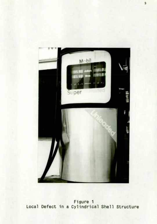
Imperfections in the form of local geometric deviations of the shell wall may easily be caused during the manufacturing stage, or in the course of handling and erection, or even under service conditions of the shell structure. Such imperfections are generally large, in the sense that the maximum deviation of the shell wall from the true cylindrical shape can be many times the thickness of the shell (even though they might cover only a small area of the surface of the cylinder), and thus do not come under the category of the small general imperfections which have formed the subject of most of the theoretical investigations conducted so far. Further, local defects when present on a shell, are usually present in addition to the general imperfections, which are more or less unavoidable. It is obviously of practical interest to investigate the detrimental effect of such local defects on the load bearing capacity of cylindrical shell structures.
Figure 1
"naturally" occurring defect shape, that the author happened to notice in passing. It is interesting that the shell usually prefers to develop two nodes, at either end of the central (tangential) fold,
rather than one, when it is subjected to a lateral impact. The reason for this preference is probably the same as that which motivates the axially compressed shell to assume the Yoshimura pattern, that is, the deformed surface in either case becomes a near developable surface. It may be observed that in both cases the diagonal members are not actually straight, hence the deformed pattern is not exactly diamond-shaped; but for practical purposes, it may be approximated by the diamond-shaped facet of the Yoshimura pattern.
Since there is not much empirical data available on the effect of local defects, the main objective of the proposed study has been to obtain experimental data by conducting a series of tests on shells of different dimensions with imposed defects of different sizes. This experimental data is used to assess the validity of the space frame theory in predicting the axial load bearing capacity of cylindrical shells with local defects. Buckling and post-buckling tests were also conducted on the shells before imposing the defects. The former was done to assess the extend of load reduction caused by factors other than the imposed defect, with a view to isolating, if possible, the detrimental effect of the imposed local defects. The post-buckling tests were conducted to obtain experimental data on secondary collapses, which was used to assess the basic theory of the space frame model.
The first three chapters in the thesis, including this one, are introductory. In chapter two a survey of the developments in research on the buckling behaviour of axially loaded cylindrical shells is presented, providing the necessary background for the current work. Chapter three gives a brief description of the space frame theory as it was originally proposed by Foster.
The next three chapters deal with the theoretical Investigations. In chapter four a large deflection analysis of simply supported isosceles triangular plates is conducted in an attempt to establish the effective width of the sides of the triangular facets of the space frame. While this attempt was unsuccessful, another approach was used to establish the effective width, which is presented in chapter five, along with the resulting modifications to the space frame theory. The geometrical aspects of the buckled configuration of the axially loaded cylindrical shell are investigated in chapter six.
The experimental work is presented in chapters seven, eight and nine. In chapter seven, the experimental set-up, loading frame and the optical system used to monitor the growth of initial imperfections as well as the imposed defects are described. Chapter eight presents the experiments conducted on shells without any imposed local defect. The results of the tests with imposed defects are presented in chapter nine. Based on these results, empirical relations are developed for predicting the effect of local defects.
CHAPTER 2
BUCKLING OF CYLINDRICAL SHELLS IN AXIAL COMPRESSION - HISTORICAL BACKGROUND
The Classical buckling load for an isotropic circular cylindrical shell in axial compression is given by
2 r E t2 Pcl =
1
3 (1-v 2 )(2.1)
where E is the Young's Modulus, v the Poisson's ratio, and t the thickness of the shell. This solution was obtained before the First World War by Lorenz, Timoshenko and Southwell l . The classical load, however, is seldom realized in actual test conditions. In experiments conducted during the first half of the century, test results ranged between 15 and 60% of this theoretical value. The first attempt to explain the discrepancy between theory and experiment was made in 1934 by Donne11 2 who introduced a set of simplified non-linear equations for the large deflection analysis of cylindrical shells.
the basis of most of the theoretical investigations on the buckling and 'post-buckling of cylindrical shells. A more complete set of non-linear equations were developed around the same time by Flagge3, without resorting to the shallow shell approximations. Fliigge's theory
is often employed to check the accuracy of Donnell's equations, or in situations where the latter is not applicable.
Donnell's classic paper2 was followed by a series of theoretical and experimental investigations, which, spread over the next four decades, have led to a more complete understanding of the phenomenon of shell buckling and the special role played by initial imperfections in it. The major developments in bridging the gap between theory and experiment are summarized in the following sections.
2.1 Effect of Edge Restraints and Prebuckling Deformations
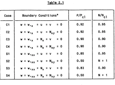
The classical theory ignores boundary conditions and approximates the prebuckling state with a membrane solution. Several researchers4-1I investigated the effect of boundary conditions and the prebuckling bending deformations caused by edge restraints, by numerical as well as analytical methods. The final outcome of these investigations (when both effects are included) are summarized in Table 2.1. The first four cases (C1 to C4) correspond to clamped edge conditions, while the last four (Si to S4) refer to simply supported end conditions. (The data presented in this table is from ref.11, and
Table 2.1
Case Boundary Conditions*
P/P
c1N/Ncl
Cl w = w,x = u = v = 0 0.92 0.95 C2 w = w,x = u = Nxy = 0 0.92 0.95 C3 w = w,x = Nx = v = 0 0.90 0.90 C4 w = w,x = Nx = Nxy = 0 0.90 0.90 Si w = w,xx = u = v = ° 0.85 0.95 S2 w = w,xx = u = Nxy : ° 0.50 N = 1 S3 w = W,xx 7' Nx = v =0 0.83 0.90 S4 w = w,xx = Nx = Nxy = ° 0.50 N = 1
The constant values given in Table 2.1, of course, pertain only to thin shells of medium length. Thick short shells, which buckle in the axisymmetric mode, have higher buckling loads, and very long shells fail by Euler buckling at lower loads. The effect of elastic edge restraints was also investigatedI2, and it was shown that very little elastic restraint is sufficient to obtain buckling loads close to the values quoted above. Although the critical load is obtained as half that of the classical load in two cases of simple support (S2 and S4), the condition that the edges of the shell be free to move in the tangential direction is seldom realized in practice. Hence in actual test conditions, the effects of edge restraint and prebuckling deformations account for only 10 to 15% reduction in the theoretical
load, still leaving a large gap between theory and experiment.
2.2 Large Deflection Analysis
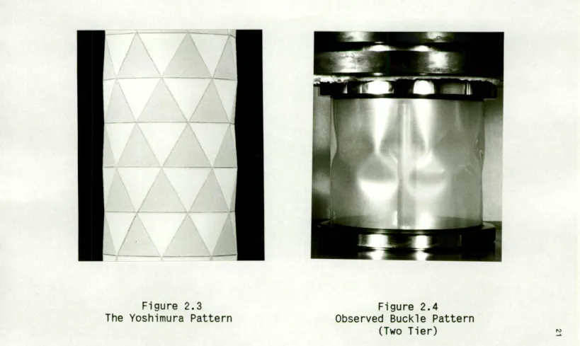
2.3 The Yoshimura Pattern
2.4 Experiments on Near Perfect Shells
Meanwhile considerable advances were made in experimental techniques. With sophisticated testing equipment it was possible to subject the shell to uniform loading conditions without the problems of misalignment and eccentricity. Improved methods of fixing the shell to the end plates ensured almost complete circularity of the ends of the shell. At the same time using advanced manufacturing techniques like electroplating 20,21 and spincasting 22-24, shells with almost perfect cylindrical shape and minimum variations in thickness (of the order of 2 to 5%) could be made. Tests conducted on these near perfect shells have yielded buckling loads within 10 to 20% of the classical load, i.e., in close agreement with the reduced theoretical value taking into account the edge restraints and prebuckling bending deformations. While these experiments proved that the theory is indeed valid for perfect cylindrical shells, they also showed that initial Imperfections are the main culprits in reducing the buckling load in normal test conditions. It became clear that external disturbances present during usual test conditions are hardly of any consequence to warrant scrutiny; although some experimenters25-27 have shown that by deliberately imposing such disturbances (like applying lateral forces on the shell), the shell can be made to buckle prematurely.
2.5 Effect of Initial Imperfections
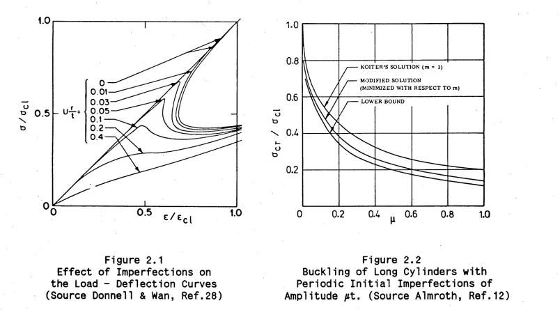
the subject of many investigations in the past several decades. The first successful attempt in this regard, using the non-linear approach, was that of Donnell and Wan28. Improving upon Donnell's earlier work2 , they considered an initial deviation of the same shape as the assumed normal deflection of the shell, and showed that with increasing amplitude of the initial deviations the peak of the load deflection curve dropped drastically (see Figure 2.1, taken from ref.28). Expressing the amplitude of initial deviation in terms of a constant "Unevenness parameter" U, and the square of the radius to thickness ratio, they showed that a small value of 0.00015 for the constant U was sufficient to explain most of the discrepancy observed between theory and experiment.
The quantitative results of Donnell and Wan are only approximate in nature, and are seldom used for design purposes. Also
0
0
.2
0
.4
0
.6
0
.8
1
.0
0
.8
0
.6
0
.4
02
KOITER'S SOLUTION (m = 1) MODIFIED SOLUTION
[image:21.827.17.821.51.496.2](MINIMIZED WITH RESPECT TO in) LOWER BOUND
Figure 2.1
Figure 2.2
Effect of Imperfections on
Buckling of Long Cylinders with
the Load - Deflection Curves
Periodic Initial Imperfections of
equations of Donnell for simply supported shells of finite length, showed that effect of imperfections in the shape of the buckling mode is nearly the same as that obtained for the infinitely long shell. The effect of prismatic imperfections in the shape of flat spots extending over the full length of the cylinder was investigated by Bhatia and Babcock".
A large number of theoretical investigations on the effect of initial imperfections are based on the asymptotic theory of initial post-buckling behaviour developed by Koiter33'34. Classifying the bifurcation point into three types, asymmetric, stable symmetric and unstable symmetric, Koiter showed that the imperfection sensitivity of a structure depends on the type of bifurcation point associated with it. In particular, for the cylindrical shell in axial compression, he showed that small imperfections in the shape of the classical axisymmetric buckling mode can significantly reduce the buckling load and obtained an asymptotic solution for small but finite values of the imperfection amplitude. Almroth12 modified Koiter's approximate analysis by including the effect of boundary conditions and non-linear prebuckling deformations and assuming a more general buckling pattern, to obtain results which predicted slightly lower buckling loads. Figure 2.2 showing the results of Koiter and Almroth is from ref.12.
imperfections. Extending Koiter's theory to cover axisymmetric imperfections of different wavelengths they obtained results which were in close agreement with the observed buckling loads. These studies indicated that the minimum buckling load is obtained when the wavelength of the axisymmetric imperfection is equal to that of the classical axisymmetric buckling mode. The effects of random and localized axisymmetric imperfections were also investigated39-33. Theoretical investigations on the effect of random axisymmetric
imperfections were conducted by Amazigo39 and Van Slooten et al 49, using a probabilistic approach. Using the same approach, Hansen41,42 has extended Koiter's asymptotic theory to the case of general random imperfections. Hansen's studies have indicated that non-axisymmetric and general random imperfections can have a greater degrading effect than axisymmetric imperfections, on the buckling of axially loaded cylindrical shells.
The effect of actual imperfections present on shells was first investigated by Arbocz and Babcock43. By carrying out surveys of
While a variety of imperfection shapes have thus been investigated, a notable omission in this regard is that of specific local deformations. It may also be pointed out that while the theoretical studies using the asymptotic approach is strictly restricted to small initial deviations, the applicability of the non-linear approach using Donnell's equations for local deformations of large amplitude is also doubtful, owing to the shallow shell approximations involved.
The effect of diamond-shaped local dents (of the type considered in this study) on the ultimate strength of thick tubular members have been previously investigated48-50. However failure in these tubes is caused by yielding, and bears no resemblance to the elastic buckling of thin cylindrical shells.
2.6 Buckling and Post-buckling Modes
According to classical theory, the buckling mode for the non-axisymmetric case is not uniquely defined. The minimum value of the buckling load is obtained by using the condition l
N2 + q2 - q q
o = 0 (2.2)
where N is the number of circumferential waves, q is the axial wavenumber*; and qo is the critical wave number for axisymmetric buckling given by
= [ 12 (1 - v2) R2/ t
2 ]1/4 q
o (2.3)
Thus any combination of N and q which satisfies equation (2.2) is admissible. However, on assuming a square wave formation, i.e., that the wavelengths in the axial and circumferential directions are equal, which gives N = q, eqn.2.2 yields the "classical" value of N ast
Ncl = [-4 3 (1 - v2) R 2 li/4 (2.4)
Non-linear theory, considering the effects of edge restraints and prebuckling deformations, predicts critical values for N which are only 5 to 10% smaller than the above value (see Table 2.1).
The actual number of circumferential lobes observed after the shell has buckled, however, is much smaller than that predicted by
* The axial wavenumber q = mrR/L, where m is the number of half-waves in the axial direction, R and L the radius and length of the shell. t The same result may also be derived by putting dN/dq = 0 in eqn.2.2
theory, though the buckles are more or less square. (This discrepancy was also first pointed out by Donne112). While the discrepancy in the buckling loads has been successfully attributed to the presence of initial deviations, imperfections cannot account for the reduction in N, since the latter is observed even in near perfect shells.
Several investigators22,23,25/52-54 have attempted to determine the initial buckling modes by using high speed photography to record the growth of the deflection pattern during the process of buckling. These studies have shown that in the initial post-buckling stage, the number of circumferential lobes is much higher (close to the value predicted by theory) than that observed at the final stage. On the basis of comparisons between the 45° isoclinics observed on shells made of photo-elastic plastic and those predicted by theory, Tennyson 54 has reported the observation of the classical mode at the inception of buckling. He further states that this initial mode rapidly degenerates into the diamond buckling pattern, and that in the final stage (which is reached within a few milli-seconds) the observed isoclinics bear no resemblance to those predicted, indicating that the theory is valid only in the initial post-buckling stages.
Esslinger and Geier 25 have suggested that in the final stage the shell assumes the mode corresponding to the "characteristic curve"; the "characteristic curve" being defined as that curve in the theoretical post-buckling diagram (plotted for different values of N), which gives the minimum possible end-shortening for the shell under consideration. Although it has not been clarified as to why the shell should choose to stop at this particular curve; experimental evidence ll ' 25 indicates that the number of circumferential lobes actually present in the stable buckled state of the cylinder is much closer to the N corresponding to the characteristic curve than it is to the classical value of N.
De Neufville and Connors 55 as well as Hoff" have observed that the post-buckled N depends not only on the radius to thickness ratio but also on the length to radius ratio, and have hence developed empirical formulae relating N to both these quantities. (These relations will be examined in greater detail in Chapter 6).
He further observes that long thin shells with values of the Batdorf parameter* Z greater than or equal to 200 buckled naturally into the two tier pattern, although in the advanced post-buckling stages even the one tier pattern could be realized in these shells by adjusting the deformed shell wall appropriately with the fingertips; whereas in shells with values of Z less than or equal to 100 only the one tier pattern could be realized.
2.7 Secondary Buckling
Many researchers"'"'" ," have experimentally investigated the behaviour of the cylindrical shell after it has buckled under axial compression. In these controlled end-shortening experiments, it has been found that on subjecting the shell to further end-shortening after it has buckled, the load gradually rises, until at some specific value of the load, the shell suddenly undergoes a second collapse, snapping through into a new mode which has one circumferential lobe less than the previous configuration. This second mode is also a stable one, so that further end-shortening again raises the load and results in yet another collapse in which the circumferential number of lobes is further reduced by one. The post-buckling behaviour of the axially compressed cylindrical shell is thus characterized by a series of secondary collapses, each one producing a successive reduction in the value of N (see Figure 2.5).
0
2
3
1.0
0.8
Shell S2
t =0.148 mm
R=77.1 mm
L=167 mm
0.6
■•••.0
at'
)
0.4
,Figure 2.5
Yamaki (Ref.11, page 223) has reported that only in shells which have buckled into the two tier pattern, the secondary buckling produces a reduction in N; the secondary collapse of shells which have buckled into the single tier pattern results in the formation of additional buckles initiating local torsional deformations. It may also be mentioned that with deflection functions representing the one and two tier patterns, using Donnell's non-linear equations, Yamaki obtained analytical post-buckling curves which were in reasonable agreement with the experimental ones for corresponding values of N. However, his analysis did not include an examination of the stability limits of these curves, hence the critical loads for the secondary collapses were not predicted.
CHAPTER 3
SPACE FRAME THEORY
The space frame model is based on the geometry of the Yoshimura pattern. The theory was developed by Foster 24/5862 - on the basis of numerous studies conducted on paper models, and proposes what is essentially a new interpretation of the buckling behaviour of cylindrical shells, drawing on the similarities between the "concave polyhedron" (Yoshimura pattern) and the buckled cylindrical shell.
Paper models reveal several important aspects concerning the Yoshimura pattern. Firstly, that a thin rectangular sheet of paper can be folded into such a shape is itself proof of the fact that the Yoshimura form is a completely developable surface. Secondly, although the folds of the paper cannot support any transverse moment - so that the folds as well as the corners of the model are in effect hinged or pin-ended - it is seen that the model can support a substantial amount of axial load. Thirdly, since the plane sheets of paper forming the interior of the facets cannot carry much stress, owing to their flexibility, it can be deduced that the end load is mainly supported by internal stresses along the folds of the model. The concentration of the stresses to this region can be attributed to the local increase in effective stiffness along the folds of the Yoshimura model.
held vertically bends over itself, it can easily be made to stand upright and even support some weight on top by folding it laterally to form an angle (see Figure 3.1). The unfolded sheet buckles under its own weight because its stiffness is very small, being proportional to the cube of the sheet thickness. The bending stiffness of the folded sheet is considerably greater, owing to the redistribution of mass about the centroidal axis, as indicated by the term W3 in the expression for the minimum moment of inertia of the thin angle section (see equation 3.11, page 42). It may however be observed that the greater section of each flange towards the free end of the folded paper tends to buckle under the load, and is thus ineffective, so that the weight is mainly supported by the two narrow strips of sheet immediately adjacent to the fold.
lbw Wig erg. rily ids* INK
amovo
gbat modh IO W° , •••-• At. 4 forma mesele/ism
.111: , y e- a•eld milhoma es low. OPP
gibs
owls mr.ed alp
ihe la as et fir dr am =I pilly to slows 1101 yak lir mut via
10 10 gig Iht puma 4..serlisliP Ilhe
ars111... lai mis boo ne w Me w. =ft. si mass
sembsimj baseS pie Mr. as be mit Tkr ma *Aid aslin= Ihe fel tbst mewl helm. da m is OE rairoal tory aholbissippladriorn met
s wAhriri. -is Jodi I. theespemerri wind ban % tie Meek! • ur o wl illimse kris the
•appierss dile b s
8timea m mo hr sbre mi 641.1114 bite isupi mid Irak
bog pg 1:- 1.11
• re wsposk w wow itswissa.aim amlimed sag p.m soll be inehri •a. w. Mr pod fro m d vow' 11•••=i foil= dm* bra
• eumirmi d in sem ea le Awl at g pit lid sis• •
4
thes es rim Ilk Gs iliaC
e
l
c
o
STANDARD500C STAPLES 26,6woo hrrea.0101 st • 1111
infigia* rap
Figure 3.1
approximate analysis of the post-buckling characteristics of the axially compressed cylindrical shell. However he himself did not persue this suggestion, probably because the secondary buckling characteristics of cylindrical shells were not widely known at that time. It was Foster, who, arriving independently at the same conclusion, realized the potential of the analogy and developed the space frame theory to provide a physical interpretation as well as a mathematical model for the secondary collapse phenomenon.
3.1 Physical Model for Secondary Collapse
A compressive end load on the space frame model produces compression in its diagonal members and tension in the tangential members. Hence the failure of the model takes place due to the buckling of the diagonal members of the frame. It is therefore proposed that the secondary collapse of the buckled cylinder is caused by the buckling of diagonal folds of the Yoshimura pattern. Using a number of paper models for illustration, Foster58'59 has convincingly described how such a collapse of the diagonal fold can lead to the reduction in the number of circumferential lobes of the buckled cylinder. The argument basically is as follows:
Figure
3.3
and FCG comprising the quadrilateral FHBG are replaced by two new triangular facets, namely FBH and FBG. The members HF and HB now carry compression while the new member FB is in tension. Thus a new pattern
is formed in which the facets are not isosceles triangles, since the side HF is twice as long as the side HB. For the same reason, the larger member HF is likely to collapse, hence this pattern is quite unstable and is only an intermediate stage. When the member HF collapses, a new tension member EB is formed, which is tangential and has twice the length of AB. Owing to the straightening of the member EB, the three triangles below it, namely ABC, AFC and AFE, as well at the triangle CFG, will now together constitute a new larger triangular panel, namely EGB; while a similar large facet will be formed on top of EB. Thus in the final stage of collapse, a new Yoshimura pattern is formed with facets twice as long and twice as wide as the facets in the original configuration. Assuming that this occurs all round the circumference, the number of circumferential lobes in the second pattern will be half that of the first pattern. If the Yoshimura model had, say, 32 facets around the circumference to begin with, each successive collapse will reduce this number by half, to 16, 8 and so on, until for N = 2, the model becomes completely flat.
nodes are fixed in space. Hence the formation of the tension member FB is immediately followed by another collapse (of the member HF) resulting in the reduction of N by a factor of 2. Whereas, in a cylindrical shell which has collapsed elastically, the nodes of the facets are not fixed, and the buckles are free to move around. Hence when the member FB is formed due the collapse of the first diagonal member (see Figure 3.4), the tension in this member will pull the facets on either side together, which expand and move in to take up the position of the collapsed facet. At the same time all other facets around the circumference also expand slightly, thus the final pattern has slightly larger buckles, and only one circumferential number less than the previous pattern.
Figure 3.4
placed along the axis of the shell. (The optical system used to take
these photographs is described in detail in Chapter 7.) The dark images in the middle are the facets of the two tier buckle pattern, the inner row being the top tier and the outer one the bottom tier. The photograph on the left was actually meant to record the first collapse mode which had thirteen lobes around the circumference. However, during the exposure (which takes about 8 seconds), the shell suddenly snapped through into the second mode (with twelve lobes); both these images
got
superposed on the same film. After this shot, another photograph of the second mode was taken, which is shown to the right, for comparison. It can be seen from the first photo, that the collapse occurred in a facet at about the twelve o'clock position. The movement of the adjacent buckles towards this position is clearly visible. The slight expansion of the neighbouring facets is also visible in the photograph. The buckles towards the bottom of the photograph seem more or less unaffected by the whole process. It may be mentioned that a similar superposed image, showing the lateral movement of the adjacent facets to occupy the position of the collapsed facet, was also obtained (again accidentally) in a test on another shell, S8, when it collapsed from a secondary mode of N = 10 to N = 9 while being photographed.3.2 Basic Relations
Noting that the buckled shape is an inextensional form, for
a cylinder of radius R, the length LI of the tangential members is
given by
Li = 27R/N (3.1)
where N is the circumferential number of facets*. Denoting the height
of the facets by L2 (see Figure 3.2), the aspect ratio of the facet is
defined as
A =
L2 / Li (3.2)The length of the diagonal member Ld = [A' + -4
0 11/2
From the geometry of the space frame (Figure 3.3), the angle 0 between
the facets adjacent to the diagonal member can be established as
(3.3)
(3.4)
where the angle subtended by the facet at the axis p = 27/N.
The inclination of the facets to the vertical plane may be obtained as
7 =
tan(,/4)]For a given end load P acting on the space frame, by considering the
axial equilibrium at the nodes, the force PI in the diagonal members
can be shown to be
P r 4A2 + 1 1/2 (3.6)
2 N
4A2 - tan2(p/4)iFrom radial
obtained as
equilibrium, the force P2 in the tangential members is
P2 = - PI + 1] 1 /2 (3.7)
[1 + cos(p/2)][A2
It may be pointed out that in this and the following discussion,
the compressive force is taken to be positive, so that the negative
sign in eqn.3.7 indicates tension in the tangential member. Since
secondary collapse has been shown to be caused by the buckling of the
diagonal member, the end load P at which secondary collapse occurs can
be obtained from eqn.3.6, if the critical value of PI at which the
diagonal member buckles can be established. However, at this stage
some additional elements are introduced, so that the model considered
by Foster for the buckling of the diagonal member is not that of a
simple Euler column. This model is described below.
3.3 Model for collapse of Diagonal Member
In section 3.1, it was shown that the collapse of the member
AC results in the formation of a new member FB. Although in the final
stage this member is in tension, at the beginning of the collapse, the
two halves of FB are in compression. Hence initially, the deflection
members. To account for this, Foster introduced springs on either side of the diagonal member"'", as shown in Figure 3.6. While these springs greatly enhance the buckling strength of the column, they also ensure that the buckling takes place only inwards, as it does in the Yoshimura model. To estimate the force in the springs, the strain in the member FN caused by the deflection MN at the midsection of the member AC is determined from the geometry of Figure 3.6. The strain due to the change in the geometry of the facet caused by loading is also taken into account.
From the geometrical relations evident in Figure 3.6, the altered length of the spring can be shown to be
1[ 2
FM = AF + 2.AB2 - 8.AB.MN .sin(p/4)] 1/2
]1/2 ( 31i 1 ) 2 while the original length is given by FN = [ L2 2 4.
The lengths AF and AB are respectively given by
AF = Ld41 Pi
2.E.W.t and AB = L141 P2 ] 2.E.W.t
DEFORMED POSITION OF AC
_
Figure 3.6
40
[ 8.L1.E.W.t.sin(p/4) P3 = MN.
L22 + 9LI2/4
1
(1 + cos(p/2)).Ld + Pi.
L22 + RI2/4
The angle
q
between the restraining force and the column is given by3L12/4 - L22
cos Tj = (3.9)
R
1/2 Ld.[L22 + I2/4]
3.4 Solution for the Buckling Load
Having determined the forces in the springs, the buckling of the diagonal member can now be treated as that of a pin-ended column,
loaded at the corners and restrained by transverse forces in the middle as shown in Figure 3.7. The governing differential equation is obtained as
El d2Y = - PI y + cos(0/2)] + P3 Sins') Cc:n(0/2) [ —2 Ld - – X] dX 2
whose solution is given by
y = CI sin(Jx) + C2 cos(Jx) - ; cos (0/2)
(3.8)
P3 sinn cos(9/ 2)
Figure 3.7
Ld
(1 +
cos(p/2)).LdL22 + 9LI2/4
1
.sinv.cos(0/2).[Ld/2 - u tan(JLd/2)] where J = PI/El ; the moment of inertia I being taken approximately
as
I = 1 6 W3.t.cos2(0/2) (3.11)
Using the boundary conditions y = 0 at x = Ld/2 and dx = 0 at x = 0,
the constants CI and C2 may be obtained as
P3 sinv cos(0/2) 1W cos(0/2)
CI = PI•J. ; 1,2 =•2 cos(JLd/2)
CI
tan(JLd/2)The deflection at the centre of the column is given by
P3
Ld
MN = C2 - cos (0/2) -= PI sinv cos(0/24—
(3.12)
(3.13)
Substituting for Pg from eqn.3.8 and for C2 from eqn.3.12 in eqn.3.13,
we finally obtain
8.L1.E.W.t.sin(p/4)
MN.[ 1 .sinv.cos(0/2).[Ld/2 - tan(JLd/2)] PI.[L22 + 9L12/4]
1
+ .cos(0/2).[ cos(Ad/2) 1] (3.14)
When the deflections grow very large, the term in the parentheses
on the left hand side of eqn.3.14 vanishes, hence the critical load is
8.1.1.E.W.t.sin(p/4)
1 .sing.cos(0/2).[Ld/2 - 1 tan(JLd/2)]
r
2 2 1 Pi. iL2 + BL1 /4j= 0 (3.15)
By substituting for cos(0/2) and sing from eqns.(3.4) and (3.9), the above equation may be rewritten as
pi.(A2 9/4)3/2 _ 16EWt
sin2(p/4)[Ld/2 - 1 tan(ad/2)] = 0 (3.16) LI
It may be pointed out that eqns.3.15 and 3.16 are identical to the ones used in ref.58, except for a change in sign in the second terms on the left hand side, which is due to the fact that in the original work tensile forces were considered positive whereas in the current work the compressive force is taken as positive.
3.5 Determination of Aspect Ratio and Effective Width
Matching the theoretical buckling load with one of these values Foster determined the effective width as 21 times the thickness of the shell. The secondary buckling loads obtained from the solution of eqn.3.16 using
A =
0.7 and Wit = 21 for the corresponding values of N are shown in the third column of the table. It can be seen that the agreement between theory and experiment is very good.Two further modifications were subsequently introduced by Foster. The first was the determination of the aspect ratio on an empirical basis58. For this purpose several Melinex cylinders were buckled under axial compression and measurements of the buckle dimensions were taken. The measured values of aspect ratio are shown in Figure 3.8a (from ref.58). Although the values show some variation with the circumferential number of buckles, this was attributed to the scatter of the results and a least square fit was obtained for the variation of the aspect ratio with the radius to thickness ratio as shown in Figure 3.8b. On this basis the empirical relation for the aspect ratio was established as
A =
1.606 - 0.121 ln(R/t) (3.17)Table 3.1
Comparison of Secondary Buckling Loads Predicted by Space Frame Theory with Esslinger and Geier's experimental data.
N *p
exp. lp th. 2p th. 3p th. 4p th.
15 275 271 275 308 280
14 260 254 257 284 258
13 235 236 239 261 237
12 215 218 221 238 216
11 200 200 203 216 195
10 185 181 184 194 175
Shell Data : R = 100 mm, t = 0.19 mm , E = 5.5 Gpa, v = 0.35 P
exp(primary) = 520 N' Pcl = 769 N, Pexp/Pcl = 0.68
* Experimental secondary buckling loads observed by Esslinger and Geier (quoted from Ref.58 - wherein they were obtained by reading from a graph in Ref.25)
I Using W/t = 21,
A =
0.7, and approximate M.I. (eqn.3.11)2 Using W/t = 23.5,
A =
0.85 (eqn.3.17) and approx. M.I.3 Using W/t = 23.5,
A =
0.85, and exact M.I. (eqn.3.18)(a)
-
1•0
cr 0.8
a_ In 0.7- 0-5
•
•
•
+a 0 o w•
44•V
IS 0 0•
0e xszt)
K •
• Ritr 1400 •R/T 445 Ft/r. 890 4R/T 234 R/ar 700 . R, 5 150
•
*5II
(b)
1•1150 300 500
R/1.
5 6 7 a 9 10 11 12 13
NUMBER OF FACETS (N)
REGRESSION LINE ( - 0-121 In R/T) • 1 606)
0.7-
106 146
Figure 3.8
(a) Aspect Ratio of Buckled Cylinders
(b) Empirical Relation for Aspect Ratio
The second improvement is the use of a more exact expression for the moment of inertia of the diagonal member. For a thin wide wide flanged angle section the moment of inertia is actually given by
I = 1 W3t cos2(0/2) + 1 W t3 sin2(0/2)
6 6 (3.18)
Previously, neglecting the second term on the basis that W/t is very large, the moment of inertia was approximated to that given by the first term (see eqn.3.11). However as
0
approaches 180 0 the error due to such an approximation becomes very large, as can be seen by the fact that for0
= 180° , I is obtained as zero from eqn.3.11. In the space frame the angle0
between the facets is large and gets close to 180 as N increases; hence the second term cannot be neglected. To 0 Illustrate the importance of the second term, the buckling loads obtained using the correct moment of inertia for W/t = 23.5 and A= 0.848 are shown in the fifth column of Table 3.1. It can be seen that these values are significantly greater than those in the fourth column which were obtained by neglecting the second term. It was found that with this correct moment of inertia, the theoretical values match the secondary buckling loads obtained by Esslinger and Geier, if the effective width ratio Wit is taken to be 22.7. These values are shownin the last column in Table 3.1; it can be seen that they too agree quite well with the experimental values in column one.
ranging from 100 to 4000 in Figure 3.9. In the figure, the ordinate is the ratio of the calculated buckling load to the classical buckling load. The latter was calculated using a value of v = 0.34, this being the value determined for the Poisson's ratio v of the epoxy material of the shells tested in the current experimental program.
3.6 Hypothesis for the Buckling Load of Imperfect Shells
Although the space frame model was developed on the basis of secondary collapse behaviour, one of the major emphases of Foster's work is on the application of the theory to the prediction of the primary buckling loads for imperfect circular cylindrical shells in axial compression58161,62924. The extension of the space frame theory to the primary collapse behaviour of imperfect cylindrical shells may be argued as follows:
100 200 300 400 500 600
R/t
3000 4000 1500 2000
800 1000 0.8
0.6
0.2
=0.34 Wit. 2 2.7 X:1.606-O.121 In(R/t)
F
igure
3
.9
.
Secondary
Co
l
lapse
Loads
between two facets is more or less independent of the facets elsewhere in the space frame, and also that facets of larger size (smaller N) have smaller buckling loads, the primary buckling load of the cylindrical shell is taken to be that predicted by the theory for the largest facet on the model, i.e., the one corresponding to the largest defect on the shell. If the N corresponding to the largest defect on the shell is greater than the N for which the space frame theory predicts a knockdown factor equal to 1 (for example, if the largest defect on a shell with an R/t of 400 has a value of N greater than 25) then the shell will buckle at the classical buckling load. For larger defects the shell will buckle at the load given by the corresponding N in Figure 3.9. (The figure also indicates that a defect of the same size will have greater detrimental effect on shells of larger R/t).
presented for six conical shells, with reasonable agreement between experiment and theory.
3.7 Basis of the Present Work
The author's present work was motivated by the encouraging results of the initial tests conducted by Foster. In the majority of these tests (except for the four mentioned above) the imperfections were unintended, i.e., they were caused by factors like improper fixing, presence of the seam and so on. Moreover, except for those mentioned in ref.24, these tests were conducted on shells of rather poor quality in a loading frame with somewhat insufficient rigidity73. It was therefore decided to conduct a systematic testing program on shells of high quality with imposed defects of different specific sizes, and obtain experimental data over a wider range of shell geometry, in order to check the validity of the hypothesis concerning the applicability of the space frame theory for shells with local defects. A new rigid loading machine was designed and built for this purpose. It was also observed that the theoretical formulations of the space frame model for the secondary collapse loads had only been compared to the results of one test by Esslinger and Geier (since no other data was available at that time), hence the experimental program was extended to include observation of secondary buckling loads, to check the validity of the basic premise of the space frame theory.
original theory. Foster73 regarded the buckling curves (Figure 3.9) as being too steep in the low R/t region. It was felt that the constant value determined for the effective width might not be applicable over the whole range. For this reason, the theoretical investigations in the current work are mostly devoted to establishing the effective width on an analytical basis. It was also considered desirable to investigate further on the subject of the aspect ratio, since the data for the empirical relation employed by Foster was obtained in tests which were subject to the same shortcomings as those indicated earlier. It may however be mentioned that neither the experimental nor the theoretical investigations produced the anticipated results.
The first attempt to establish the effective width of the sides of the triangular facets was made along the lines of the effective width concept proposed by Von Kaman (Ref.1, page 418) for the sides of the rectangular plate. This concept is based on the fact that while the buckled plate is capable of carrying a much higher load, the stresses supporting this load are basically concentrated along the edges of the plate, which are supported. Hence it may be considered that only the strips of the plate along either edge is effective in carrying the load, and the ratio of the combined widths of these strips to the total width of the plate is obtained simply as the ratio of the average stress to the maximum stress in the plate. However, in order to determine these stresses in the buckled panel it is necessary to resort to a large deflection analysis. Hence a large deflection analysis of the simply supported isosceles triangular panel
NOTATIONS
E : Young's Modulus
I : Moment of Inertia
J = Pi/EI
LI : Length of the facet in the circumferential direction
L2 :Height of the triangular facet, in its own plane
Ld :Length of the diagonal member
N : Circumferential number of facets
P : Axial load on the cylinder
PI : Axial load in diagonal member
P2 :Axial load in tangential member
P3 :Load in member being formed R : Radius of the shell
W : Effective width of flange on angle member
t : Thickness of the shell
x,y : Co-ordinate axes on column member (see Figure 3.7)
c
: Strain in member being formedF : Angle subtended at the axis of the cylinder by each facet
7 : Angle of inclination of the facet to the axial plane
V : Angle between the collapsing diagonal member and the new member being formed
A : Aspect ratio of the triangular facet = L2/1-1
v : Poisson's ratio
CHAPTER 4
FINITE DEFLECTION ANALYSIS OF SIMPLY SUPPORTED
ISOSCELES TRIANGULAR PLATES
For the analysis of the behaviour of plates when subjected to loads higher than the critical load at which buckling first occurs, the strains in the middle plane of the plate have to be taken into account. The application of the general equations of large deflection theory becomes rather complicated in this case and approximate analytical solutions are usually obtained using the principle of stationary potential energy. However earlier solutions of this nature have mostly been restricted to rectangular and circular plates, for which the boundary conditions can be easily satisfied.
In investigating the bending of triangular plates, the main problem is that of representing the out of plane deflection by a function which satisfies the boundary conditions. In one of the earliest works, Woinowsky-Krieger (Ref.1, page 393) used a polynomial function to obtain an exact solution for the buckling of an equilateral triangular plate. Subsequently, combinations of double trigonometric series were used by Klitchielf" and Wakasugi" for the
Solution to the buckling of the general isosceles triangle has been obtained by satisfying the boundary conditions approximately, by a collocation method" and by the modified Galerkin's approach". Of particular interest is the latter approach, which makes use of the fact that the boundary conditions are implicit in the principle of stationary potential energy, and therefore the Galerkin's equation, which is derived from it, can be generalized to include minimization of the errors due to the unsatisfied boundary conditions.
In the present analysis, an approach similar to that of Ref.68 is employed. The out of plane deflection is first represented by functions that satisfy only the geometric boundary condition; the error due to the moment boundary condition not being satisfied is then minimized by using the stationary potential energy principle. The finite deflection analysis is conducted in a manner similar to that used by Timoshenko and Gere for the rectangular plate', namely, that of satisfying the boundary conditions and determining the amplitude parameters of the deformations by minimizing the total strain energy of the plate.
equations are the same as those obtained by the buckling analysis. (This was verified by the author by first using only two terms in the function representing the out of plane deflection). That is, unlike the cylindrical shell, the post-buckling mode of the plate is the same as the buckling mode; only the amplitude of the deflection increases with further loading. (The possibility of the plate going into a higher mode when the second critical load is exceeded is also investigated). It is therefore found expedient to conduct the analysis in two stages: in the first stage the buckling modes are determined using small deflection theory; the out of plane deflection is then represented in terms of these modes, so that only its amplitude remains to be evaluated. In the second stage, the large deflection theory is used to determine the amplitude of the out of plane deflection as well as the coefficients of the in-plane displacements.
4.1 Loading Conditions
oC=tan9
b/a
57
Figure 4.1
Dimensions and Co-ordinate System
Case 1
Case 2
Figure 4.2
Case
1
a-
x cry
Txy
=
0
P
rx
xy 0
=
—P
=
X
cr y
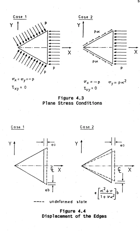
[image:65.557.52.516.37.799.2]58
Figure 4.3
Plane Stress Conditions
Case 1 Case
2
eb
MOM••••••••■ 11=I■
undeformed
state
Figure 4.4
here, while the first case, which is simpler, has only been included for the purposes of comparison. For both cases, the edges of the plate are considered to be simply supported, simulating the edge conditions of the panel in the space frame. Further it is assumed that the edges of the plate are constrained to remain straight even after buckling; this is necessary to maintain the conditions of symmetry (between neighbouring panels) in the space frame. Figure 4.4 shows the in-plane displacements along the edges of the plate, for the two cases considered, for an applied strain, or unit displacement, "e" normal to the base of the plate.
It may also be pointed out that, unlike the rectangular plate, which can have arbitrary loads along its adjacent sides, the triangular plate can be loaded only in a fixed proportion, due to the restriction of statics. The in-plane displacements of the edges, or the linear components of the strains in the X and Y directions are thus constrained to retain the same proportion as that of the plane stress condition in the pre-buckling stage.
4.2 Expressions for the Displacements
The displacements u, v, and w for the plate, in the X, Y, and Z directions respectively, are expressed in the following form:
U = C.,g,(x,y) -ex ; v = C,
c ",h,(x,y) + t oey for i = 0 to N
where,
gi(x,y) = cos(k1rx/2a)cos(liry/2b) - cos(lex/2a)cos(k1ry/2b) hi(x'y) = sin(yrx/2a)sin(11ry/2b) - sin(lex/2a)sin(kiry/2b) f(x,y) = cos(mirx/2a)cos(ney/2b) cos(n1wx/2a)cos(m1ry/2b)
(4.2)
In these expressions k1,11,m1 and ni are odd integers such that kifli and
mi
fni.
The ratio of the linear strain component in the Ydirection to that in the X direction, to, is obtained by plane stress
analysis in the pre-buckling stage, for case 1 & 2 respectively, as,
t0 =
-1
and t0 = (a2 + v) / (1 + v &2) (4.3)where
e
= tan
0
=
b/6 and v is the Poisson's ratio, taken to be 0.3.The functions g, h and f are chosen so that they vanish
along the boundary of the plate. Although h is zero at the points
(a,0), (a,+b), and its integral over the edge x = a vanishes, it has
non-zero values at the intermediate points; so that the condition of v
being linear along this edge is only approximately satisfied. Apart
from this, the functions u, v and w completely satisfy the geometric
boundary conditions, namely that w should vanish and the in-plane
displacements be linear along the edges of the plate. It may be
mentionedthatthefunctionsf(x-a) used for the lateral deflection
w, are essentially of the same form as that used by Wakasugi for the
right isosceles triangular plate", in which case, they satisfy both
the boundary conditions of simple support exactly. A similar function
4.3 Strains and Stresses in the Middle Plane
The strains and stresses in the middle plane of the plate are given
by,
1
2
u
=
,x
2 ,x
+ -
Wx =
(1-v2)
x
y]
1
2
E = V
Y
,y
+
x]
(1-v2) [ Y
7 =
xy
u +v +w w
,y ,x,x ,y
xy
2(1+v) 7xy
=The normal and shear stresses along the edges x = +
a y ,are given
by,
en
=
eycos2
0 +ex sin
2
0 +2 r cos
xy
0sin
0. 2
1
=
r
-
a 1 cos
0
sin
0
+ r
[cos20 - sin ej
sn
L
y xj -xy
The boundary conditions to be satisfied by the stresses in the
middle plane, for cases 1 and 2 are respectively as follows:
Case 1
(i) Shear is zero along the three edges of the plate.
(ii)The sum of the X components of the normal stresses along the
equal sides of the plate is equal to the sum of the normal
stresses along the base of the triangle.
Case 2
62
(ii) The X component of the sum of the shear stresses along the equal edges and the sum of the normal stresses along the base of the triangular plate should add up to zero.
Noting that the functions chosen for u , v and w are such that the shear stresses are always zero along the base and that the functions are symmetric about the X axis, these boundary conditions may be expressed as follows:
Case 1
(i) f
a a
7-__I dx = 0 (ii)
r
f
x
dy - tan0
f a_i dx = 0 0 n y=ax x=a 0 "Iy=axCase 2
fa b a
Jo
gn
1 dx = 0 (ii) Jo'xI dy+s
0
rn
Idx = 0(i)
0 I= s
I
y=ax
xa
y=ax4.4 Determination of Buckling Modes
The change in the potential energy of the plate when it buckles may be expressed as V = Ub - W , where Ub is the strain energy due to bending of the plate, given by
U = b
and 2
W is
[[w + w ,xx ,yy
the work done 2
- 2(1-v) [1,4 w ,xx ,yy - w 2 ,xy ]1 dx dy
by the stresses in the middle
(4.4)
63
w _ -t 2 [ffx ,x 2 + g w 2] dx dy
y ,y (4.5)
In eqn.4.4, the modulus of rigidity of the plate D = Et3/12(1 - v2). Expressing the lateral deflection of the plate as w = Ai fi(x,y), where the functions fi(x,y) are given by the third of eqns.4.2, the total change in potential energy is obtained as,
v
=
2
i
f
A.A.[f + f [f +f dx dy 1.7 do( ,YY ,xx YY;
-
i
f
AiAj[a f x ,xi ,xj f . +g f .f .] dx dy y ,yi ,yjJ
J
f.f ,xyl ,xyj .dxdy cancel out and therefore do not appear in the bending energyterm.Minimizing1tw.r.t.theamplitudeparametersA.we get,TAT = D jAjjiff XX
f
,YY][f,xx+ fay] dx dy+ t Ajfflax f,xi f,xj + ay faifaj] dx dy = 0 (4.6)
In the above set of equations the stresses 0'
x and ay are given by the
plane stress relations tYx = - p and x /Oy = (V - t0 )/(1 - Vt0' ) which
are applicable to both the loading cases considered. Expression 4.6 thus represents a system of homogeneous equations for the solutions of which can be treated as an eigen value problem. The eigen values represent the buckling stresses and the corresponding eigen vectors the buckling modes.
It may be observed that the functions fi(x,y) representing the
deflection w do not satisfy the moment boundary condition of simple
support, namely that w,XX+ w,yy = 0, along the edges of the isosceles triangle. (This condition is satisfied exactly only for the particular
case of the right isosceles triangular plate.) However minimization of
the potential energy of the plate, represented by eqns.4.6, determines
the buckling mode for the triangle such that this second boundary
condition is approximately satisfied. This may easily be observed by
looking at eqns.4.6 in its variational form. Noting that the function
w as well as its derivatives in the tangential direction vanish along
the boundary, we may write the variation of the potential energy V in
its expanded form (Ref.69, pages 88-91) as
5V = D
f
f
f
w
,xxx 2w ,xxyy + w,yyyylOwdxdy - xw
a w PwdxdyJJL
x ,xx y ,yy+ Df[w + w PF-,xx ,yy an 41ds = 0 (4.7)
Eqn.4.7 represents the generalized Galerkin's equation for
an isotropic plate. The first two integrals represent minimization of
the error in satisfying the governing equation over the entire area of
the plate. The third, which is to be integrated along the boundary,
represents minimization of the error due to the unsatisfied boundary
condition with respect to variations in the slope (dw/dn) normal to
the boundary of the plate. Eqn.4.7 is essentially the same as eqn.4.6,
since they are both expressions of the same principle. Both yield the
same results, and in either case the buckling modes are determined so
the plate. Thus the critical stress values obtained by the solution of eqn.4.6 for Case 1 in this study are identical to those obtained by solving eqn.4.7 in Ref.68 for isotropic isosceles triangular plates under uniform compression.
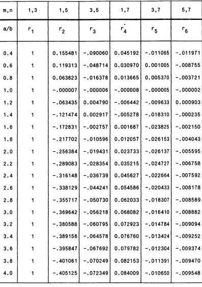
• For the present analysis, the deflection w of the triangular plate was represented by six terms of the functions f i (x,y), with values of (m,n) = (1,3),(1,5),(3,5),(1,7),(3,7) and (5,7). The primary buckling stresses obtained by the solution of eqns.4.6 are plotted (in solid lines) in Figure 4.5 as a function of a/b, for the two loading cases. The ordinate of the figure is the non-dimensionalized buckling coefficient p o which is given by the relation
ta2 t b2 PO = r2D Pcr =
x2a2D Pcr
(4.8)
Also indicated with crosses in the figure, for comparison, are the results obtained using the exact deflection functions of Wakasugi 65,66 for the right isosceles and the equilateral triangle. The broken lines in the figure are the plots of the buckling coefficients corresponding to the second buckling mode. It may be observed that the latter values are at least two times higher than those of the primary mode.
To indicate the convergence of the solutions obtained, the values of 13 0 for the second loading case obtained by the addition of each successive term are tabulated in *Table 4.1, for two types of ,
triangles: the right isosceles (a = 1) and the equilateral (a
It may be observed that the degree of convergence is much higher for the right isosceles triangle (wherein the functions used for w satisfy both boundary conditions exactly) than for the equilateral triangle.
The critical compressive strain e cr is given by
e
(1 - v
2
)
=
cr E(1 - vt
0 ) Pcr
which may be expressed in non-dimensional form as
[a 1 e0 = t]
2 e cr
(4.9)
(4.10)
The numerical values of p o and the non-dimensional critical strain e 0 corresponding to the primary buckling mode are presented in the first two columns under case 1 and 2 in Table 4.3 for reference.
4.5 Evaluation of the Amplitude Parameters of the Buckled Plate
40
32
8
%.0
7 2 D /1A
/ / / / / Pcr = 2 Po
a t
1
po SEC= MODE - CASE 1
p SECOND MODE - CASE 2
/
/
/
poPRIMARY MODE - CASE 1
po PRIMARY NCOE - CASE 2 / / / / / / / /
_
IS
101W1
1
1
1
1.8
a/b
2.4Figure 4.5. Buckling Coefficients
for the Isosceles Triangular Plate
24P
o
18
.8 3.2 40
1.5
A =Boti(n0-1)eo
1.0
Case 1
0.0
0.0 1.8
a/b
2.4Figure
4.6.
Constant Bo
for the Amplitude of Lateral Deflection
eo
.5
in the following manner.
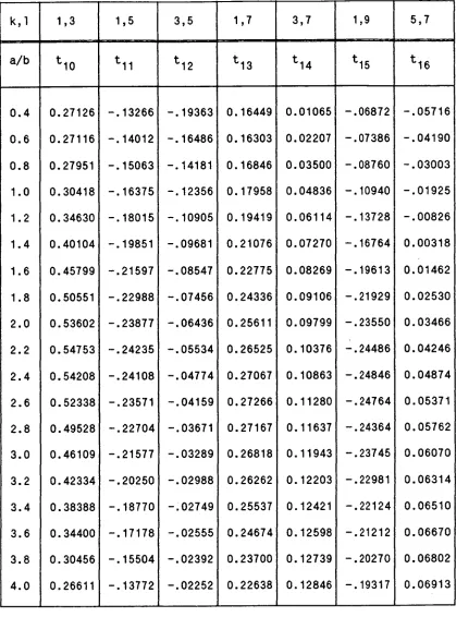
The middle plane stresses (see secn.4.3) are first expressed in terms of the functions representing the displacements u, v and w (eqns. 4.1 and 4.2). Then by satisfying the boundary conditions (i) and (ii) for the middle plane stresses, the first constants C10 and C20' in the functions u and v respectively, are obtained in terms of the remaining 2N constants in those functions and the amplitude A of the lateral deflection. They may thus be expressed as
C10 = b 1 []A + b 1,1,1 C1i + b 1,2,i C2i
and
C20 = b 2 []A + b2,1,1 C1i + b2,2' i C2i a
i i
(4.11)
In eqns.4.11, i takes values from 1 to N only. b01, b02, b1,1,1 , b1,2,1 , b2,1,1 & b2,2,1 are constants obtained by integration. The amplitude A and the 2N unknown coefficients Cli , C2i are determined by minimizing the total strain energy of the plate with respect to these unknown quantities. The total strain energy of the plate is given by U0 = Ub + Um , where Ub is the bending strain energy, given by eqn.4.4, and Um is the energy due to the strains in the middle plane, which may be expressed as
Urn m
E t
2(1-v2)if [E2 4. e2 4. 2v e e 4. (1-v) 2
7- ] dx dy
xy xy2 xy (4.12)