City, University of London Institutional Repository
Citation
:
Kechagias-Stamatis, O., Aouf, N. ORCID: 0000-0001-9291-4077 and
Richardson, M. (2016). 3D Automatic Target Recognition for Future LIDAR Missiles. IEEE
Transactions on Aerospace and Electronic Systems, 52(6), pp. 2662-2675. doi:
10.1109/TAES.2016.150300
This is the accepted version of the paper.
This version of the publication may differ from the final published
version.
Permanent repository link:
http://openaccess.city.ac.uk/22103/
Link to published version
:
http://dx.doi.org/10.1109/TAES.2016.150300
Copyright and reuse:
City Research Online aims to make research
outputs of City, University of London available to a wider audience.
Copyright and Moral Rights remain with the author(s) and/or copyright
holders. URLs from City Research Online may be freely distributed and
linked to.
Abstract—We present a real-time 3D Automatic Target
Recognition approach appropriate for future Light Detection and Ranging (LIDAR) based missiles. Our technique extends the Speeded-Up Robust Features method into the third dimension by solving multiple 2-dimensional problems and performs template matching based on the extreme case of a single pose per target. Evaluation on military targets shows higher recognition rates under various transformations and perturbations at lower processing time compared to state-of-the-art approaches.
Index Terms—3D ATR,Hough pose clustering,LIDAR, Real-time, Target recognition
I. INTRODUCTION
ilitary Automatic Target Recognition (ATR) systems and specifically future Light Detection and Ranging (LIDAR) missiles with ATR capabilities, must have a high true and low false positive recognition rate in order to avoid incorrect targeting and collateral damage. The missile data acquiring subsystem (seeker) and the guidance section of a LIDAR based missile need to have low cost, low demand upon computing resources and resistance to obscuration smoke or camouflage type countermeasures. In addition, the image matching system needs to cope with the change of scale as the missile closes on the target as well as the change in orientation as the missile maneuvers during target acquisition and tracking phases of the engagement. Moreover, the recognition procedure has to be real-time. Hence, the processing time afforded to a missile to perform ATR under the aforementioned demanding conditions is quite strict. These demands take place in a noisy battlefield environment with a great number of non-targets (clutter) such as non-military vehicles, ground, trees etc. that the missile has to avoid. In terms of hardware, the computing and sensor unit need to fit into the missile’s guidance section, which requires a high packing density for the sensor and process electronics.
Existing [1] and future expansions [2], [3] of ATR algorithms incorporated in missiles operate in the Infrared (IR) domain taking advantage of the thermal signature of the target. These approaches have a major disadvantage. Specifically,
This work was supported by MBDA UK under grant HP29012014. The authors are with the Centre of Electronic Warfare, Cranfield University Defense and security, Shrivenham, SN6 8LA, UK
(e-mail: {o.kechagiasstamatis, n.aouf, m.a.richardson}@cranfield.ac.uk)
they have a large template size to gain a higher recognition rate that rises substantially their memory storage needed onboard the missile and the template matching time. Moreover, their performance highly dependents on the target’s pose and therefore constrained by the number of viewings per target stored as templates to perform the matching. An additional disadvantage is that the templates need to be up-to-date from a priori information and that warm and cold images of the target set must be stored. Warm images present the hot areas of the target, e.g. exhaust, brighter than the corresponding colder ones. Cold images are the complement version of the warm images.
Object recognition in 3-dimensions (3D) is an active research area as it presents numerous advantages over its 2-dimensional (2D) counterpart. Indicatively, 3D data take advantage of the geometric properties and the underlying structure of an object. These are more informative compared to 2D image information [4] providing enhanced object recognition capabilities. In addition, features extracted from the 3D domain (data) are less affected by illumination variation and pose changes [5], [6].
With respect to future LIDAR based missiles, 3D ATR can
improve weapon effectiveness against camouflage,
concealment and deception techniques because the laser beam has a small spot size, which enables penetration of sparse structures. In addition, the short wavelength in which laser scanners operate, provides high-resolution data and the capability to acquire details of the target reinforcing recognition applications.
Simply transferring common 3D pattern recognition approaches from the computer vision area to future LIDAR based missiles is not an optimum solution, as these methods do not meet time response criteria, computational limits and memory requirements to store the database templates. Missile based ATR algorithms have to achieve simultaneously a high recognition rate and real-time performance in order to handle the missile’s high velocity and agility. An advantage of military-oriented ATR algorithms is that they do not aim at registering the target into the scene or determining its pose, but are restricted to decide if the tracked object is a target of interest. In the latter case, the LIDAR and associated ATR must keep lock while the pose, scale and degree of obscuration are changing. If the tracked object is not of interest, the seeker has to break its tracking loop and search for the correct target.
The solution we propose to the defense industry is an extension of the state-of-the-art Speeded-Up Robust Features
3D Automatic Target Recognition for Future
LIDAR Missiles
O. Kechagias-Stamatis, N. Aouf and M. Richardson
(SURF) algorithm into the third dimension. Our approach named the SURF Projection Recognition (SPR), significantly reduces the processing time compared to the existing 3D object recognition techniques and mainly meets time response restrictions of LIDAR based missiles. SPR accomplishes the speedup by transforming the recognition problem from the 3D space into multiple ones in the 2D space. Furthermore, unlike common ATR approaches, the proposed technique reduces the database size to only one pose per target providing a twofold advantage. Template matching time and memory requirement to store the database are substantially reduced by shrinking the database entries by two orders of magnitude compared to a multi-pose and multi-azimuth approach that is the norm in ATR systems. In conclusion, SPR is fast to execute and is robust to a number of rigid transformations and perturbations applied to the target.
The rest of the paper is organized in the following sections. Section II presents a literature review of the existing 3D pattern recognition algorithms. Section III refers to the proposed approach, the SPR, and introduces the point cloud manipulation and range image creation, the SURF algorithm, the Hough pose filtering procedure, the simulation of viewing dependent point clouds, and finally a synopsis of the proposed ATR workflow. Section IV deals with the evaluation results on two uncluttered datasets, on several forestry scenes, and compares and contrasts our approach to the Rotational Projection Statistics (RoPS) algorithm. Finally, Section V concludes the paper.
II. RELATED WORK
3D object recognition techniques can broadly be divided into global and local feature based. Global feature based techniques process the object as one entity providing adequate performance in target class recognition. A prerequisite for their implementation is the segmentation of the object from the scene. An example of that technique is the geometric 3D moment [7]. Local feature based techniques describe local patches of the object and provide an appropriate solution to detecting partially visible objects in occluded scenes, object registration, pose estimation and afford good performance in object recognition. Some intelligence-based data, providing unique object features will greatly assist this. Due to these advantages, many pattern recognition attempts have been made in the 3D local feature based domain with the trend being an extension of the already mature 2D pattern recognition algorithms to entirely new 3D approaches or solutions based on range images.
The main contributors in the extension of 2D to 3D feature based pattern recognition are THRIFT [8], 3D SURF [9], 3D Harris [10] and 3D Features from Accelerated Segment Tests (3D FAST) [11]. The drawback of these approaches is that a LIDAR sensor provides non-volumetric data. Hence, additional processing time is required to transform the data into voxels with the total computational time exceeding the constraints of a military real-time application. Even the fastest 3D SURF requires approximately 8s for pattern recognition on
a high-performance computer for a cloud of 50,000 points and 2003 voxels [12].
Pure 3D approaches are applicable directly to the point cloud or to its mesh. If the mesh information is required, some extra time is needed to calculate the mesh itself, since LIDAR provides only the relative distance between the target and the sensor. Among the most well-known algorithms for 3D recognition are Signatures of Histograms (SHOT) [13], Spin Images [14], Intrinsic Shape Signatures (ISS) [15], Rotational Projection Statistics (RoPS) [16] and Tensor [17].
Range image pattern recognition is based on 2D projections of a 3D object on a defined reference frame. Although it is a 2D approach, incorporating information from the 3D world, it has not been extensively investigated. In recent applications, the SURF [18] and the Scale Invariant Feature Transform (SIFT) [19] are applied to previously pre-processed range images. Indicatively, Lei et al. [6] convert the raw range image to a multi-level B-spline approximation to achieve a detailed and smoothed image. Onto those images, they applied SURF. Even though this approach works well in face recognition, it is quite time consuming and exceeds the constraints of a military application. Bayramoglu and Atalan [20] as well as Lo and Siebert [21] convert the range image into its shape index representation to enhance the details and then apply SIFT. Although this method achieves correct recognition, its out-of-plane rotation invariance is limited. Recent approaches are the Normal Aligned Radial Features (NARF) [22] and the Binary Robust Appearance and Normals Descriptor (BRAND) [23]. Some of the 3D algorithms like BRAND or the Color SHOT (C-SHOT) [24], which is a variant of SHOT, combine depth and texture information to achieve a higher performance.
The standard, but extremely time-consuming policy in 2D pattern recognition problems is to create a database with a collection of templates representing possible viewings of each potential target. The number of viewings per target is inversely proportional to the invariance of the local features. The invariance should be such to bridge the gap between the templates. Gray et al. [25] in their successful ATR approach in the infrared domain, create a database consisting of 12 azimuthal viewings of each of the four naval targets. In total, they have a database of 48 viewings on which SIFT based strategy is applied. This type of approach in the 3D case demands 123 viewings per target (12 viewings per pitch, roll and yaw rotation) leading to 6912 different poses for the same number of targets. Assuming that each pose provides at least 20 keypoints in a low-resolution image, the database contains a list of 138,240 entries that have to be matched with the ones detected in the scene. Instead of that typical approach, we use only one pose per target in the 3D domain leading to three orthographic projections in the 2D domain. For the same sized database instead of 6912 different poses, our proposed approach needs only 12. Hence, both matching time and memory requirements to store the templates are considerably reduced.
geometric fitting [27], multi-hypothesis sequential testing [28], the Baseline Processing Pipeline [29] and the Projection Density Energy based solution [30]. Although Spin Images perform well in target recognition, their calculation time exceeds the constraints of a LIDAR based missile. Also, as the target becomes sparse or noisy, the performance of Spin Image degrades [31]. Geometric fitting decomposes the scene into a set of rectangles, based on the assumption that man-made objects are approximately rectangular in nature. Multi-hypothesis sequential testing deals with multi-Multi-hypothesis sequential probability ratio tests, motivated by Bayesian settings. In this approach, the recognition time per target is reduced compared to that of the Spin Images but still beyond that of military type requirements. Although the Baseline Processing Pipeline is within time response constraints, it presents a number of strict assumptions difficult to fulfill in a battlefield scenario. The Projection Density Energy based recognition algorithm, although being very fast, it assumes that the target is already segmented from the scene.
The computer vision community has made many positive attempts in 3D object recognition but military type recognition in real-time combined with the hardware constraints of a missile system is still challenging. Another drawback is that current computer vision approaches aim at high quality feature matching for 3D image registration and pose estimation. The requirement for a real-time 3D ATR LIDAR based missile application is to achieve a lock-on to the preferred target with a high confidence level neglecting registration and pose estimation capabilities. Hence, considering that:
Military-oriented ATR algorithms can rely on state-of-the-art 2D ATR methods
State-of-the-art 2D ATR methods can be implemented on range images
A 2D problem is less complex than a 3D one
we propose a 3D ATR algorithm based on multiple range images. Its main characteristics are the high recognition performance, the sufficiently shorter processing time and the reduced memory demand, that may be appealing to the defense industry. SPR lies on the range image pattern recognition category and extends the concept of our previous work [30] which decomposes the recognition problem from the 3D space into multiple 2D ones. Specifically, in this paper we remodel the recognition problem from the highly complex 3D space into multiple 2Ds in order to gain processing time speedup while in parallel we exploit the appealing advantages of the local feature recognition strategy. In addition, we further reduce processing time by restricting the templates for matching to a single pose per target.
III. PROPOSED APPROACH
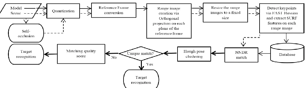
Current section describes thoroughly the online and the offline pipeline of SPR both for the model and the scene. Fig. 1 presents a schematic of the proposed approach.
A. Point cloud manipulation and range image construction
Given a point cloud 3
P , each point of the cloud can be
represented as Pu( ,i j ku u, u) ,T u
0,M
where M is the total number of points. Initially the raw point cloud is uniformly quantized with a quantization step Δ in order to reduce the amount of points and hence overall processing time:
12 u
qu u P
P sign P
(1)
Each point Pqu,qu
0,L of the quantized cloudcontaining L points withLM, is then transformed from the missile reference frame
i j k, ,
to an external world basedreference frame
X Y Z, ,
by exploiting information from the missile’s gyroscopes, which provide the pitch (θ), roll (φ) and yaw (ψ) angles. Both reference frames are centered at the missile seeker. Additionally, we choose the
X Y Z, ,
reference frame as external world based in order to reduce complexity and improve time efficiency. The latter is achieved because the
X Y Z, ,
reference frame does not align witheach target in the scene individually, but with the real world coordinate system, that includes both the missile and the scene.
The coordinates of each point Pqu are transformed from the missile reference frame
i j k, ,
into the world basedreference frame
X Y Z, ,
by applying the Euler – Rodrigues rotation formulas:cos( ) sin( ) (1 cos( ))
cos( ) sin( ) (1 cos( ))
cos( ) sin( ) (1 cos( ))
y
x
z
R I i i i
R I j j j
R I k k k
(2)
for the x-axis and equally for the y-axis and the z-axis: 0
0 0 x
k j
i k i
j i and 2 2 2
i ij ik
i i ij j jk
ik jk k
(3)
Where, Iis the identity matrix, i xis the cross product
matrix of I and ii is the tensor product. The transformation of the initial coordinates of each quantized point Pqu from the missile to the world based reference frame provides a new set of points P'qu:
' ' ' ' qu qu qu qu qu qu qu x x
P y R R R y
z z
(4)Where xqu,yqu,zquare the quantized coordinates in the
i j k, ,
missile reference frame and xqu',yqu',zqu' are the corresponding coordinates in the
X Y Z, ,
world reference frame.The projection of each point P'qu to every plane of the world based reference frame is described by the orthographic projection matrix Portho by zeroing the appropriate binary remapping coefficients c c c1, ,2 3
0,1 from the 3D to the 2Dprojected. For example, ifc1 c2 1andc30 then the X-Y
projection is received. In parallel, the point cloud is translated to the origin of the world reference frame, set at the missile’s seeker, by applying the proper translation coefficients t t t1, ,2 3.
The coordinates P of the orthographically projected point cloud after being quantized, rotated to the world based reference frame and translated to the origin, are given by:
1 1 1
2 2 2
3 3 3
0 0 0 '
0 0 0 '
'
0 0 0 '
1 1 0 0 0 1 1 1
qu qu
qu qu
ortho qu
qu qu
x t c x t
y t c y t
P P P
z t c z t
(5)
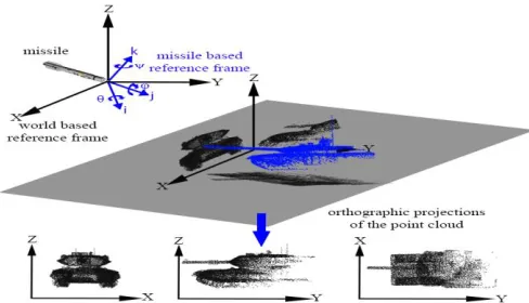
where xqu,yqu,zqu are the coordinates of the orthographically projected points on the XZ, YZ planes. The three orthographic projections (fXY, fXZ, fYZ) are range images, which are simplified versions of the 3D point cloud P'qu. In these images, the depth value of each plane i.e. fXY(xqu,yqu)zqu is unique and represents the distance between the target and the LIDAR seeker. Fig. 2 presents an illustration of the reference frame conversion and the 2D projections.
The size of each projection is variable depending on the amplitude of the point cloud values after quantization. During the final pre-processing step, before the keypoint detection and description stage, we rescale the range images into a fixed size of 128pixels*W or W*128pixels, where W is the width of the projection, with W≥128. This strategy assists at maintaining the aspect ratio [32] and avoid image distortion. In parallel, the fixed sized projections aim at further reducing the processing time and improving the recognition performance over a greater range of scales.
Although the quantization process improves the processing time, it inevitably leads to information loss that can downgrade the recognition quality. Thus, a balance between recognition performance and the time response is crucial.
B. Local Features
Based on the scale space theory, Bay et al. [18] proposed a combination of a 2D keypoint detector and descriptor under the name SURF, as a faster counterpart of the popular SIFT [19]. Initially SURF creates a response map and detects points of interest based on the local extreme of the approximated
determinant of the Hessian (Happrox):
2
arglocalmax Det H( approx) arglocalmax DxxDyy(0.9Dxy) (6)
where D D Dxx, yy, xy are the discretized versions of the corresponding Gaussian second order kernel convolved with the projection of interest, e.g.:
[image:5.612.59.559.51.196.2]2 2
| ( ) | 1
( , , ) ( ( ( )) ) * ( , )
2
xx qu qu qu qu
qu
g
D x y sign g f x y
x
(7)
where f is the 2D orthographic projection, g is the Gaussian kernel of standard deviation σ and Δ the quantization step.
In our SPR solution and during the keypoint detection phase on each of the three range images, SURF is based on three octaves and four scale intervals per octave. The threshold of the approximated determinant of the Hessian is set to 10-5.
The quantization step Δ applied to the initial point cloud is crucial as it affects the number of detected keypoints and the overall performance. Specifically, as the quantization step Δ decreases, SURF detects more keypoints as shown in Fig. 3. In contrast to the B-spline [6], this pre-processing step has almost no time cost.
The SURF descriptor is based on Haar wavelet responses, which can be efficiently calculated by exploiting integral images. In our approach, the default 64 elements long descriptor is used. Keypoint matching is carried out via the Nearest Neighbor Distance Ratio (NNDR) criterion [19], which was set to 0.6.
According to the developer of SURF, the latter has a stable performance in the scale range from one up to 2.5. However, beyond that region repeatability scores are dramatically decreasing. ATR algorithms that have to exceed the above restriction include a training set with representations of the expected target in various scales. In this case, the size of the database and the matching time are significantly increased.
In our approach, the recognition capability over several scales is increased by resizing both the template’s and the target’s range images to a fixed size of 128pixels*W or W*128pixels, where W≥128. The aspect ratio is preserved in order to avoid image distortion and the resizing procedure is approximated by nearest-neighbor interpolation for time efficiency. In addition, the database includes a set of potential target templates using small sized range images, simulating
the target being at the furthest range or in equivalence, in the smaller scale that the sensor can detect. This methodology provides a number of advantages:
Scale variability can exceed the restriction of 1 - 2.5 without increasing the size of the database.
As the missile moves towards the target, the size of the target increases with a direct influence on the number of the detected keypoints and the substantial growth of the processing time to detect, extract and match the features. In our solution, resizing the range images to a small and fixed size, regardless of the true size, provides a predictable number of keypoints in less time if an efficient method like nearest-neighbor interpolation is used.
SURF achieves most matches when both the target and
the template are in the same scale. By resizing, as in our approach, the target’s range images to a fixed size, the number of matches is maximized maintaining a relatively stable and high recognition performance.
Additionally, as the missile – target range reduces, each range image of the target is downscaled creating a smoothed version neglecting some of its details. The smoothed images allow the robust recognition performance even under the thermal noise of the sensor or sparse representation of the target.
C. Hough Pose Filtering
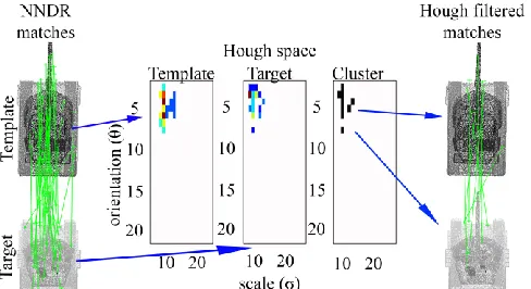
Even after matching the SURF features outliers may still exist. Outliers can be discarded by applying a coarse Hough Pose clustering [19]. This filtering method is based on a voting process where the already matched keypoints are re-matched in a Hough space over scale σ and rotation θ [33].
Specifically, for the SPR, the matched keypoints of the target and each template are plotted on a 2D accumulator plane where the x-axis represents the scale bins and the y-axis the orientation bins in which the matched keypoints are detected. An accumulator plane is a plane where each keypoint occupies a bin based on its σ and θ combination where it is detected. So each matched keypoint from the NNDR stage, votes for a single bin in the accumulator plane of the target and the template respectively. Finally, a cluster of
matches is created as the intersecting bins of both accumulator planes. These intersecting bins correspond to the refined matches. In case more than one matched pair of keypoints occupies the same bin, only the first pair is considered as being valid. In order to reduce discretization errors, the scale bins have a size of one and a range from 1 - 20 and the rotation bins are of size 15° in the 0° - 360° range.
Fig. 4 presents an example where the NNDR threshold provides 76 matches between two dissimilar targets. Each matched pair depending on the scale σ and orientation θ occupies a single bin in the template and the target accumulator plane in respect of the Hough space. The intersection of both accumulator planes creates clusters that provide a refined set of matched keypoints reducing the mismatches by 91%.
D. Simulating viewing dependent point clouds
All freely available models are in a 3D ideal representation while in reality the LIDAR seeker can only receive a part of the target depending on its pose. Typical land based missile applications rely on top attack and side view poses in order to defeat the target where armor is thinnest. Thus, the Hidden Point Removal (HPR) [34] algorithm is used to create self-occluded point cloud views emulating realistic views of the LIDAR missile seeker. HPR includes three stages. Initially, it remaps the coordinates of each point Puof the raw point cloud. This is done by exploiting an imaginary a ray connecting each point Puand the viewpoint. The remapping is a mirror image of the raw point cloud as observed from the viewpoint, which is set at the LIDAR seeker of the missile. The next step incorporates the projection of the remapped point cloud onto a sphere of radius R centered at the missile seeker. This procedure is called “spherical flipping” and the resulting point cloud consists of the Psfu points:
2( ) u
sfu u u
u P
p P R P
P
(8)
[image:6.612.49.293.49.189.2]In this work, the radius R is automatically calculated as suggested by Alsadik, Gerke and Vosselman [35]. Finally, the convex hull of the resulting point cloud, associated with a weight factor aufor each point of the cloud is given by:
Fig. 2. Outline of the transformation from 3D to multiple 2D. M1A1 Abrams Main Battle Tank (MBT - red) as observed from the missile’s reference frame (blue). The MBT is quantized and transformed to the world based reference frame (black) after incorporating information from the gyroscopes of the missile. Range images are created from the projection of the MBT onto the planes of the world reference frame.
[image:6.612.315.566.560.703.2]| | | |
1 1
| ( : 0) 1)
sfu sfu
P P
u sfu u u
u u
a p u a a
(9)Summarizing, a point Pu of the raw point cloud is considered as visible, only if its spherical flipped form Psfu is on the convex hull. The HPR concept is shown in Fig. 5.
E. ATR workflow
The SPR procedure can be split into an offline and an online part. Offline, a database of potential targets to be recognized is created. The ideal 3D point cloud of each target is quantized and orthographically projected on the three main planes XY, XZ, YZ of the
X Y Z, ,
external world based reference system and then resized to a fixed size. SURF is then applied on the range images created. Each target is represented by three range images and for each point of interest detected on those range images the coordinates, scale σ, orientation θ, and the SURF descriptor are stored. During this stage, it is important to align in 3D the point cloud of each template in the canonical pose. The online procedure is the same as the offline one, except that HPR is applied in order to simulate the self-occlusion effect. The extracted SURF keypoints are then matched via an NNDR criterion and the template that receives the most matches over all planes is considered as the recognized target. The NNDR criterion is set to 0.6 such as tobalance recognition performance and robustness to
perturbations like noise and sparsity. In case more than one template provides the same number of maximum matches, we establish a matching quality criterion. The quality of each match is based on the average difference of the responses of the matched SURF keypoints as given from the approximated determinant of the Hessian. The template providing the smallest difference to the target over the three planes is chosen as the recognized one. The processing flow of SPR is graphically presented in Fig. 1.
[image:7.612.50.294.51.184.2]Matching time and memory demands are further reduced as the database consists of SURF features obtained only from three range images. The later result from the projection of each potential target, which is in its canonical pose and is viewed from 45° angle in any axis.
Fig. 6 presents a matching example. It shows the case where a MBT as the target is in 60° rotation in pitch, roll and yaw, self-occluded and at scale x2s and is matched with the database consisting of two models (one similar and one dissimilar - different class of MBT) which are in their canonical pose, without any occlusion and at scale s. Each target and template are orthogonally projected to the planes of the world reference frame in order to create three distinct range images. SPR successfully matches the target with its corresponding template providing in total 28 matches over the three projection planes. On the contrary, for the dissimilar target (different class of MBT) SPR provides only 9 matches. These mismatches mostly occur at the barrel of the MBT as both templates possess one. The availability of more detailed target set data, which gives turret shape or road wheel configuration, would assist in further enhancing the discrimination.
IV. EXPERIMENTS
The effectiveness of SPR is evaluated by a number of experiments on military targets of the Princeton Shape Benchmark [36] database and on a set of military ground surface targets [37] with both inter and intra-class variation. The term inter-class variation refers to recognizing different classes of targets e.g. a fighter aircraft from a warship. The intra-class variation refers to recognizing different types of the same class, e.g. a M1A1 Main Battle Tank (MBT) from a T-90 MBT.
Each target is rotated in pitch, roll and yaw in the 0° - 360° region with an increment of 30° neglecting non-applicable poses. We define as non-applicable poses those that are not likely to occur, e.g. the LIDAR seeker of the missile cannot observe a warship from inside the sea. We select a 30° rotation increment due to the limit of the affine transformation that SURF can manage [18].
Experiments comprise of a number of combined rigid transformations and perturbations such as thermal noise and uniform sparse representation of the target. Trials are performed while the target is at scale s and x10s. Initial
experiments assume uncluttered targets, while more
complicated scenarios are examined in Section IV-C.
According to open source data, the processing power of a missile is in the order of a Quad Core PowerPC G4 from the 74xx processor family and ATR algorithms for missiles are implemented in C/C++ [38]. The SPR is developed in MATLAB 2015a and the processing platform for all trials is an AMD Dual Core 2.1 GHz laptop exploiting a single core.
Although our developing scheme differs in relation to a final missile implementation, affecting the measured processing time during trials, we consider that SPR meets the time response criteria. Specifically, the efficiency of C/C++ compared to MATLAB is in the range of x9 – x500 [39], [40] and the processing efficiency of a missile processor is x2.5 [41] compared to our platform. Hence, the overall processing gain of a final missile implementation is x22 up to x1250. That gain increases even more if ordinary processors are
substituted by Field-Programmable Gate Arrays (FPGA). According to future upgrades to the US Navy SM-3 missile, proposed by the MIT Lincoln Laboratory [38], the desired missile latency should be 16.7ms which we adopt in our paper. Considering the aforementioned processing gain due to the platform, the coding differences and the desired this latency, we set an upper processing time limit of 500ms for our developing platform. The literature suggests measuring the computational complexity in seconds [26], [28], [29]. But due to the processing time limit set and the high-speed the missile is flying at, we set the computational complexity on a millisecond basis [30].
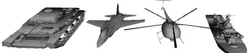
A. Princeton shape benchmark
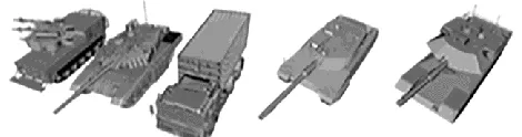
As this paper is military oriented, one representative of each military target class is used, namely a MBT, a Warship, a Helicopter and a Fighter aircraft as shown in Fig. 7.
This database has a collection of point clouds generated from CAD models with a relatively small number of points and with the planar surfaces not fully represented as they have points only at their edges. To provide a realistic representation of those models, points are populated with Poisson sampling [42] increasing their ideal 3D point cloud to 140,000 points
per target on average. In all the following experiments, we take into account the non-recognition case and self-occlusion. During the first set of trials the observation range is the generic s while in the second set of trials it is at scale x10s. Each batch of experiments includes the cases of target 3D rotation, 3D rotation combined with noise, 3D rotation combined with 50% sparse representation and finally all the aforementioned cases applied simultaneously. During all trials SPR provided high recognition performance with detailed results shown in Fig. 8.
In the first experiment, we forced the target to simultaneous rotation in pitch, roll and yaw. SPR manages 100% recognition rate in 238ms. The 3D rotational invariance of SPR is expected due to the complementary nature of the three range images.
[image:8.612.115.540.56.226.2](a) (b) (c)
Fig. 5. Hidden Point Removal (HPR) concept. (a) LIDAR based missile looking at a MBT (b) The raw point cloud of the MBT is initially flipped and projected onto a sphere of radius R. (c) On the spherical flipped point cloud the convex hull is calculated and only points belonging on the convex hull are considered as
[image:8.612.71.560.279.423.2]points of the self-occluded target.
Fig. 6. Matched keypoints between two similar (left – 28 matches) and dissimilar (right – 9 matches) Main Battle Tanks (MBT’s) in all projection planes (XZ – XY – YZ planes from top to bottom). For each plane, left point cloud represents the template and right the target.
[image:8.612.316.562.658.711.2]The next experiment incorporates sensor noise to investigate its effect on the recognition performance while the target rotates in 3D. Sensor noise mainly being thermal can be simulated with white Gaussian noise [43]. Consequently, we add to the target white Gaussian noise with zero mean and variance equal to 0.5 of the average mesh resolution (mr). The chosen variance is one of the highest values experimented in the current 3D object recognition literature [16], [44]. Although the addition of noise creates virtual keypoints that can be mismatched, the average recognition capability is still high at 95.3%. However, since SPR incorporates SURF, robustness to noise [45] is anticipated. Finally, we note that although SPR achieves a high average recognition rate, the performance of the fighter aircraft is affected. The addition of noise to the fighter aircraft modifies largely its smooth surfaces, forcing the FAST Hessian keypoint detector to create false points of interest. Hence, depending on the viewing angle, these keypoints create mismatches which lead to a performance drop.
The atmospheric conditions may attenuate the laser beam resulting in a reduced point cloud density. Hence, we evaluate SPR against 3D rotation and 50% uniform sparse representation of the target. The results show that the overall performance is unaffected achieving 99.9%. This can be explained by the fact that by resizing each range image it becomes smoother overcoming the target’s sparsity. Finally, even though inducing the target to all the aforementioned rigid transformations and perturbations simultaneously (i.e. 3D rotation and 0.5mr Gaussian noise and 50% point cloud decimation) SPR still provides a 94.5% recognition rate. Incorporating noise to the targets modifies the flat surfaces of the fighter, reducing its recognition rate in the same manner as in the pure noise case.
The same set of trials is executed with the target at scale
x10s. Increasing the target’s scale, does not affect the
recognition rate of SPR (Fig. 8). As expected, the influence of noise is now eliminated through the resizing procedure of the three projection planes. Therefore, the fighter’s recognition performance is unaffected by noise.
Through this dataset, the SPR solution is shown to be quite robust to target class recognition under 3D rotation combined with noise, uniform sparse representation and scale change.
The next dataset challenges the proposed technique with targets having both inter and intra-class variation.
B. Surface target CAD model database
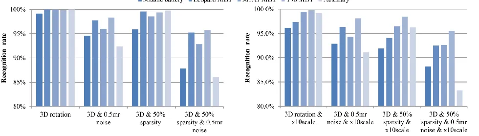
A database fitting the scenarios of the ground target case is created. It consists of a missile battery, a Leopard 2A6 MBT (GER), an M1A1 Abrams MBT (USA), a T-90 MBT (RUS) and an auxiliary vehicle the Raba H25 as shown in Fig. 9. On average, each 3D ideal target consists of 115,000 points after being populated with Poisson sampling. This database is more challenging compared to the previous one since it comprises of three similar 3rd generation MBTs while at the same time the anti-air missile battery has the body of a MBT. As previously done, in all experiments, the non-recognition case is considered and self-occlusion via HPR is taken into account.
Overall, SPR maintains its high recognition performance during all trials with detailed results presented in Fig. 10. At scale s, with self-occlusion, SPR manages for the 3D rotation case 99.8% in 469ms. Compared to the Princeton Shape Benchmark, the processing time has increased because this database is larger and has more complex targets, which provide more keypoints that have to be matched.
In the next experiment we evaluate SPR against simultaneous 3D rotations with the addition of artificial 0.5mr thermal noise. Initially the target is at scale s. Although targets have a great similarity, SPR correctly recognizes 95.8% of the cases. The largest performance reduction is observed in the auxiliary vehicle case as noise altered its flat surfaces, creating false keypoints, which lead to mismatches. Although the recognition rate for the auxiliary reduced, SPR still achieved 92% for that target which is considered adequate.
[image:9.612.67.547.54.193.2]The following trial combines simultaneous 3D rotation and 50% uniform sparse representation of the target. The average
Fig. 8. Performance of SPR under different trials on segmented targets of the Princeton database benchmark
[image:9.612.323.558.652.714.2]recognition rate is 98.6%. The anti-air missile battery has the lowest performance (95.5%), largely because of its main body which is quite similar to the other targets.
We investigate the SPR’s performance under simultaneous 3D rotation, 0.5mr Gaussian noise and 50% point cloud decimation. Although this trial combined all perturbations and 3D rotation, SPR still achieves high performance managing 91.6% recognition rate. In this case, although the flat surfaces of the Auxiliary vehicle are influenced by noise, recognition is still greater than 85%. Considering the difficulty of the simultaneous disturbances that are applied, this performance is still notable.
Finally, we evaluate SPR under the same perturbations and transformations with the target at scale x10s. The average recognition rate of all trials is now 94.7% in 495ms showing again the strong robustness of SPR even under scale change. Similarly, to the previous trials, the flat surfaces of the auxiliary vehicle are affected by noise creating false keypoints and influencing recognition. Even in the case where we combine all perturbations and transformations simultaneously, the recognition rate of the auxiliary vehicle is greater than 83%, which is still considered notable.
The high performance and low processing time of the proposed SPR solution can be explained by the following three facts:
SPR achieves 3D rotation invariance due to the complimentary nature of the three range images.
Robustness to scale is possible due to the resizing strategy applied to each range image.
SPR can successfully handle perturbations like noise and sparse representation of the target due to the combination of the resizing strategy and the discretization applied to the point cloud.
C. Evaluation on military forested scenes
Depth variation due to the relative position of the target inside the scene is crucial for the performance of SPR. To overcome that, automatic target detection and then recognition in various forested scenes is performed by rejecting the ground and the tree tops [46].
Three forested scenes with increasing difficulty are evaluated, including a number of targets per scene and several objects as clutter. Fig. 11 presents the scenarios under
evaluation as observed from the seeker. In addition, Fig. 11 shows the top template match along with the point-to-point correspondences between the top template match and the scene.
The first scenario considers the case of a T90 MBT, which is partially occluded by a tree. Our method detects and recognizes the target in 502ms. Specifically, SPR manages to match two out of the three projections of the T90 MBT template.
In the second scenario, the scene comprises of a T90 MBT, which is occluded by trees. It is worth noting that the MBT in the scene has a different pose and scale compared to the template. Still under these conditions, SPR is able to detect and recognize the MBT in 395ms.
In the third scenario, the scene contains two targets, namely an anti-air missile battery and a T90 MBT. Both targets are partially occluded by trees and have a different scale compared to the templates. Positive detection and recognition of both targets, is achieved in 307ms. Even though in both cases a small number of mismatches occur, SPR is still capable to provide correct target recognition.
D. Comparison with the Rotational Projection Statistics (RoPS) algorithm
We compare SPR with RoPS [16], which outperforms the Spin Image, THRIFT and SHOT based recognition techniques [4]. In order our trials to be fair we compare the proposed technique with RoPS and with a faster to execute variant of RoPS.
The first trials include the RoPS recognition procedure exploiting the optimal parameters as set by its authors [47]. Specifically, we select randomly 5000 keypoints in the model object and 1000 in the scene. For these keypoints, RoPS features are calculated and then matched via an NNDR criterion. Finally, for each keypoint correspondence, the transformation hypothesis is generated. Verification of the correct transformation is performed through the Iterative Closest Point (ICP) method and then the model is segmented from the scene. Hereafter, this RoPS configuration will be named as RoPS (5000-1000).
[image:10.612.64.554.55.194.2]For a LIDAR based missile, the segmentation and pose estimation subroutines are time-consuming processes. Hence, we substitute the segmentation capability, the transformation
hypothesis generation and verification process with a matching quality criterion in order to speed up the RoPS and make it more appropriate for military type oriented ATR. This quality measure considers as the correct template match the one providing the smallest average Euclidean feature distance. This modification maintains the matching quality of RoPS and discards the pose estimation capability, which is unnecessary for LIDAR based missiles.
We consider the same experiments as in Section IV-B but restrain them to the observation scale s, as RoPS is scale dependent. RoPS (5000-1000) achieves an average recognition performance of 96.4% and the processing time per pose is 118.7s exceeding by far the time constraints of a LIDAR based missile application. The reason is the time-consuming calculation of the local reference frame and the large amount of features that have to be matched. Focusing on the average recognition capability, SPR is marginally higher than the RoPS (5000-1000) by 0.1% and most important it is 253 times faster. In in contrast to SPR, RoPS is not scale invariant, which is a mandatory demand for missile type ATR. In conclusion, SPR is more appealing than RoPS for LIDAR based missiles as it combines high quality recognition performance, processing efficiency and scale invariance.
In order to speed up the RoPS we optimized the number of keypoints to achieve a balance between recognition performance and efficiency in processing time. The equilibrium is set at matching 10 keypoints of the scene to 2000 from each model. This provides to RoPS a speedup of x23 while a notable recognition performance is still maintained. Hereafter this RoPS configuration will be named as RoPS (2000-10). We evaluated this version of RoPS under the same transformations and perturbations as in Section IV-B at scale s. On average RoPS (2000-10) achieves 80% recognition performance in 7.2s. In contrast, the proposed SPR solution gains a recognition rate of 96.5% while in parallel it
is x15.6 faster. Fig. 12 presents detailed SPR and ROPS (2000-10) comparison per target and trial. In all trial and target combination, except the combined 3D rotation, noise and sparsity for the missile battery target, SPR achieves a higher recognition rate with a large margin.
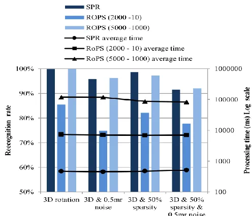
With respect to the overall performance, as a combination of recognition performance, processing time, and scale invariance, SPR is shown to outperform both variants of RoPS. Detailed comparison between SPR and both RoPS variants is shown in Fig. 13. Implementing RoPS with its default parameters provides a recognition performance that is marginally higher to SPR in the cases of combined 3D rotation and noise as well as combined 3D rotation, noise and sparsity. Nevertheless, the total processing time of RoPS is greater by a large margin, exceeding by far the time constraints of a LIDAR based missile and thus prohibiting RoPS for missile ATR applications. Limiting the number of keypoints to balance the RoPS recognition performance and processing time, SPR achieves much higher recognition rates and is still x17 faster. Furthermore, RoPS operates only on a fixed scale of the target while SPR is scale invariant which is a big advantage of the latter in a missile seeker type of application, which is the subject of this study.
Finally, SPR has a notable lower memory demand to store the templates compared to its RoPS based competitors. Specifically, SPR requires 380KB/template on average, while RoPS (5000-1000) 5,400KB/template and RoPS (2000-10) 2,160KB/template.
V. CONCLUSION
In this paper, we propose the SURF Projection Recognition (SPR) solution, which is a real-time 3D ATR algorithm robust to rigid transformations and perturbations. Specifically, SPR is robust to 3D rotation combined with scale change, thermal
[image:11.612.55.286.50.267.2]Fig. 12. Comparison per target between SPR and the RoPS (2000-10). Graph shows average processing time and bar plot the recognition performance
[image:11.612.309.557.53.266.2]noise, and sparse representation of the target. Appealing features of our approach are the combination of high recognition performance, fast execution time and low memory demand. These characteristics provide an initial step towards future LIDAR based missile seekers with Automatic Target Recognition capabilities.
SPR meets time restrictions by discretizing the initial point cloud and decomposing the 3D recognition problem into three 2D ones. In addition, the required database entries per target are reduced to the minimum of one pose per target, which is considered as a massive reduction compared to a multi pose and multi azimuth approach that is the norm in ATR systems. Further enhancements of performance are gained by using a point cloud manipulation that transforms the points from a missile reference frame to an external world reference frame. This is achieved by using data from the missile gyroscopes such as to create a triplet of orthographic projections. The resulting data are then processed using an extension of the SURF algorithm, which we name SPR or SURF Projection Recognition. SPR is tested for pose, scale and obscuration tolerance against various target types and in various scenarios. Comparative experimental results show that the SPR technique is highly processing efficient. Specifically, SPR is x17 faster than RoPS (2000-10) and x253 faster than RoPS (5000-1000). In addition, SPR has a higher recognition rate, is scale invariant and is able to operate successfully in occluded targets and forested backgrounds. Finally, SPR’s memory demand is substantially lower by a factor of x14.2 and 5.7 compared to RoPS (5000-1000) and RoPS (2000-10) in respect.
Linking the SPR’s performance to current military tactics, we conclude that:
Pose independence is an important factor for land based anti-armor missiles as they usually fly towards the target getting a downward but side-on or end-on view. In the late phase of engagement, they then have to pop-up in order to perform a top attack where the armor is thinnest. Thus, the view the seeker head sees changes when the target is very close compared to that seen at longer ranges. The SPR technique is fairly pose and scale independent and hence suitable for this.
Most anti-shipping missiles aim for the center of mass, but approach the target at wave height, thus the target is seen from this pose. If there is a rogue wave, they will perform a pop-up to avoid it, which will suddenly change the viewpoint. Linking SPR to missile gyroscope data may alleviate this problem compared to the disturbance suffered by conventional techniques.
LIDAR has good smoke obscurant penetration and if combined with ATR using SPR would probably render it fully ineffective against LIDAR SPR type seeker heads.
FPGA implemented SURF [48] and the SPR executed in C++ would be considered as future work to further improve time efficiency such as to accommodate this approach to high speed missile applications where requirement in terms of processing time is more demanding than considered in this work.
REFERENCES
[1] Kongsberg, “Naval Strike Missile - NSM.” [Online]. Available: http://www.kongsberg.com/en/kds/products/missilesystems/navalstr ikemissile/#. [Accessed: 28-Sep-2015].
[2] Gray, G., Aouf, N., Richardson, M., Butters, B., Walmsley, R., and Nicholls, E., “Feature-based recognition approaches for infrared anti-ship missile seekers,” Imaging Sci. J., vol. 60, no. 6, pp. 305– 320, Dec. 2012.
[3] Gray, G., Aouf, N., Richardson, M., Butters, B., and Walmsley, R., “An intelligent tracking algorithm for an imaging infrared anti-ship missile,” in Proc. SPIE 8543, Technologies for Optical Countermeasures IX, 2012, vol. 8543, p. 85430L–85430L. [4] Guo, Y., Bennamoun, M., Sohel, F., Lu, M., and Wan, J., “3D
Object Recognition in Cluttered Scenes with Local Surface Features: A Survey,” IEEE Trans. Pattern Anal. Mach. Intell., vol. 36, no. 11, pp. 2270–2287, Nov. 2014.
[5] Mian, A., Bennamoun, M., and Owens, R., “Three-Dimensional Model-Based Object Recognition and Segmentation in Cluttered Scenes,” IEEE Trans. Pattern Anal. Mach. Intell., vol. 28, no. 10, pp. 1584–1601, Oct. 2006.
[6] Lei, Y., Lai, H., and Jiang, X., “3D face recognition by SURF operator based on depth image,” in Proceedings - 2010 3rd IEEE International Conference on Computer Science and Information Technology, ICCSIT 2010, 2010, vol. 9, pp. 240–244.
[7] Paquet, E., Rioux, M., Murching, A., and Naveen, T., “Description of shape information for 2-D and 3-D objects,” Signal Process. Image Commun., vol. 16, no. 1–2, pp. 103–122, Sep. 2000. [8] Flint, A., Dick, A., and Van Den Hengel, A., “Thrift: Local 3D
Structure Recognition,” in 9th Biennial Conference of the Australian Pattern Recognition Society on Digital Image Computing Techniques and Applications (DICTA 2007), 2007, pp. 182–188. [9] Knopp, J., Prasad, M., Willems, G., Timofte, R., and Van Gool, L.,
“Hough transform and 3D SURF for robust three dimensional classification,” Comput. Vis. – ECCV 2010 Lect. Notes Comput. Vis., vol. 6316, pp. 589–602, 2010.
[10] Sipiran, I. and Bustos, B., “Harris 3D: a robust extension of the Harris operator for interest point detection on 3D meshes,” Vis. Comput., vol. 27, no. 11, pp. 963–976, Jul. 2011.
[11] Koelstra, S. and Patras, I., “The fast-3D spatio-temporal interest region detector,” in 2009 10th Workshop on Image Analysis for Multimedia Interactive Services, 2009, pp. 242–245.
[12] Yu ,T.-H., Woodford, O., and Cipolla, R., “A Performance evaluation of volumetric 3D interest point detectors,” Int. J. Comput. Vis., vol. 102, no. 1–3, pp. 180–197, Sep. 2012.
[13] Tombari, F., Salti, S., and Di Stefano, L., “Unique signatures of histograms for local surface description,” Comput. Vision–ECCV 2010, pp. 356–369, 2010.
[14] Johnson, A., and Hebert, M., “Using spin images for efficient object recognition in cluttered 3D scenes,” IEEE Trans. Pattern Anal. Mach. Intell., vol. 21, no. 5, pp. 433–449, 1999.
[15] Zhong, Y., “Intrinsic shape signatures: A shape descriptor for 3D object recognition,” in 2009 IEEE 12th International Conference on Computer Vision Workshops, ICCV Workshops, 2009, pp. 689– 696.
[16] Guo, Y., Sohel, F., Bennamoun, M., Lu, M., and Wan, J., “Rotational Projection Statistics for 3D Local Surface Description and Object Recognition,” Int. J. Comput. Vis., vol. 105, no. 1, pp. 63–86, Oct. 2013.
[17] Mian, A., Bennamoun, M., and Owens, R., “A Novel Representation and Feature Matching Algorithm for Automatic Pairwise Registration of Range Images,” Int. J. Comput. Vis., vol. 66, no. 1, pp. 19–40, Jan. 2006.
[18] Bay, H., Ess, A., Tuytelaars, T., and Van Gool, L., “Speeded-Up Robust Features (SURF),” Comput. Vis. Image Underst., vol. 110, no. 3, pp. 346–359, Jun. 2008.
[19] Lowe, D., “Distinctive image features from scale invariant keypoints,” Int. J. Comput. Vis., vol. 60, no. 2, pp. 91–110, Nov. 2004.
[21] Lo, T.-W., and Siebert, J., “Local feature extraction and matching on range images: 2.5D SIFT,” Comput. Vis. Image Underst., vol. 113, no. 12, pp. 1235–1250, Dec. 2009.
[22] Whitworth, J., “Best practices in use of research evidence to inform health decisions.,” Health Res. Policy Syst., vol. 4, no. 1, p. 11, 2006.
[23] Nascimento, E., Oliveira, G., Campos, M., Vieira, A., and Schwartz, W., “BRAND: A robust appearance and depth descriptor for RGB-D images,” in 2012 IEEE/RSJ International Conference on Intelligent Robots and Systems, 2012, pp. 1720–1726.
[24] Tombari, F., Salti, S., and Di Stefano, L., “A combined texture-shape descriptor for enhanced 3D feature matching,” in 2011 18th IEEE International Conference on Image Processing, 2011, pp. 809– 812.
[25] Gray, G., Aouf, N., Richardson, M., Butters, B., Walmsley, R., and Nicholls, E., “Feature-Based Target Recognition in Infrared Images for Future Unmanned Aerial Vehicles,” J. Battlef. Technol., vol. 14, no. 2, pp. 27–36, 2011.
[26] Vasile, A. and Marino, R., “Pose-independent automatic target detection and recognition using 3D laser radar imagery,” Lincoln Lab. J., vol. 15, no. 1, pp. 61–78, 2005.
[27] Grönwall, C., “Ground object recognition using laser radar data: geometric fitting, performance analysis, and applications,” Linköping, Sweden, 2006.
[28] Xiaofeng Li, X., Jun Xu, J., Jijun Luo, J., Lijia Cao, L., and Shengxiu Zhang, S., “Ground target recognition based on imaging LADAR point cloud data,” Chinese Opt. Lett., vol. 10, no. s1, pp. S11002–311005, 2012.
[29] Roy, S. and Maheux, J., “Baseline processing pipelilne for fast automatic target detection and recognition in airborne 3D ladar imagery,” Autom. target recogntion XXI, vol. 8049, May 2011. [30] Kechagias-Stamatis, O., and Aouf, N., “Fast 3D object matching
with Projection Density Energy,” in 2015 23rd Mediterranean Conference on Control and Automation (MED), 2015, pp. 752–758. [31] Del Bimbo, A. and Pala, P., “Content-based retrieval of 3D
models,” ACM Trans. Multimed. Comput. Commun. Appl., vol. 2, no. 1, pp. 20–43, Feb. 2006.
[32] Yu, X. and Huang, T., “A SIFT-based Image fingerprinting approach robust to geometric transformations,” in Circuits and Systems, 2009. ISCAS 2009. IEEE International Symposium, 2009, pp. 1665–1668.
[33] Seib, V., Kusenbach, M., Thierfelder, S., and Paulus, D., “Object recognition using Hough transform clustering of SURF features,” in Scientific Cooperations International Workshops on Electrical and Computer Engineering Subfields, 2014.
[34] Katz, S., Tal, A., and Basri, R., “Direct visibility of point sets,” ACM Trans. Graph., vol. 26, no. 3, p. 24, Jul. 2007.
[35] Alsadik, B., Gerke, M., and Vosselman, G., “Visibility analysis of point cloud in close range photogrammetry,” ISPRS Ann. Photogramm. Remote Sens. Spat. Inf. Sci., vol. II–5, no. June, pp. 9–16, May 2014.
[36] Shilane, P., Min, P., Kazhdan, M., and Funkhouser, T., “The Princeton shape benchmark,” in International Conference on Shape Modeling and Applications, 2004.
[37] “Grabcad.” [Online]. Available: https://grabcad.com/. [Accessed: 19-Feb-2015].
[38] Rabinkin, D., Rutledge, E., and Monticciolo, P., “Missile signal processing common computer architecture for rapid technology upgrade,” in Proc. SPIE 5559, Advanced Signal Processing Algorithms, Architectures, and Implementations XIV, 2004, pp. 131–145.
[39] Andrews, T., “Computation Time Comparison Between Matlab and C++ Using Launch Windows,” Aerosp. Eng., pp. 1–6, 2012. [40] Aruoba, S. and Fernández-Villaverde, J., “A Comparison of
Programming Languages in Economics,” Cambridge, MA, Jun. 2014.
[41] “primatelabs.” [Online]. Available: http://browser.primatelabs.com/. [Accessed: 21-Feb-2016].
[42] Corsini, M., Cignoni, P., and Scopigno, R., “Efficient and flexible sampling with blue noise properties of triangular meshes.,” IEEE Trans. Vis. Comput. Graph., vol. 18, no. 6, pp. 914–24, Jun. 2012. [43] Richmond, R. and Cain, S., Direct-Detection LADAR Systems, 1st
ed. Washington USA: SPIE, 2010.
[44] Guo, Y., Bennamoun, M., Sohel, F., Lu, M., Wan, J., and Kwok, N., “A Comprehensive Performance Evaluation of 3D Local Feature Descriptors,” Int. J. Comput. Vis., vol. 116, no. 1, pp. 66–89, Jan. 2016.
[45] Bauer, J., Sunderhauf, N., and Peter, P., “Comparing several implementations of two recently published feature detectors,” in 6th IFAC Symposium on Intelligent Autonomous Vehicles, 2007, vol. 154, no. 3, pp. 143–148.
[46] Grönwall, C., Chevalier, T., Tolt, G., and Andersson, P., “An approach to target detection in forested scenes,” in Laser Radar Technology and Applications XIII. Edited by Turner, 2008, vol. 6950, p. 69500S–69500S–12.
[47] Guo, Y., Bennamoun, M., Sohel, F., Wan, J., and Lu, M., “3D free form object recognition using rotational projection statistics,” in 2013 IEEE Workshop on Applications of Computer Vision (WACV), 2013, pp. 1–8.
[48] Svab, J., Krajnik, T., Faigl, J., and Preucil, L., “FPGA based speeded up robust features,” in 2009 IEEE International Conference on Technologies for Practical Robot Applications, 2009, pp. 35–41.
Odysseas Kechagias-Stamatis received the
MSc degree in Guided Weapon Systems from Cranfield University, U.K. in 2011. Since 2014 he has been working toward the PhD degree in 3D Automatic Target Recognition for time-critical missile system applications. His research interests include 2D/3D object recognition, computer vision, robotics and navigation systems.
Nabil Aouf is currently a Reader with the
Centre of Electronic Warfare, Cranfield University, U.K. He has authored over 100 publications in high caliber in his domains of interest. His research interests are aerospace and defense systems, information fusion and vision systems, guidance and navigation, tracking, and control and autonomy of systems. He is an Associate Editor of the International Journal of Computational Intelligence in Control.
Mark A. Richardsonhas over 30 years of experience in electro-optics and